2006 INFINITI M35 sunroof
[x] Cancel search: sunroofPage 929 of 5621

BCS-8
BCM (BODY CONTROL MODULE)
Revision: 2006 January2006 M35/M45
SYSTEMS CONTROLLED BY BCM DIRECTLY
NOTE:
Power supply only. No system control.
SYSTEMS CONTROLLED BY BCM AND IPDM E/R
SYSTEMS CONTROLLED BY BCM AND COMBINATION METER
SYSTEMS CONTROLLED BY BCM AND INTELLIGENT KEY UNIT
SYSTEMS CONTROLLED BY BCM, COMBINATION METER AND IPDM E/R
System Reference
Power door lockBL-24, "
POWER DOOR LOCK SYSTEM"
Power window NOTEGW-13, "POWER WINDOW SYSTEM"
Sunroof NOTERF-10, "SUNROOF"
Automatic drive positioner NOTESE-11, "AUTOMATIC DRIVE POSITIONER"
Room lamp timerLT-267, "INTERIOR ROOM LAMP"
System Reference
Panic alarmBL-220, "
VEHICLE SECURITY (THEFT WARNING) SYSTEM"
Theft warningBL-220, "VEHICLE SECURITY (THEFT WARNING) SYSTEM"
IVIS (NATS)BL-248, "IVIS (INFINITI VEHICLE IMMOBILIZER SYSTEM-NATS)"
HeadlampLT- 4 3 , "HEADLAMP (FOR USA) - XENON TYPE -"
LT- 8 , "HEADLAMP (FOR USA) - CONVENTIONAL TYPE -"
Auto light systemLT- 11 6 , "AUTO LIGHT SYSTEM"
Parking lamp, license plate, tail lampLT-249, "PARKING, LICENSE PLATE AND TAIL LAMPS"
Front fog lampLT-193, "FRONT FOG LAMP"
Front wiper and washer systemWW-4, "FRONT WIPER AND WASHER SYSTEM"
Rear window defoggerGW-73, "REAR WINDOW DEFOGGER"
System Reference
Turn signal and hazard warning lampsLT- 2 11 , "
TURN SIGNAL AND HAZARD WARNING LAMPS"
Warning chimeDI-60, "WARNING CHIME"
System Reference
Intelligent KeyBL-44, "
INTELLIGENT KEY SYSTEM"
System Reference
Oil pressure warning lampDI-60, "
WARNING CHIME"
Page 930 of 5621

BCM (BODY CONTROL MODULE)
BCS-9
C
D
E
F
G
H
I
J
L
MA
B
BCS
Revision: 2006 January2006 M35/M45
MAJOR COMPONENTS AND CONTROL SYSTEM
NOTE:
*1: Functions only when the Intelligent Key is inserted in key slot.
*2: With navigation system
*3: Without navigation systemSystem Input Output
Intelligent Key system Intelligent Key unit
All door locking actuator
Trunk lid opener actuator
Turn signal lamp (LH, RH)
Combination meter
Power door lock system
Power window main switch (door lock and unlock switch)
Power window sub switch (passenger side)
(door lock and unlock switch)All-door locking actuator
Power supply (IGN) to power win-
dow, sunroofIgnition power supply Power window and sunroof system
Power supply (BAT) to power
window, sunroof and power seatBattery power supplyPower window, sunroof system and
power seat
Panic alarm
Key slot
Intelligent KeyIPDM E/R
Theft warning system
All-door switch
Hood switch
Intelligent Key
Power window main switch (door lock and unlock switch)
IPDM E/R
Security indicator lamp
Auto light system
Optical sensor
Combination switchIPDM E/R
Battery saver control
Ignition switch
Combination switchIPDM E/R
Headlamp
Tail lamp
Front fog lampCombination switch IPDM E/R
Turn signal lamp Combination switch
Turn signal lamp
Combination meter
Hazard lamp Hazard switch
Turn signal lamp
Combination meter
Room lamp timer
Key switch
Power window main switch (door lock and unlock switch)
Front door switch driver side
All-door switchInterior room lamp
Key warning chime*
1Key switch
Front door switch driver sideCombination meter (warning buzzer)
Light warning chime
Combination switch
Front door switch driver sideCombination meter (warning buzzer)
Seat belt warning chime
Combination meter [Seat belt buckle (driver side) switch]
Ignition switchCombination meter (warning buzzer)
Vehicle-speed-sensing intermit-
tent wiper
Combination switch
Unified meter and A/C amp.IPDM E/R
Rear window defogger
Multifunction switch
NAVI control unit*2
AV control unit*3
IPDM E/R
Page 940 of 5621

BL-1
BODY, LOCK & SECURITY SYSTEM
I BODY
CONTENTS
C
D
E
F
G
H
J
K
L
M
SECTION BL
A
B
BL
Revision: 2006 January2006 M35/M45
BODY, LOCK & SECURITY SYSTEM
PRECAUTIONS .......................................................... 6
Precautions for Supplemental Restraint System
(SRS) “AIR BAG” and “SEAT BELT PRE-TEN-
SIONER” .................................................................. 6
Precautions for Procedures without Cowl Top Cover ..... 6
Precautions Necessary for Steering Wheel Rotation
after Battery Disconnect ........................................... 6
OPERATION PROCEDURE ................................. 6
Precautions for Work ...........................................
..... 7
PREPARATION ........................................................... 8
Special Service Tools ............................................... 8
Commercial Service Tools ........................................ 8
SQUEAK AND RATTLE TROUBLE DIAGNOSIS ...... 9
Work Flow ................................................................ 9
CUSTOMER INTERVIEW ..................................... 9
DUPLICATE THE NOISE AND TEST DRIVE ..... 10
CHECK RELATED SERVICE BULLETINS ......... 10
LOCATE THE NOISE AND IDENTIFY THE
ROOT CAUSE .................................................... 10
REPAIR THE CAUSE ......................................... 10
CONFIRM THE REPAIR ...................................... 11
Generic Squeak and Rattle Troubleshooting .......... 11
INSTRUMENT PANEL ......................................... 11
CENTER CONSOLE ............................................ 11
DOORS ................................................................ 11
TRUNK ................................................................ 12
SUNROOF/HEADLINING ................................... 12
SEATS ................................................................. 12
UNDERHOOD ..................................................... 12
Diagnostic Worksheet ............................................ 13
HOOD ....................................................................... 15
Fitting Adjustment .................................................. 15
Removal and Installation of Hood Assembly .......... 17
REMOVAL ........................................................
... 17
INSTALLETION ................................................... 18
Removal and Installation of Hood Lock Control ..... 18
REMOVAL ........................................................
... 18
INSTALLATION ................................................... 19
Hood Lock Control Inspection ................................ 20RADIATOR CORE SUPPORT .................................. 21
Removal and Installation ........................................ 21
REMOVAL ........................................................
... 21
INSTALLATION ................................................... 22
FRONT FENDER ................................................... ... 23
Removal and Installation ........................................ 23
REMOVAL ........................................................
... 23
INSTALLATION ................................................... 23
POWER DOOR LOCK SYSTEM .............................. 24
Component Parts and Harness Connector Location ... 24
System Description ................................................. 25
DOOR LOCK ACTUATOR OPERATION ............. 26
FUEL LID OPERATION ....................................... 26
OUTLINE ............................................................. 26
CAN Communication System Description .............. 26
CAN Communication Unit ....................................... 26
Schematic ............................................................... 27
Wiring Diagram —D/LOCK— ................................. 28
Terminals and Reference Value of BCM ................. 31
Work Flow ............................................................... 31
CONSULT-II Function (BCM) ................................. 32
CONSULT-II INSPECTION PROCEDURE .......... 32
CONSULT-II APPLICATION ITEMS .................... 33
Trouble Diagnosis Chart by Symptom .................... 34
Power Supply and Ground Circuit Check of BCM ... 35
Check Door Lock and Unlock Switch ..................... 36
Check Door Lock Actuator/Driver Side ................... 38
Check Door Lock Actuator/Passenger Side ........... 39
Check Door Lock Actuator/Rear LH ....................... 40
Check Door Lock Actuator/Rear RH ....................... 40
Check Fuel Lid Opener Actuator ............................ 41
Door Key Cylinder Switch Check ............................ 42
INTELLIGENT KEY SYSTEM ................................... 44
Component Parts and Harness Connector Location ... 44
System Description ................................................. 48
DOOR LOCK/UNLOCK/TRUNK OPEN FUNC-
TION .................................................................... 48
REMOTE KEYLESS ENTRY FUNCTIONS ......... 52
ENGINE START FUNCTION ............................... 54
WARNING FUNCTION ........................................ 55
Page 951 of 5621

BL-12
SQUEAK AND RATTLE TROUBLE DIAGNOSIS
Revision: 2006 January2006 M35/M45
TRUNK
Trunk noises are often caused by a loose jack or loose items put into the trunk by the owner.
In addition look for:
1. Trunk lid dumpers out of adjustment
2. Trunk lid striker out of adjustment
3. The trunk lid torsion bars knocking together
4. A loose license plate or bracket
Most of these incidents can be repaired by adjusting, securing or insulating the item(s) or component(s) caus-
ing the noise.
SUNROOF/HEADLINING
Noises in the sunroof/headlining area can often be traced to one of the following:
1. Sunroof lid, rail, linkage or seals making a rattle or light knocking noise
2. Sunvisor shaft shaking in the holder
3. Front or rear windshield touching headlining and squeaking
Again, pressing on the components to stop the noise while duplicating the conditions can isolate most of these
incidents. Repairs usually consist of insulating with felt cloth tape.
SEATS
When isolating seat noise it's important to note the position the seat is in and the load placed on the seat when
the noise is present. These conditions should be duplicated when verifying and isolating the cause of the
noise.
Cause of seat noise include:
1. Headrest rods and holder
2. A squeak between the seat pad cushion and frame
3. The rear seatback lock and bracket
These noises can be isolated by moving or pressing on the suspected components while duplicating the con-
ditions under which the noise occurs. Most of these incidents can be repaired by repositioning the component
or applying urethane tape to the contact area.
UNDERHOOD
Some interior noise may be caused by components under the hood or on the engine wall. The noise is then
transmitted into the passenger compartment.
Causes of transmitted underhood noise include:
1. Any component mounted to the engine wall
2. Components that pass through the engine wall
3. Engine wall mounts and connectors
4. Loose radiator mounting pins
5. Hood bumpers out of adjustment
6. Hood striker out of adjustment
These noises can be difficult to isolate since they cannot be reached from the interior of the vehicle. The best
method is to secure, move or insulate one component at a time and test drive the vehicle. Also, engine RPM
or load can be changed to isolate the noise. Repairs can usually be made by moving, adjusting, securing, or
insulating the component causing the noise.
Page 3006 of 5621

EI-1
EXTERIOR & INTERIOR
I BODY
CONTENTS
C
D
E
F
G
H
J
K
L
M
SECTION EI
A
B
EI
Revision: 2006 January2006 M35/M45
EXTERIOR & INTERIOR
PRECAUTIONS .......................................................... 3
Precautions for Supplemental Restraint System
(SRS) “AIR BAG” and “SEAT BELT PRE-TEN-
SIONER” .................................................................. 3
Precautions for Procedures without Cowl Top Cover ..... 3
Precautions for Work ...........................................
..... 3
PREPARATION ........................................................... 4
Special Service Tools ............................................... 4
Commercial Service Tools ........................................ 4
SQUEAK AND RATTLE TROUBLE DIAGNOSES ..... 5
Work Flow ................................................................ 5
CUSTOMER INTERVIEW ..................................... 5
DUPLICATE THE NOISE AND TEST DRIVE ....... 6
CHECK RELATED SERVICE BULLETINS ........... 6
LOCATE THE NOISE AND IDENTIFY THE
ROOT CAUSE ...................................................... 6
REPAIR THE CAUSE ........................................... 6
CONFIRM THE REPAIR ....................................... 7
Generic Squeak and Rattle Troubleshooting ........... 7
INSTRUMENT PANEL .......................................... 7
CENTER CONSOLE ............................................. 7
DOORS ................................................................. 7
TRUNK .................................................................. 8
SUNROOF/HEADLINING ..................................... 8
SEATS ................................................................... 8
UNDERHOOD ....................................................... 8
Diagnostic Worksheet .............................................. 9
FRONT BUMPER ......................................................11
Removal and Installation ......................................... 11
REMOVAL ........................................................
... 12
INSTALLATION ................................................... 12
Removal and Installation of Front Bumper Grille ... 13
REMOVAL ........................................................
... 13
INSTALLATION ................................................... 13
REAR BUMPER ....................................................
... 14
Removal and Installation ........................................ 14
REMOVAL ........................................................
... 15
INSTALLATION ................................................... 15FRONT GRILLE ........................................................ 16
Removal and Installation ........................................ 16
REMOVAL ........................................................
... 16
INSTALLATION ................................................... 16
HOOD ........................................................................ 17
Removal and Installation ........................................ 17
HOOD TOP MOLDING ........................................ 17
COWL TOP ............................................................... 18
Removal and Installation ........................................ 18
REMOVAL ........................................................
... 18
INSTALLATION ................................................
... 18
FENDER PROTECTOR ............................................ 20
Removal and Installation ........................................ 20
REMOVAL ........................................................
... 20
INSTALLATION ................................................... 20
Rear Wheel House Protector .................................. 21
REMOVAL AND INSTALLATION ........................ 21
REMOVAL ........................................................
... 21
INSTALLATION ................................................... 21
CENTER MUD GUARD ............................................ 22
Removal and Installation ........................................ 22
REMOVAL ........................................................
... 22
INSTALLATION ................................................... 22
FLOOR SIDE FAIRING ............................................. 23
Removal and Installation of Under Cover (for V6
Engine Models) ....................................................... 23
Removal and Installation of Under Cover (for V8
Engine Models) ....................................................... 23
FRONT UNDER COVER .................................... 23
FRONT UNDER COVER (REAR) ....................... 24
FLOOR UNDER COVER .................................... 24
REAR UNDER COVER ....................................... 24
REAR DIFFUSER ............................................... 24
ROOF SIDE MOLDING ............................................. 25
Removal and Installation ........................................ 25
REMOVAL ........................................................
... 25
INSTALLATION ................................................... 26
Page 3013 of 5621

EI-8
SQUEAK AND RATTLE TROUBLE DIAGNOSES
Revision: 2006 January2006 M35/M45
TRUNK
Trunk noises are often caused by a loose jack or loose items put into the trunk by the owner.
In addition look for:
1. Trunk lid dumpers out of adjustment
2. Trunk lid striker out of adjustment
3. The trunk lid torsion bars knocking together
4. A loose license plate or bracket
Most of these incidents can be repaired by adjusting, securing or insulating the item(s) or component(s) caus-
ing the noise.
SUNROOF/HEADLINING
Noises in the sunroof/headlining area can often be traced to one of the following:
1. Sunroof lid, rail, linkage or seals making a rattle or light knocking noise
2. Sunvisor shaft shaking in the holder
3. Front or rear windshield touching headlining and squeaking
Again, pressing on the components to stop the noise while duplicating the conditions can isolate most of these
incidents. Repairs usually consist of insulating with felt cloth tape.
SEATS
When isolating seat noise it's important to note the position the seat is in and the load placed on the seat when
the noise is present. These conditions should be duplicated when verifying and isolating the cause of the
noise.
Cause of seat noise include:
1. Headrest rods and holder
2. A squeak between the seat pad cushion and frame
3. The rear seatback lock and bracket
These noises can be isolated by moving or pressing on the suspected components while duplicating the con-
ditions under which the noise occurs. Most of these incidents can be repaired by repositioning the component
or applying urethane tape to the contact area.
UNDERHOOD
Some interior noise may be caused by components under the hood or on the engine wall. The noise is then
transmitted into the passenger compartment.
Causes of transmitted underhood noise include:
1. Any component mounted to the engine wall
2. Components that pass through the engine wall
3. Engine wall mounts and connectors
4. Loose radiator mounting pins
5. Hood bumpers out of adjustment
6. Hood striker out of adjustment
These noises can be difficult to isolate since they cannot be reached from the interior of the vehicle. The best
method is to secure, move or insulate one component at a time and test drive the vehicle. Also, engine RPM
or load can be changed to isolate the noise. Repairs can usually be made by moving, adjusting, securing, or
insulating the component causing the noise.
Page 3058 of 5621

HEADLINING
EI-53
C
D
E
F
G
H
J
K
L
MA
B
EI
Revision: 2006 January2006 M35/M45
REMOVAL
1. Remove front pillar garnish (LH/RH). Refer to EI-37, "BODY SIDE TRIM" .
2. Remove roof harness and antenna feeder securing clip using a clip clamp remover after removing front
pillar garnish (LH/RH), and then disconnect roof harness and antenna feeder connectors.
3. Remove rear seat cushion and seatback. Refer to SE-172, "
REAR SEAT" .
4. Remove front kicking plate inner, center pillar lower garnish, center pillar upper garnish, front body side
welt, rear kicking plate inner, rear wheelhouse garnish, rear pillar finisher, rear body side welt. Refer to EI-
37, "BODY SIDE TRIM" .
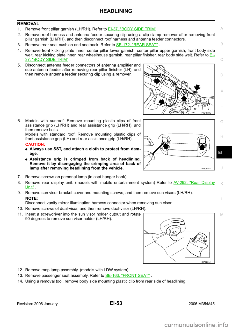
5. Disconnect antenna feeder connectors of antenna amplifier and
sub-antenna feeder after removing rear pillar finisher (LH), and
then remove antenna feeder securing clip using a remover.
6. Models with sunroof: Remove mounting plastic clips of front
assistance grip (LH/RH) and rear assistance grip (LH/RH), and
then remove bolts.
Models with standard roof: Remove mounting plastic clips of
front assistance grip (LH) and rear assistance grip (LH/RH).
CAUTION:
Always use SST, and attach a cloth to protect from dam-
age.
Assistance grip is crimped from back of headlining.
Remove it by disengaging the crimping area of back of
lamp after removing headlining from the vehicle.
7. Remove screws on personal lamp (in coat hanger hook).
8. Remove rear display unit. (models with mobile entertainment system) Refer to AV- 2 9 2 , "
Rear Display
Unit" .
9. Remove sun visor bracket cover and mounting screws, and then remove sun visors (LH/RH).
NOTE:
Disconnect vanity mirror illumination harness connector when removing sun visor.
10. Remove screws of dual-visor, and then remove dual-visor (LH/RH).
11. Insert a screwdriver into the sun visor holder cutout and rotate
90 degrees to remove sun visor holder (LH/RH).
12. Remove map lamp assembly. (models with LDW system)
13. Remove passenger seat assembly. Refer to SE-163, "
FRONT SEAT" .
14. Using a removal tool, remove body side mounting plastic clip from rear side of headlining.
PIIB4939E
PIIB3585J
SIIA0224J
Page 3059 of 5621

EI-54
HEADLINING
Revision: 2006 January2006 M35/M45
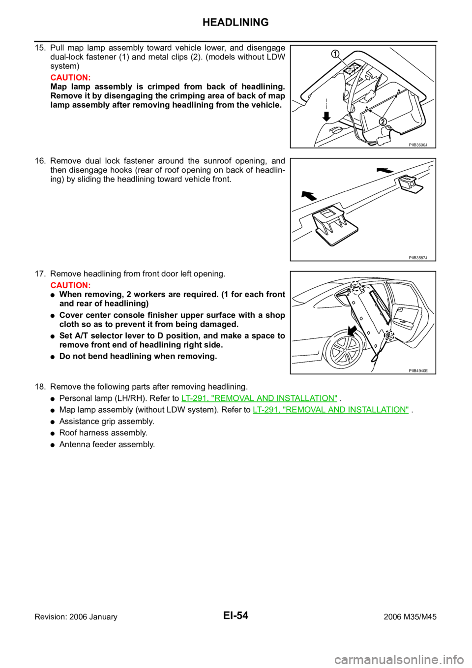
15. Pull map lamp assembly toward vehicle lower, and disengage
dual-lock fastener (1) and metal clips (2). (models without LDW
system)
CAUTION:
Map lamp assembly is crimped from back of headlining.
Remove it by disengaging the crimping area of back of map
lamp assembly after removing headlining from the vehicle.
16. Remove dual lock fastener around the sunroof opening, and
then disengage hooks (rear of roof opening on back of headlin-
ing) by sliding the headlining toward vehicle front.
17. Remove headlining from front door left opening.
CAUTION:
When removing, 2 workers are required. (1 for each front
and rear of headlining)
Cover center console finisher upper surface with a shop
cloth so as to prevent it from being damaged.
Set A/T selector lever to D position, and make a space to
remove front end of headlining right side.
Do not bend headlining when removing.
18. Remove the following parts after removing headlining.
Personal lamp (LH/RH). Refer to LT-291, "REMOVAL AND INSTALLATION" .
Map lamp assembly (without LDW system). Refer to LT- 2 9 1 , "REMOVAL AND INSTALLATION" .
Assistance grip assembly.
Roof harness assembly.
Antenna feeder assembly.
PIIB3600J
PIIB3587J
PIIB4940E