Page 4813 of 5621
MA-36
CHASSIS AND BODY MAINTENANCE
Revision: 2006 January2006 M35/M45
Checking Disc BrakeNLS0008C
ROTOR
Check condition, wear, and damage.
CALIPER
Check for leakage.
PA D
Check for wear or damage.
Checking Steering Gear and LinkageNLS0008D
STEERING GEAR
Check gear housing and boots for looseness, damage and
grease leakage.
Check connection with steering column for looseness.
STEERING LINKAGE
Check ball joint, dust cover and other component parts for looseness, wear, damage and grease leakage.
Front Rear
Brake modelCLZ31VD
CLZ31VBAD14VF
AD14VE
Standard thickness 28.0 mm (1.102 in) 16.0 mm (0.631 in)
Maximum runout 0.035 mm (0.0014 in) 0.055mm (0.0022 in)
Minimum thickness (Wear limit) 26.0 mm (1.024 in) 14.0 mm (0.551 in)
SMA922A
Brake modelCLZ31VD
CLZ31VBAD14VF
AD14VE
Standard thickness 11.0 mm (0.433 in) 8.5 mm (0.335 in)
Minimum thickness (Wear limit) 2.0 mm (0.079 in) 2.0 mm (0.079 in)
BRA0010D
SLIA0014E
Page 4814 of 5621

CHASSIS AND BODY MAINTENANCE
MA-37
C
D
E
F
G
H
I
J
K
MA
B
MA
Revision: 2006 January2006 M35/M45
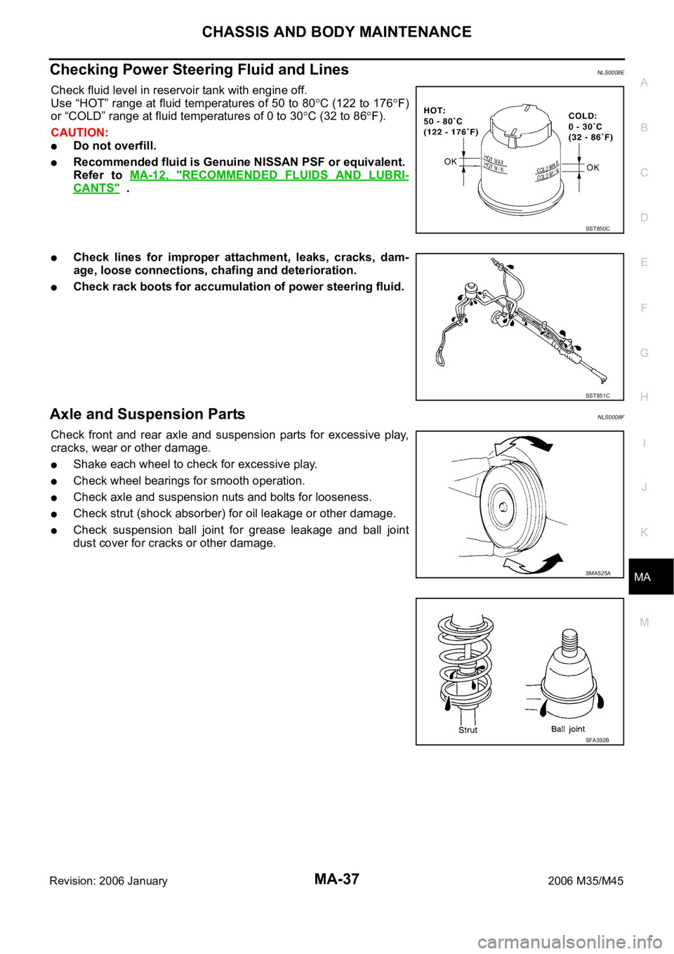
Checking Power Steering Fluid and LinesNLS0008E
Check fluid level in reservoir tank with engine off.
Use “HOT” range at fluid temperatures of 50 to 80
C (122 to 176F)
or “COLD” range at fluid temperatures of 0 to 30
C (32 to 86F).
CAUTION:
Do not overfill.
Recommended fluid is Genuine NISSAN PSF or equivalent.
Refer to MA-12, "
RECOMMENDED FLUIDS AND LUBRI-
CANTS" .
Check lines for improper attachment, leaks, cracks, dam-
age, loose connections, chafing and deterioration.
Check rack boots for accumulation of power steering fluid.
Axle and Suspension PartsNLS0008F
Check front and rear axle and suspension parts for excessive play,
cracks, wear or other damage.
Shake each wheel to check for excessive play.
Check wheel bearings for smooth operation.
Check axle and suspension nuts and bolts for looseness.
Check strut (shock absorber) for oil leakage or other damage.
Check suspension ball joint for grease leakage and ball joint
dust cover for cracks or other damage.
SST850C
SST851C
SMA525A
SFA392B
Page 4815 of 5621
MA-38
CHASSIS AND BODY MAINTENANCE
Revision: 2006 January2006 M35/M45
Drive ShaftNLS0008G
Check boot and drive shaft for cracks, wear, damage and grease
leakage.
Lubricating Locks, Hinges and Hood LatchNLS0008H
SFA108A
PIIB6450E
Page 4816 of 5621

CHASSIS AND BODY MAINTENANCE
MA-39
C
D
E
F
G
H
I
J
K
MA
B
MA
Revision: 2006 January2006 M35/M45
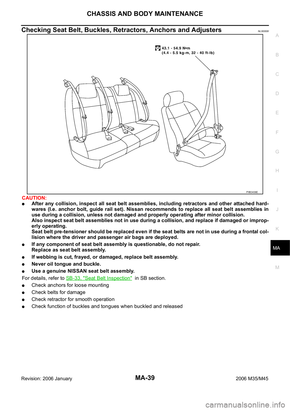
Checking Seat Belt, Buckles, Retractors, Anchors and AdjustersNLS0008I
CAUTION:
After any collision, inspect all seat belt assemblies, including retractors and other attached hard-
wares (I.e. anchor bolt, guide rail set). Nissan recommends to replace all seat belt assemblies in
use during a collision, unless not damaged and properly operating after minor collision.
Also inspect seat belt assemblies not in use during a collision, and replace if damaged or improp-
erly operating.
Seat belt pre-tensioner should be replaced even if the seat belts are not in use during a frontal col-
lision where the driver and passenger air bags are deployed.
If any component of seat belt assembly is questionable, do not repair.
Replace as seat belt assembly.
If webbing is cut, frayed, or damaged, replace belt assembly.
Never oil tongue and buckle.
Use a genuine NISSAN seat belt assembly.
For details, refer to SB-33, "
Seat Belt Inspection" in SB section.
Check anchors for loose mounting
Check belts for damage
Check retractor for smooth operation
Check function of buckles and tongues when buckled and released
PIIB3436E
Page 4828 of 5621

PG-1
POWER SUPPLY, GROUND & CIRCUIT ELEMENTS
K ELECTRICAL
CONTENTS
C
D
E
F
G
H
I
J
L
M
SECTION PG
A
B
PG
Revision: 2006 January2006 M35/M45
POWER SUPPLY, GROUND & CIRCUIT ELEMENTS
POWER SUPPLY ROUTING CIRCUIT ...................... 3
Schematic ................................................................ 3
Wiring Diagram — POWER — ................................. 5
BATTERY POWER SUPPLY — IGNITION SW.
IN ANY POSITION ................................................ 5
ACCESSORY POWER SUPPLY — IGNITION
SW. IN “ACC” OR “ON” ........................................ 11
IGNITION POWER SUPPLY — IGNITION SW.
IN “ON” AND/OR “START” .................................. 12
Fuse ....................................................................... 17
Fusible Link ............................................................ 17
Circuit Breaker ....................................................... 17
IPDM E/R (INTELLIGENT POWER DISTRIBUTION
MODULE ENGINE ROOM) ...................................... 18
System Description ................................................ 18
SYSTEMS CONTROLLED BY IPDM E/R ........... 18
CAN COMMUNICATION LINE CONTROL ......... 18
IPDM E/R STATUS CONTROL ........................... 19
CAN Communication System Description .............. 19
CAN Communication Unit ...................................... 19
Function of Detecting Ignition Relay Malfunction ... 19
CONSULT-II Function (IPDM E/R) ......................... 20
CONSULT-II BASIC OPERATION ....................... 20
SELF-DIAG RESULTS ........................................ 21
DATA MONITOR ................................................. 22
CAN DIAG SUPPORT MNTR ............................. 23
ACTIVE TEST ..................................................... 23
Auto Active Test ..................................................... 24
DESCRIPTION .................................................... 24
OPERATION PROCEDURE ............................... 24
INSPECTION IN AUTO ACTIVE TEST MODE ... 25
Schematic .............................................................. 28
IPDM E/R Terminal Arrangement ........................... 29
Check IPDM E/R Power Supply and Ground Circuit ... 30
Inspection with CONSULT-II (Self-Diagnosis) ........ 31
Removal and Installation of IPDM E/R ................... 31
REMOVAL ........................................................
... 31
INSTALLATION ................................................... 32
PDU (POWER DISTRIBUTION UNIT) ...................... 33
Component Parts and Harness Connector Location ... 33System Description ................................................. 33
PUSH-BUTTON IGNITION SWITCH OPERAT-
ING PROCEDURE .............................................. 33
Wiring Diagram — PDU — ..................................... 35
Terminals and Reference Value for Intelligent Key
Unit ......................................................................... 37
Terminals and Reference Value for PDU ................ 38
Work Flow ............................................................... 38
Trouble Diagnosis Symptom Chart ......................... 39
Check CAN Communication System ...................... 39
Check PDU Power Supply and Ground Circuit ...... 40
Check Push-Button Ignition Switch (Ignition Switch)
System .................................................................... 40
Check Push-Button Ignition Switch (Indicator Cir-
cuit) System ............................................................ 42
PDU Communication Circuit System 1 ................... 43
PDU Communication Circuit System 2 ................... 44
Removal and Installation of PDU ............................ 45
REMOVAL ........................................................
... 45
INSTALLATION ................................................... 45
GROUND ................................................................... 46
Ground Distribution ................................................. 46
MAIN HARNESS ................................................. 46
ENGINE ROOM HARNESS ................................ 51
ENGINE CONTROL HARNESS/VQ ENGINE
MODELS ............................................................. 55
ENGINE CONTROL HARNESS/VK ENGINE
MODELS ............................................................. 56
BODY HARNESS ................................................ 57
BODY NO. 2 HARNESS ..................................... 62
HARNESS ................................................................. 63
Harness Layout ...................................................... 63
HOW TO READ HARNESS LAYOUT ................. 63
OUTLINE ............................................................. 64
MAIN HARNESS ................................................. 65
NAVIGATION SUB-HARNESS & A/C HARNESS ... 70
ENGINE ROOM HARNESS ................................ 71
ENGINE CONTROL HARNESS (VQ ENGINE) ... 78
ENGINE CONTROL HARNESS (VK ENGINE) ... 81
BODY HARNESS ................................................ 84
Page 4829 of 5621

PG-2Revision: 2006 January2006 M35/M45 BODY NO. 2 HARNESS ...................................... 88
TAIL HARNESS ................................................... 89
ROOM LAMP HARNESS .................................... 90
FRONT DOOR HARNESS .................................. 91
REAR DOOR HARNESS .................................... 92
Wiring Diagram Codes (Cell Codes) ....................... 93
ELECTRICAL UNITS LOCATION ............................. 96
Electrical Units Location ......................................
... 96
ENGINE COMPARTMENT .................................. 96
PASSENGER COMPARTMENT .......................... 98
LUGGAGE COMPARTMENT ............................101
HARNESS CONNECTOR .......................................102
Description ............................................................102
HARNESS CONNECTOR (TAB-LOCKING
TYPE) ................................................................102
HARNESS CONNECTOR (SLIDE-LOCKING TYPE) ................................................................103
ELECTRICAL UNITS ..............................................104
Terminal Arrangement ...........................................104
SMJ (SUPER MULTIPLE JUNCTION) ....................106
Terminal Arrangement ...........................................106
STANDARDIZED RELAY ........................................109
Description ............................................................109
NORMAL OPEN, NORMAL CLOSED AND
MIXED TYPE RELAYS ......................................109
TYPE OF STANDARDIZED RELAYS ................109
FUSE BLOCK - JUNCTION BOX (J/B) .................. 111
Terminal Arrangement ........................................... 111
FUSE, FUSIBLE LINK AND RELAY BOX ..............112
Terminal Arrangement ...........................................112
Page 4884 of 5621
GROUND
PG-57
C
D
E
F
G
H
I
J
L
MA
B
PG
Revision: 2006 January2006 M35/M45
BODY HARNESS
CKIT0677E
Page 4889 of 5621
PG-62
GROUND
Revision: 2006 January2006 M35/M45
BODY NO. 2 HARNESS
CKIT0682E