2006 INFINITI M35 Body
[x] Cancel search: BodyPage 4638 of 5621

TURN SIGNAL AND HAZARD WARNING LAMPS
LT-211
C
D
E
F
G
H
I
J
L
MA
B
LT
Revision: 2006 January2006 M35/M45
TURN SIGNAL AND HAZARD WARNING LAMPSPFP:26120
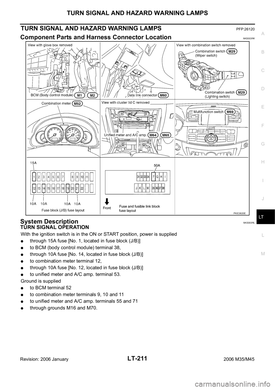
Component Parts and Harness Connector LocationNKS003RK
System DescriptionNKS003RL
TURN SIGNAL OPERATION
With the ignition switch is in the ON or START position, power is supplied
through 15A fuse [No. 1, located in fuse block (J/B)]
to BCM (body control module) terminal 38,
through 10A fuse [No. 14, located in fuse block (J/B)]
to combination meter terminal 12,
through 10A fuse [No. 12, located in fuse block (J/B)]
to unified meter and A/C amp. terminal 53.
Ground is supplied
to BCM terminal 52
to combination meter terminals 9, 10 and 11
to unified meter and A/C amp. terminals 55 and 71
through grounds M16 and M70.
PKIC0620E
Page 4676 of 5621

PARKING, LICENSE PLATE AND TAIL LAMPS
LT-249
C
D
E
F
G
H
I
J
L
MA
B
LT
Revision: 2006 January2006 M35/M45
PARKING, LICENSE PLATE AND TAIL LAMPSPFP:26550
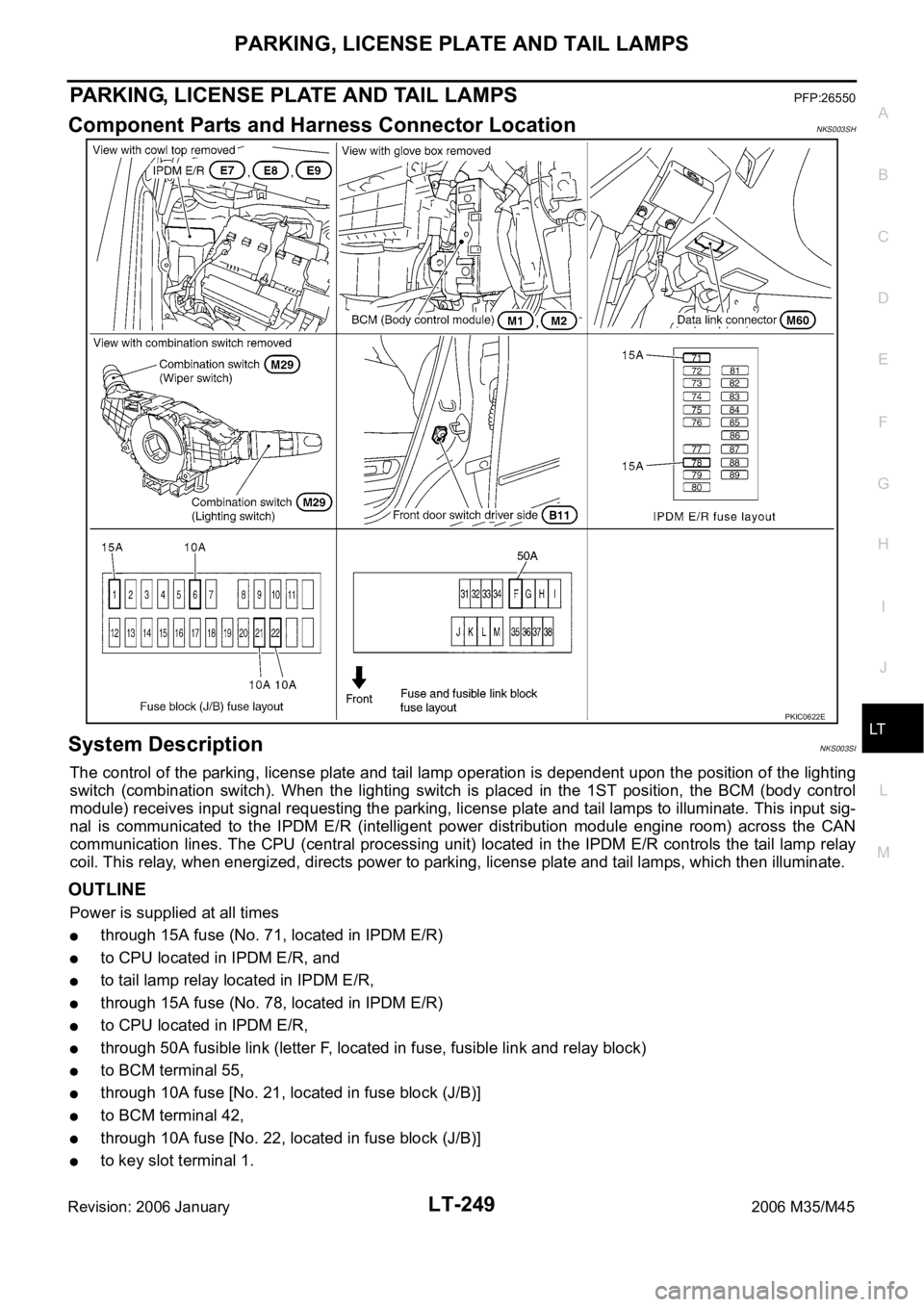
Component Parts and Harness Connector LocationNKS003SH
System DescriptionNKS003SI
The control of the parking, license plate and tail lamp operation is dependent upon the position of the lighting
switch (combination switch). When the lighting switch is placed in the 1ST position, the BCM (body control
module) receives input signal requesting the parking, license plate and tail lamps to illuminate. This input sig-
nal is communicated to the IPDM E/R (intelligent power distribution module engine room) across the CAN
communication lines. The CPU (central processing unit) located in the IPDM E/R controls the tail lamp relay
coil. This relay, when energized, directs power to parking, license plate and tail lamps, which then illuminate.
OUTLINE
Power is supplied at all times
through 15A fuse (No. 71, located in IPDM E/R)
to CPU located in IPDM E/R, and
to tail lamp relay located in IPDM E/R,
through 15A fuse (No. 78, located in IPDM E/R)
to CPU located in IPDM E/R,
through 50A fusible link (letter F, located in fuse, fusible link and relay block)
to BCM terminal 55,
through 10A fuse [No. 21, located in fuse block (J/B)]
to BCM terminal 42,
through 10A fuse [No. 22, located in fuse block (J/B)]
to key slot terminal 1.
PKIC0622E
Page 4694 of 5621

INTERIOR ROOM LAMP
LT-267
C
D
E
F
G
H
I
J
L
MA
B
LT
Revision: 2006 January2006 M35/M45
INTERIOR ROOM LAMPPFP:26410
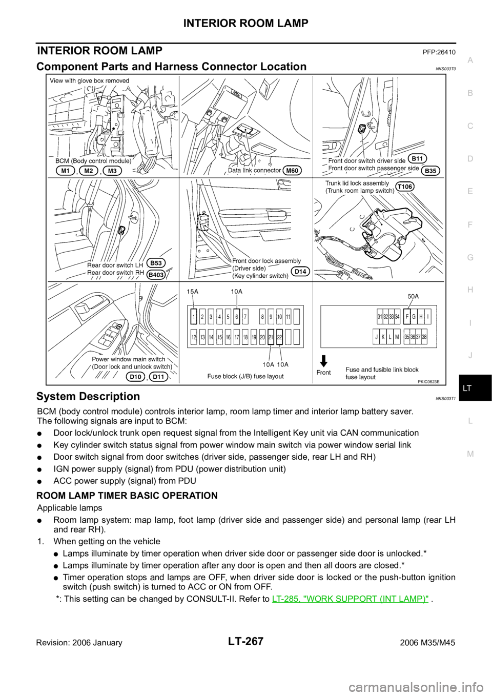
Component Parts and Harness Connector LocationNKS003T0
System DescriptionNKS003T1
BCM (body control module) controls interior lamp, room lamp timer and interior lamp battery saver.
The following signals are input to BCM:
Door lock/unlock trunk open request signal from the Intelligent Key unit via CAN communication
Key cylinder switch status signal from power window main switch via power window serial link
Door switch signal from door switches (driver side, passenger side, rear LH and RH)
IGN power supply (signal) from PDU (power distribution unit)
ACC power supply (signal) from PDU
ROOM LAMP TIMER BASIC OPERATION
Applicable lamps
Room lamp system: map lamp, foot lamp (driver side and passenger side) and personal lamp (rear LH
and rear RH).
1. When getting on the vehicle
Lamps illuminate by timer operation when driver side door or passenger side door is unlocked.*
Lamps illuminate by timer operation after any door is open and then all doors are closed.*
Timer operation stops and lamps are OFF, when driver side door is locked or the push-button ignition
switch (push switch) is turned to ACC or ON from OFF.
*: This setting can be changed by CONSULT-II. Refer to LT- 2 8 5 , "
WORK SUPPORT (INT LAMP)" .
PKIC0623E
Page 4695 of 5621

LT-268
INTERIOR ROOM LAMP
Revision: 2006 January2006 M35/M45
2. When getting off the vehicle
Lamps illuminate by timer operation when the push-button ignition switch (push switch) is turned OFF.*
Lamps illuminate by timer operation after any door is open and then all doors are closed.*
Timer operation stops and lamps are OFF, when driver side door is locked.
*: This setting can be changed by CONSULT-II. Refer to LT- 2 8 5 , "
WORK SUPPORT (INT LAMP)" .
POWER SUPPLY AND GROUND
Power is supplied at all times
through 50A fusible link (letter F, located in fuse and fusible link block)
to BCM terminal 55,
through 10A fuse [No. 21, located in fuse block (J/B)]
to BCM (body control module) terminal 42,
through 10A fuse [No. 22, located in fuse block (J/B)]
to key slot terminal 1.
With the ignition switch in the ON or START position, power is supplied
through 15A fuse [No. 1, located in fuse block (J/B)]
to BCM terminal 38.
With the ignition switch in the ACC or ON position, power is supplied
through 10A fuse [No. 6, located in fuse block (J/B)]
to BCM terminal 11.
Ground is supplied
to BCM terminal 52
through grounds M16 and M70.
When the driver side door is opened, ground is supplied
to BCM terminal 62
through front door switch driver side terminal 2
through case ground of front door switch driver side.
When the passenger side door is opened, ground is supplied
to BCM terminal 12
through front door switch passenger side terminal 2
through case ground of front door switch passenger side.
When the rear door LH is opened, ground is supplied
to BCM terminal 63
through rear door switch LH terminal 2
through case ground of rear door switch LH.
When the rear door RH is opened, ground is supplied
to BCM terminal 13
through rear door switch RH terminal 2
through case ground of rear door switch RH.
When driver side door is unlocked by door lock and unlock switch, BCM receives a ground signal
to BCM terminal 22
through power window main switch (door lock and unlock switch) terminal 14 or power window sub-switch
(front passenger side) (door lock and unlock switch) terminal 16
through power window main switch (door lock and unlock switch) terminal 17 or power window sub-switch
(front passenger side) (door lock and unlock switch) terminal 11
through grounds M16 and M70.
When the driver side door is unlocked by the front door lock assembly (driver side) (key cylinder switch), BCM
receives a ground signal
to BCM terminal 22
through power window main switch (door lock and unlock switch) terminals 14 and 6
Page 4722 of 5621

ILLUMINATION
LT-295
C
D
E
F
G
H
I
J
L
MA
B
LT
Revision: 2006 January2006 M35/M45
ILLUMINATIONPFP:27545
System DescriptionNKS003TH
Control of the illumination lamps operation is dependent upon the position of the lighting switch (combination
switch). When the lighting switch is placed in the 1ST or 2ND position (or if the auto light system is activated)
the BCM (body control module) receives input signal requesting the illumination lamps to illuminate. This input
signal is communicated to the IPDM E/R (intelligent power distribution module engine room) across the CAN
communication lines. The CPU (central processing unit) located in the IPDM E/R controls the tail lamp relay
coil. This relay, when energized, directs power to the illumination lamps, which then illuminate.
OUTLINE
Power is supplied at all times
through 15A fuse (No. 71, located in IPDM E/R)
to tail lamp relay, located in IPDM E/R, and
to CPU located in IPDM E/R,
through 15A fuse (No. 78, located in IPDM E/R)
to CPU located in IPDM E/R,
through 50A fusible link (letter F, located in fuse, fusible link and relay block)
to BCM terminal 55,
through 10A fuse [No. 21, located in fuse block (J/B)]
to BCM terminal 42 and
to combination meter terminal 23,
through 10A fuse [No. 19, located in fuse block (J/B)]
to unified meter and A/C amp. terminal 54,
through 10A fuse [No. 22, located in fuse block (J/B)]
to intelligent key unit terminals 1, 41 and 57.
With the ignition switch in the ON or START position, power is supplied
through 15A fuse [No. 1, located in fuse block (J/B)]
to BCM terminal 38,
through 10A fuse [No. 14, located in fuse block (J/B)]
to combination meter terminal 12,
through 10A fuse [No. 12, located in fuse block (J/B)]
to unified meter and A/C amp. terminal 53 and
to rear sunshade cancel relay terminal 1.
With the ignition switch in the ACC or ON position, power is supplied
through 10A fuse [No. 6, located in fuse block (J/B)]
to BCM terminal 11
to unified meter and A/C amp. terminal 41 and
to combination meter terminal 2.
Ground is supplied
to BCM terminal 52
to unified meter and A/C amp. terminals 55 and 71
to combination meter terminals 9, 10, and 11
to Intelligent Key unit terminals 20, 40, 56 and 72, and
to illumination control switch terminal 3
through grounds M16 and M70,
to IPDM E/R terminals 38 and 51
through grounds E22 and E43.
Page 4761 of 5621
![INFINITI M35 2006 Factory Service Manual LU-18
[VQ35DE]
OIL PUMP
Revision: 2006 January2006 M35/M45
OIL PUMPPFP:15010
ComponentsNBS004Q3
Removal and InstallationNBS004Q4
REMOVAL
1. Remove oil pans (lower and upper) and oil strainer. Refer to INFINITI M35 2006 Factory Service Manual LU-18
[VQ35DE]
OIL PUMP
Revision: 2006 January2006 M35/M45
OIL PUMPPFP:15010
ComponentsNBS004Q3
Removal and InstallationNBS004Q4
REMOVAL
1. Remove oil pans (lower and upper) and oil strainer. Refer to](/manual-img/42/57023/w960_57023-4760.png)
LU-18
[VQ35DE]
OIL PUMP
Revision: 2006 January2006 M35/M45
OIL PUMPPFP:15010
ComponentsNBS004Q3
Removal and InstallationNBS004Q4
REMOVAL
1. Remove oil pans (lower and upper) and oil strainer. Refer to EM-29, "OIL PAN AND OIL STRAINER" .
2. Remove front timing chain case and timing chain (primary). Refer to EM-64, "
TIMING CHAIN" .
3. Remove oil pump assembly.
INSTALLATION
CAUTION:
Before installation, apply new engine oil to the parts as instructed in the figure.
Note the following, and install in the reverse order of removal.
When installing, align crankshaft flat faces with oil pump inner rotor flat faces.
INSPECTION AFTER INSTALLATION
1. Check the engine oil level. Refer to LU-7, "ENGINE OIL" .
2. Start the engine, and check there is no leaks of engine oil.
3. Stop the engine and wait for 10 minutes.
4. Check the engine oil level and adjust the level. Refer to LU-7, "
ENGINE OIL" .
Disassembly and AssemblyNBS004Q5
DISASSEMBLY
1. Remove oil pump cover.
2. Remove oil pump inner rotor and oil pump outer rotor from oil pump body.
3. After removing regulator valve plug, remove regulator valve spring and regulator valve.
1. Oil pump body 2. Oil pump outer rotor 3. Oil pump inner rotor
4. Oil pump cover 5. Regulator valve plug 6. Regulator valve spring
7. Regulator valve
SBIA0481E
Page 4762 of 5621
![INFINITI M35 2006 Factory Service Manual OIL PUMP
LU-19
[VQ35DE]
C
D
E
F
G
H
I
J
K
L
MA
LU
Revision: 2006 January2006 M35/M45
INSPECTION AFTER DISASSEMBLY
Oil Pump Clearance
Measure the clearance with feeler gauge.
–Clearance between oil INFINITI M35 2006 Factory Service Manual OIL PUMP
LU-19
[VQ35DE]
C
D
E
F
G
H
I
J
K
L
MA
LU
Revision: 2006 January2006 M35/M45
INSPECTION AFTER DISASSEMBLY
Oil Pump Clearance
Measure the clearance with feeler gauge.
–Clearance between oil](/manual-img/42/57023/w960_57023-4761.png)
OIL PUMP
LU-19
[VQ35DE]
C
D
E
F
G
H
I
J
K
L
MA
LU
Revision: 2006 January2006 M35/M45
INSPECTION AFTER DISASSEMBLY
Oil Pump Clearance
Measure the clearance with feeler gauge.
–Clearance between oil pump outer rotor and oil pump body
(position “1”)
–Tip clearance between oil pump inner rotor and oil pump outer
rotor (position “2”)
–If out of the standard, replace inner rotor and outor rotor.
Measure the clearance with feeler gauge and straightedge.
–Side clearance between oil pump inner rotor and oil pump body
(position “3”)
–Side clearance between oil pump outer rotor and oil pump body
(position “4”)
Calculate the clearance between oil pump inner rotor and oil pump body as follows:
OIL PUMP BODY INNER DIAMETER
–Measure the inner diameter of oil pump body with inside
micrometer. (Position “5”)
OIL PUMP INNER ROTOR OUTER DIAMETER
–Measure the outer diameter of protruded portion of oil pump
inner rotor with micrometer. (Position “6”)
OIL PUMP INNER ROTOR TO OIL PUMP BODY CLEARANCE
–(Clearance) = (Oil pump body inner diameter) – (Oil pump inner rotor outer diameter)
If measured/calculated values are out of the standard, replace oil pump assembly. Standard : 0.114 - 0.260 mm (0.0045 - 0.0102 in)
Standard : Below 0.180 mm (0.0071 in)
SLC932A
Standard : 0.030 - 0.070 mm (0.0012 - 0.0028 in)
Standard : 0.050 - 0.110 mm (0.0020 - 0.0043 in)
SLC933A
PBIC0821E
Standard : 0.045 - 0.091 mm (0.0018 - 0.0036 in)
Page 4764 of 5621
![INFINITI M35 2006 Factory Service Manual SERVICE DATA AND SPECIFICATIONS (SDS)
LU-21
[VQ35DE]
C
D
E
F
G
H
I
J
K
L
MA
LU
Revision: 2006 January2006 M35/M45
SERVICE DATA AND SPECIFICATIONS (SDS)PFP:00030
Standard and LimitNBS004Q6
ENGINE OIL P INFINITI M35 2006 Factory Service Manual SERVICE DATA AND SPECIFICATIONS (SDS)
LU-21
[VQ35DE]
C
D
E
F
G
H
I
J
K
L
MA
LU
Revision: 2006 January2006 M35/M45
SERVICE DATA AND SPECIFICATIONS (SDS)PFP:00030
Standard and LimitNBS004Q6
ENGINE OIL P](/manual-img/42/57023/w960_57023-4763.png)
SERVICE DATA AND SPECIFICATIONS (SDS)
LU-21
[VQ35DE]
C
D
E
F
G
H
I
J
K
L
MA
LU
Revision: 2006 January2006 M35/M45
SERVICE DATA AND SPECIFICATIONS (SDS)PFP:00030
Standard and LimitNBS004Q6
ENGINE OIL PRESSURE
*: Engine oil temperature at 80C (176F)
ENGINE OIL CAPACITY (APPROXIMATE)
Unit: (US qt, lmp qt)
OIL PUMP
Unit: mm (in)
REGULATOR VALVE
Unit: mm (in) Engine speed (rpm)
Approximate discharge pressure* [kPa (kg/cm
2 , psi)]
Idle speed More than 98 (1.0, 14)
2,000 More than 294 (3.0, 43)
Drain and refill With oil filter change 4.7 (5, 4-1/8)
Without oil filter change 4.4 (4-5/8, 3-7/8)
Dry engine (Overhaul)5.4 (5-3/4, 4-3/4)
Oil pump body to oil pump outer rotor radial clearance 0.114 - 0.260 (0.0045 - 0.0102)
Oil pump inner rotor to oil pump outer rotor tip clearance Below 0.180 (0.0071)
Oil pump body to oil pump inner rotor axial clearance 0.030 - 0.070 (0.0012 - 0.0028)
Oil pump body to oil pump outer rotor axial clearance 0.050 - 0.110 (0.0020 - 0.0043)
Oil pump inner rotor to brazed portion of housing clearance 0.045 - 0.091 (0.0018 - 0.0036)
Regulator valve to oil pump cover clearance 0.040 - 0.097 (0.0016 - 0.0038)