2006 INFINITI M35 Body
[x] Cancel search: BodyPage 3616 of 5621
![INFINITI M35 2006 Factory Service Manual REVERSE INTERLOCK DOOR MIRROR SYSTEM
GW-97
C
D
E
F
G
H
J
K
L
MA
B
GW
Revision: 2006 January2006 M35/M45
through 10A fuse [No.21, located in the fuse block (J/B)]
to automatic drive positioner control INFINITI M35 2006 Factory Service Manual REVERSE INTERLOCK DOOR MIRROR SYSTEM
GW-97
C
D
E
F
G
H
J
K
L
MA
B
GW
Revision: 2006 January2006 M35/M45
through 10A fuse [No.21, located in the fuse block (J/B)]
to automatic drive positioner control](/manual-img/42/57023/w960_57023-3615.png)
REVERSE INTERLOCK DOOR MIRROR SYSTEM
GW-97
C
D
E
F
G
H
J
K
L
MA
B
GW
Revision: 2006 January2006 M35/M45
through 10A fuse [No.21, located in the fuse block (J/B)]
to automatic drive positioner control unit terminal 34 and
to driver seat control unit terminal 40.
Ground is supplied
to automatic drive positioner control unit terminals 40 and 48.
through body grounds M16 and M70.
to driver seat control unit terminals 32 and 48.
through body grounds B5, B40 and B131.
to door mirror remote control switch terminal 13
through body grounds M16 and M70.
REVERSE INTERLOCK DOOR MIRROR SYSTEM OPERATION
When the ignition switch is in ON position, A/T control device into R position. Then TCM (in A/T assembly)
detects it and sends the A/T shift position signal to the driver seat control unit via DATA LINE (CAN H,
CAN L).
When selecting either left and right changeover switch, the automatic drive position control unit judges
which door mirror is selected according to the voltage of terminals 2 and 18. And then, it sends the signal
to driver seat control unit via communication signal.
When the driver seat control unit receives the A/T shift position signal and changeover switch signal, it
sends the operation signal to the automatic drive positioner control unit using the communication signal so
that the each mirror sensor voltage stays in a specified value.
Door mirror (RH) selected
Supply the power from terminals 14, 15 and 30 to door mirror (RH) terminals 5, 6 and 7 so that the voltage
of terminals 5 and 21 stays in a specified value. Then, adjust the mirror angle.
Door mirror (LH) selected
Supply the power from terminals 16, 31 and 32 to door mirror (LH) terminals 5, 6 and 7 do that the voltage
of terminals 6 and 22 is the specified value. Then, adjust the mirror angle.
CAN Communication System DescriptionNIS00232
CAN (Controller Area Network) is a serial communication line for real time application. It is an on-vehicle mul-
tiplex communication line with high data communication speed and excellent error detection ability. Many elec-
tronic control units are equipped onto a vehicle, and each control unit shares information and links with other
control units during operation (not independent). In CAN communication, control units are connected with 2
communication lines (CAN H line, CAN L line) allowing a high rate of information transmission with less wiring.
Each control unit transmits/receives data but selectively reads required data only.
CAN Communication UnitNIS00233
Refer to LAN-34, "CAN Communication Unit" .
Page 3640 of 5621
DOOR MIRROR
GW-121
C
D
E
F
G
H
J
K
L
MA
B
GW
Revision: 2006 January2006 M35/M45
Disassembly and AssemblyNIS0023I
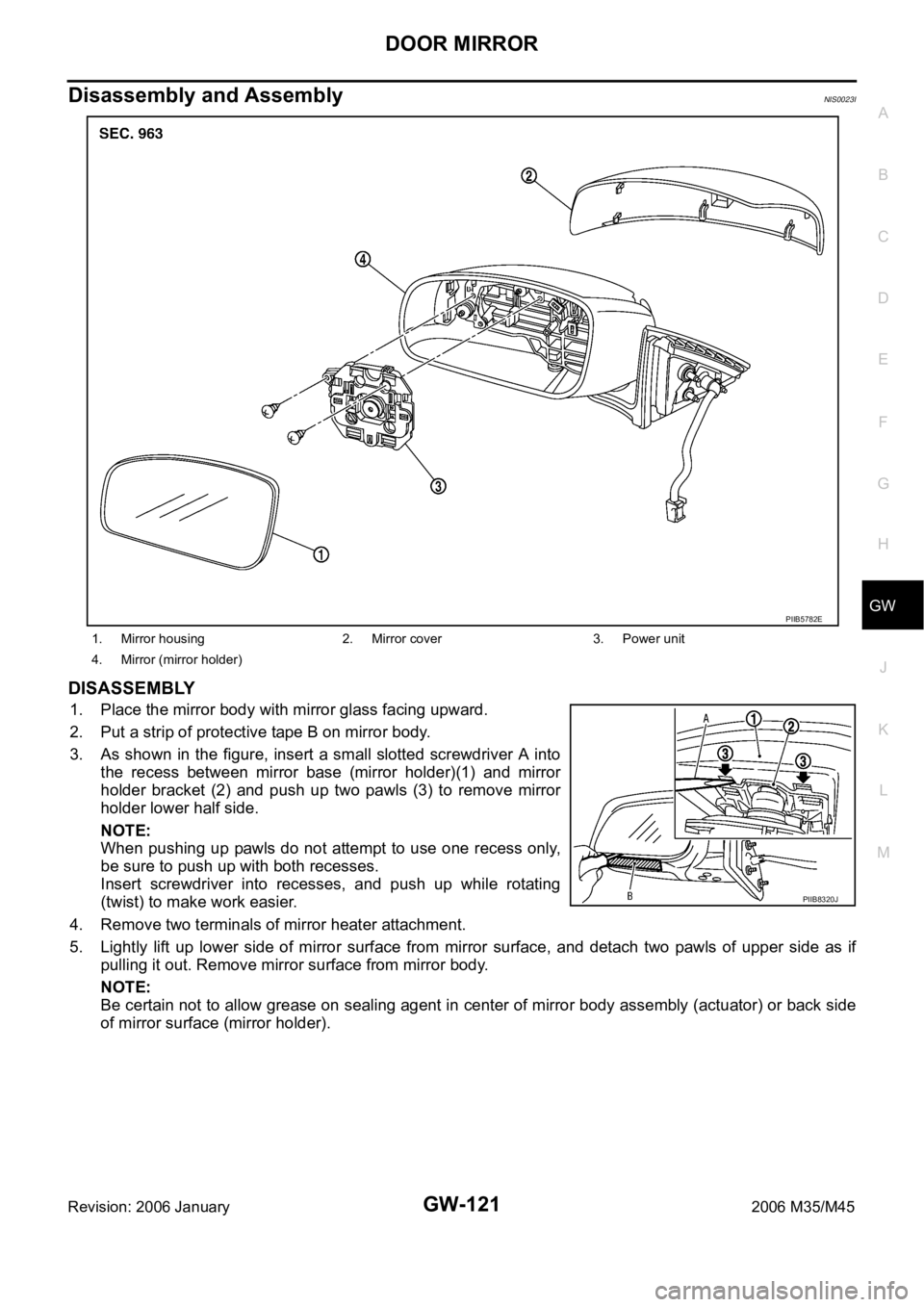
DISASSEMBLY
1. Place the mirror body with mirror glass facing upward.
2. Put a strip of protective tape B on mirror body.
3. As shown in the figure, insert a small slotted screwdriver A into
the recess between mirror base (mirror holder)(1) and mirror
holder bracket (2) and push up two pawls (3) to remove mirror
holder lower half side.
NOTE:
When pushing up pawls do not attempt to use one recess only,
be sure to push up with both recesses.
Insert screwdriver into recesses, and push up while rotating
(twist) to make work easier.
4. Remove two terminals of mirror heater attachment.
5. Lightly lift up lower side of mirror surface from mirror surface, and detach two pawls of upper side as if
pulling it out. Remove mirror surface from mirror body.
NOTE:
Be certain not to allow grease on sealing agent in center of mirror body assembly (actuator) or back side
of mirror surface (mirror holder).
1. Mirror housing 2. Mirror cover 3. Power unit
4. Mirror (mirror holder)
PIIB5782E
PIIB8320J
Page 3641 of 5621
GW-122
DOOR MIRROR
Revision: 2006 January2006 M35/M45
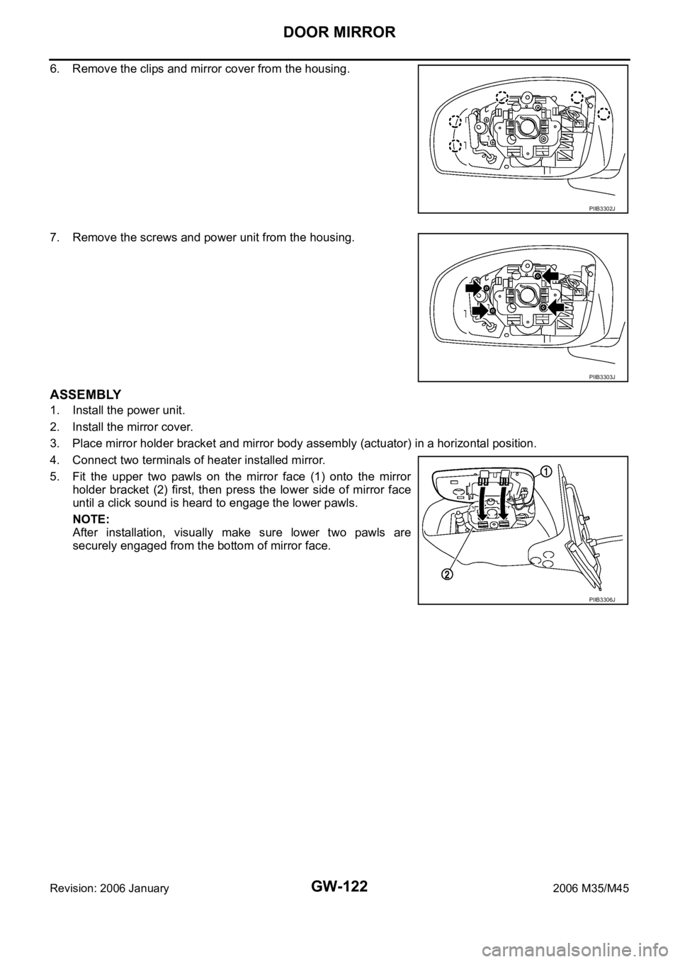
6. Remove the clips and mirror cover from the housing.
7. Remove the screws and power unit from the housing.
ASSEMBLY
1. Install the power unit.
2. Install the mirror cover.
3. Place mirror holder bracket and mirror body assembly (actuator) in a horizontal position.
4. Connect two terminals of heater installed mirror.
5. Fit the upper two pawls on the mirror face (1) onto the mirror
holder bracket (2) first, then press the lower side of mirror face
until a click sound is heard to engage the lower pawls.
NOTE:
After installation, visually make sure lower two pawls are
securely engaged from the bottom of mirror face.
PIIB3302J
PIIB3303J
PIIB3306J
Page 3643 of 5621
IDX-2
ALPHABETICAL INDEX
A
A/C air flow ...................................................... ATC-37
A/C component layout ..................................... ATC-25
A/C compressor mounting ........... ATC-155, ATC-158,
ATC-159
, ATC-160, ATC-162, ATC-164, ATC-165,
ATC-167
, ATC-168, ATC-169
A/C compressor precaution ............................. ATC-12
A/C compressor special service tool ................ ATC-16
A/C control operation (auto A/C) ...................... ATC-33
A/C diagnostic work flow (auto A/C) .............. ATC-111
A/C evaporator ............................................... ATC-168
A/C HFC134a (R134a) system precaution ........ ATC-6
A/C HFC134a (R134a) system service procedure .......
ATC-151
A/C HFC134a (R134a) system service tools ... ATC-17
A/C HFC134a system service equipment precaution ...
ATC-13
A/C lubricant (R134a) ...................................... ATC-26
A/C lubrication oil ........................................... ATC-174
A/C operational check ...................................... ATC-64
A/C self-diagnoses (auto A/C) ........ ATC-55, ATC-111
A/C service data specification ........................ ATC-174
A/C system description (auto A/C) ................... ATC-29
A/C trouble diagnoses (auto A/C) .................... ATC-40
A/C, A - Wiring diagram ................................... ATC-46
A/T fluid checking ...................... AT-13, AT-53, MA-29
A/T fluid cooler cleaning .................................... AT-14
A/T fluid replacement ............................. AT-12, MA-31
A/T fluid temperature sensor ........................... AT-135
A/T IND - Wiring diagram .................................... DI-57
A/T self-diagnoses ............................... AT-92, AT-103
A/T shift lock system ........................................ AT-229
A/T shift lock system - Wiring diagram ............ AT-230
A/T trouble diagnoses ........................................ AT-44
Accelerator control system ............................... ACC-3
Accelerator pedal position (APP) sensor ........ EC-626,
EC-633
, EC-647, EC-1358, EC-1365, EC-1379
Accelerator pedal released position learning .... EC-95,
EC-806
AF1B1-Wiring diagram ...... EC-249, EC-258, EC-267,
EC-277
, EC-657, EC-972, EC-981, EC-990, EC-1000,
EC-1389
AF1B2-Wiring diagram ...... EC-251, EC-260, EC-269,
EC-279
, EC-659, EC-974, EC-983, EC-992, EC-1002,
EC-1391
AF1HB1-Wiring diagram .................... EC-183, EC-905
AF1HB2-Wiring diagram .................... EC-185, EC-907
Air bag .............................................................. SRS-3
Air bag precautions ........................................... SRS-3
Air cleaner and air duct(VK45DE) ................... EM-177
Air cleaner and air duct(VQ35DE) .................... EM-17
Air cleaner filter replacement ............................ MA-25
Air cleaner filter replacement(VQ35DE) ........... MA-18
Air cleaner filter(VQ35DE) ................................ EM-18
Air conditioner cut control .................... EC-35, EC-745
Air flow meter - See Mass air flow sensor ...... EC-205,
EC-214
, EC-927, EC-936
Air fuel ratio sensor 1 ......... EC-246, EC-256, EC-265, EC-274
, EC-655, EC-969, EC-979, EC-988, EC-997,
EC-1387
Air fuel ratio sensor 1 heater ............. EC-182, EC-904
Air mix. door motor ......................... ATC-83, ATC-141
Alternator ........................................................... SC-23
Ambient sensor ............................. ATC-113, ATC-126
Angular tightening application ............................. EM-6
Angular tightening application(VK45DE) ........ EM-164
APPS1 - Wiring diagram ................. EC-628, EC-1360
APPS2 - Wiring diagram ................. EC-635, EC-1367
APPS3 - Wiring diagram ................. EC-649, EC-1381
ASC/BS - Wiring diagram ............... EC-587, EC-1313
ASC/SW - Wiring diagram .............. EC-570, EC-1296
ASCBOF - Wiring diagram .............. EC-708, EC-1450
ASCD .................................................. EC-36, EC-746
ASCD (automatic speed control device) ........... ACS-3
ASCIND - Wiring diagram ............... EC-715, EC-1457
AT indicator lamp ................................................ DI-56
Auto air conditioner - Wiring diagram ............. ATC-46
Auto amp ...................................................... ATC-125
Auto anti-dazzling inside mirror .......... GW-71, GW-72
Automatic amplifier ........... ATC-53, ATC-66, ATC-125
Automatic transmission fluid replacement ........ MA-32
AWD - Wiring diagram ....................................... TF-17
Axle ................................................................... MA-37
B
Back-up lamp ................................................... LT-246
Basic inspection .................................. EC-77, EC-788
Battery ................................................................. SC-4
Battery current sensor ....... EC-537, EC-543, EC-549,
EC-555
, EC-1263, EC-1269, EC-1275, EC-1281
Battery/Starting/Charging System Tester .......... SC-28
Battery/Starting/Charging System Tester(Battery) SC-7
Battery/Starting/Charging System Tester(Starting
system) .............................................................. SC-13
BCM (Body control module) .............................. BCS-3
Block heater(VK45DE) .................................... EM-249
Block heater(VQ35DE) ................................... EM-123
Blower motor ................................... ATC-89, ATC-132
Blower unit .................................................... ATC-130
Brake fluid level ................................................ MA-35
Brake hydraulic line ........................................... BR-12
Brake inspection ............................................... MA-36
Brake lines and cables inspection .................... MA-35
Brake pedal .......................................................... BR-6
Brake switch ................................... EC-598, EC-1329
BRK/SW - Wiring diagram .............. EC-600, EC-1331
Bulb specifications ........................................... LT-315
Bumper, front ...................................................... EI-11
Bumper, rear ....................................................... EI-14
C
Camshaft inspection(VK45DE) ....................... EM-216
Camshaft inspection(VQ35DE) ......................... EM-86
Camshaft position sensor (PHASE) EC-383, EC-1106
Camshaft(VK45DE) ........................................ EM-215
Page 3644 of 5621
IDX-3
A
C
D
E
F
G
H
I
J
K
L B
IDX
ALPHABETICAL INDEX
Camshaft(VQ35DE) ........................................... EM-84
CAN .................................................................... DI-77
CAN - Wiring diagram ......... EC-174, EC-887, AT-106,
LAN-50
, LAN-91, LAN-132, LAN-179, LAN-226,
LAN-277
, LAN-323, LAN-369, LAN-419, LAN-469,
LAN-523
, LAN-566, LAN-609, LAN-658, LAN-707
CAN (Controller Area Network) ... SB-5, BL-26, BL-60,
BL-224
, GW-19, GW-75, GW-97, SE-16
CAN communication ........... EC-173, EC-176, EC-748,
EC-886
, EC-889, AT-32, AT-105, TF-13, TF-32, WT-12,
SB-5
, BL-26, BL-60, BL-224, GW-19, GW-75, GW-97,
SE-16
, WW-11
Canister-See EVAP canister ............... EC-42, EC-752
Center bearing assembly (propeller shaft) ........ PR-12
Center bearing disassembly (propeller shaft) .... PR-11
CHARGE - Wiring diagram ................................ SC-25
Charging system ................................................ SC-23
Chassis and body maintenance ........................ MA-29
CHIME - Wiring diagram ..................................... DI-64
CIGAR - Wiring diagram .................................. WW-49
Cigarette lighter ............................................... WW-49
Circuit breaker ................................................... PG-17
Clock ................................................................. DI-108
CLOCK - Wiring diagram .................................. DI-108
Closed loop control .............................. EC-32, EC-742
Closed loop control (Bank 1) ........... EC-509, EC-1236
Closed loop control (Bank 2) ........... EC-509, EC-1236
Collision diagnosis ........................................... SRS-50
Combination lamp, front, removal and installation ........
LT-76
Combination lamp, rear, removal and installation ........
LT-266
Combination meter ............................................... DI-5
COMPAS - Wiring diagram ............................... DI-106
Compass .......................................................... DI-105
Component Location (auto A/C) ...................... ATC-42
Compression pressure(VK45DE) .................... EM-233
Compression pressure(VQ35DE) .................... EM-101
Compressor special service tool ...................... ATC-16
Condenser ..................................................... ATC-165
Connecting rod bearing clearance(VK45DE) .. EM-273
Connecting rod bushing clearance .................. EM-142
Connecting rod bushing clearance(VK45DE) .. EM-268
Connecting rod(VK45DE) ................................ EM-268
Connecting rod(VQ35DE) ................................ EM-140
CONSULT-II Reference value (A/T) .................. AT-90
Control units (terminal arrangement) ............... PG-104
Control valve (A/T) ............................................. AT-38
Controller Area Network (CAN) ... SB-5, BL-26, BL-60,
BL-224
, GW-19, GW-75, GW-97, SE-16
Converter housing installation ............ AT-274, AT-277
COOL/F - Wiring diagram ................ EC-515, EC-1242
Coolant replacement(VQ35DE) ......................... MA-15
Cooling circuit (engine)(VK45DE) ...................... CO-38
Cooling circuit (engine)(VQ35DE) ....................... CO-9
Cooling fan motor ............ EC-524, EC-1249, EC-1250
Cooling fan(VK45DE) ........................................ CO-51
Cooling fan(VQ35DE) ........................................ CO-22
Cowl top ............................................................... EI-18
Cowl top cover .................................................... EI-18
Crankcase ventilation system - See Positive crankcase
ventilation ............................................. EC-51
, EC-761
Crankshaft position sensor (POS) ... EC-376, EC-1099
Crankshaft(VK45DE) ...................................... EM-250
Crankshaft(VQ35DE) ...................................... EM-140
Crash zone sensor .......................................... SRS-45
CUR/SE - Wiring diagram .. EC-539, EC-545, EC-551,
EC-557
, EC-1265, EC-1271, EC-1277, EC-1283
Cylinder block boring(VK45DE) ...................... EM-271
Cylinder block(VK45DE) ................................. EM-249
Cylinder block(VQ35DE) ................................. EM-123
Cylinder head bolt tightening(VK45DE) .......... EM-235
Cylinder head bolt tightening(VQ35DE) .......... EM-104
Cylinder head(VK45DE) ................................. EM-233
Cylinder head(VQ35DE) ................................. EM-101
D
D/LOCK - Wiring diagram .................................. BL-28
Daytime light system ........................................... LT-79
Daytime running light - See Daytime light system LT-79
DEF - Wiring diagram ............................ SB-7, SE-118
Diagnosis sensor unit ..................................... SRS-48
Diagnostic trouble code (DTC) for OBD system EC-16,
EC-58
, EC-726, EC-769
Direct clutch solenoid valve ............... AT-155, AT-157
Display and amp.assembly ............... ATC-53, ATC-66
Door glass ........................................... GW-63, GW-67
Door glass Fitting Adjustment(Front) ................ GW-66
Door glass Fitting Adjustment(Rear) ................. GW-70
Door lock .......................................................... BL-196
Door mirror ...................................................... GW-120
Door trim ............................................................. EI-34
Door, front ........................................... BL-190, GW-63
Door, rear ............................................ BL-190, GW-67
Drive belt inspection ......................................... MA-22
Drive belt inspection(VQ35DE) ......................... MA-14
Drive belt(VK45DE) ........................................ EM-174
Drive belt(VQ35DE) .......................................... EM-15
Drive shaft ......................................................... MA-38
Drive shaft (rear) ............................................... RAX-8
Driver air bag .................................................. SRS-38
DTRL - Wiring diagram ....................................... LT-84
Duct and grilles .............................................. ATC-144
E
ECM power supply EC-166
, EC-492, EC-879, EC-1211
ECM/PW - Wiring diagram ............... EC-493, EC-1212
ECTS - Wiring diagram ...................... EC-228, EC-950
Electric sunroof .................................................. RF-10
Electric throttle control actuator ........ EC-613, EC-624,
EC-1344
, EC-1356
Electric throttle control actuator (VK45DE) ..... EM-179
Electric throttle control actuator (VQ35DE) ....... EM-19
Electrical load signal circuit .............. EC-697, EC-1439
Electrical unit ................................................... PG-104
Electrical units location ...................................... PG-96
Page 3650 of 5621
IP-1
INSTRUMENT PANEL
I BODY
CONTENTS
C
D
E
F
G
H
J
K
L
M
SECTION IP
A
B
IP
Revision: 2006 January2006 M35/M45
INSTRUMENT PANEL
PRECAUTIONS .......................................................... 2
Precautions for Supplemental Restraint System
(SRS) “AIR BAG” and “SEAT BELT PRE-TEN-
SIONER” .................................................................. 2
Precautions .............................................................. 2
PREPARATION ........................................................... 3
Special Service Tools ............................................... 3
Commercial Service Tools ........................................ 3
SQUEAK AND RATTLE TROUBLE DIAGNOSES ..... 4
Work Flow ................................................................ 4
CUSTOMER INTERVIEW ..................................... 4
DUPLICATE THE NOISE AND TEST DRIVE ....... 5
CHECK RELATED SERVICE BULLETINS ........... 5
LOCATE THE NOISE AND IDENTIFY THE
ROOT CAUSE ...................................................... 5
REPAIR THE CAUSE ........................................... 5
CONFIRM THE REPAIR ....................................... 6
Generic Squeak and Rattle Troubleshooting ........... 6
INSTRUMENT PANEL .......................................... 6
CENTER CONSOLE ............................................. 6
DOORS ................................................................. 6TRUNK .................................................................. 7
SUNROOF/HEADLINING ..................................... 7
SEATS ................................................................... 7
UNDERHOOD ....................................................... 7
Diagnostic Worksheet ............................................... 8
INSTRUMENT PANEL ASSEMBLY ......................... 10
Component Parts Drawing ..................................... 10
Removal and Installation of Instrument Panel & Pad ... 11
REMOVAL ........................................................
... 11
INSTALLATION ................................................... 14
Removal and Installation of Cluster Lid A ............... 15
REMOVAL ........................................................
... 15
INSTALLATION ................................................... 16
Removal and Installation of Cluster Lid C .............. 17
REMOVAL ........................................................
... 17
INSTALLATION ................................................... 18
Removal and Installation of Glove Box Assembly ... 18
REMOVAL ........................................................
... 18
INSTALLATION ................................................... 18
Disassembly and Assembly .................................... 19
CENTER CONSOLE ASSEMBLY ....................... 19
Page 3654 of 5621
SQUEAK AND RATTLE TROUBLE DIAGNOSES
IP-5
C
D
E
F
G
H
J
K
L
MA
B
IP
Revision: 2006 January2006 M35/M45
DUPLICATE THE NOISE AND TEST DRIVE
If possible, drive the vehicle with the customer until the noise is duplicated. Note any additional information on
the Diagnostic Worksheet regarding the conditions or location of the noise. This information can be used to
duplicate the same conditions when you confirm the repair.
If the noise can be duplicated easily during the test drive, to help identify the source of the noise, try to dupli-
cate the noise with the vehicle stopped by doing one or all of the following:
1) Close a door.
2) Tap or push/pull around the area where the noise appears to be coming from.
3) Rev the engine.
4) Use a floor jack to recreate vehicle “twist”.
5) At idle, apply engine load (electrical load, half-clutch on M/T models, drive position on A/T models).
6) Raise the vehicle on a hoist and hit a tire with a rubber hammer.
Drive the vehicle and attempt to duplicate the conditions the customer states exist when the noise occurs.
If it is difficult to duplicate the noise, drive the vehicle slowly on an undulating or rough road to stress the
vehicle body.
CHECK RELATED SERVICE BULLETINS
After verifying the customer concern or symptom, check ASIST for Technical Service Bulletins (TSBs) related
to that concern or symptom.
If a TSB relates to the symptom, follow the procedure to repair the noise.
LOCATE THE NOISE AND IDENTIFY THE ROOT CAUSE
1. Narrow down the noise to a general area. To help pinpoint the source of the noise, use a listening tool
(Chassis Ear: J-39570, Engine Ear and mechanics stethoscope).
2. Narrow down the noise to a more specific area and identify the cause of the noise by:
removing the components in the area that you suspect the noise is coming from.
Do not use too much force when removing clips and fasteners, otherwise clips and fastener can be broken
or lost during the repair, resulting in the creation of new noise.
tapping or pushing/pulling the component that you suspect is causing the noise.
Do not tap or push/pull the component with excessive force, otherwise the noise will be eliminated only
temporarily.
feeling for a vibration with your hand by touching the component(s) that you suspect is (are) causing the
noise.
placing a piece of paper between components that you suspect are causing the noise.
looking for loose components and contact marks.
Refer to IP-6, "
Generic Squeak and Rattle Troubleshooting" .
REPAIR THE CAUSE
If the cause is a loose component, tighten the component securely.
If the cause is insufficient clearance between components:
–separate components by repositioning or loosening and retightening the component, if possible.
–insulate components with a suitable insulator such as urethane pads, foam blocks, felt cloth tape or ure-
thane tape. A Nissan Squeak and Rattle Kit (J-43980) is available through your authorized Nissan Parts
Department.
CAUTION:
Do not use excessive force as many components are constructed of plastic and may be damaged.
NOTE:
Always check with the Parts Department for the latest parts information.
The following materials are contained in the Nissan Squeak and Rattle Kit (J-43980). Each item can be
ordered separately as needed.
URETHANE PADS [1.5 mm (0.059 in) thick]
Insulates connectors, harness, etc.
76268-9E005: 100
135 mm (3.945.31 in)/76884-71L01: 6085 mm (2.363.35 in)/76884-
71L02: 15
25 mm (0.590.98 in)
INSULATOR (Foam blocks)
Insulates components from contact. Can be used to fill space behind a panel.
73982-9E000: 45 mm (1.77 in) thick, 50
50 mm (1.971.97 in)/73982-50Y00:
10 mm (0.39 in) thick, 50
50 mm (1.971.97 in)
Page 3703 of 5621
![INFINITI M35 2006 Factory Service Manual LAN-34
[CAN]
CAN COMMUNICATION
Revision: 2006 January2006 M35/M45
CAN COMMUNICATIONPFP:23710
System DescriptionNKS003XV
CAN (Controller Area Network) is a serial communication line for real time appli INFINITI M35 2006 Factory Service Manual LAN-34
[CAN]
CAN COMMUNICATION
Revision: 2006 January2006 M35/M45
CAN COMMUNICATIONPFP:23710
System DescriptionNKS003XV
CAN (Controller Area Network) is a serial communication line for real time appli](/manual-img/42/57023/w960_57023-3702.png)
LAN-34
[CAN]
CAN COMMUNICATION
Revision: 2006 January2006 M35/M45
CAN COMMUNICATIONPFP:23710
System DescriptionNKS003XV
CAN (Controller Area Network) is a serial communication line for real time application. It is an on-vehicle mul-
tiplex communication line with high data communication speed and excellent error detection ability. Many elec-
tronic control units are equipped onto a vehicle, and each control unit shares information and links with other
control units during operation (not independent). In CAN communication, control units are connected with 2
communication lines (CAN H line, CAN L line) allowing a high rate of information transmission with less wiring.
Each control unit transmits/receives data but selectively reads required data only.
CAN Communication UnitNKS003XW
Go to CAN system, when selecting your CAN system type from the following table.
: Applicable
SYSTEM DIAGRAM
Ty pe 1
Body typeSedan
Axle 2WD AWD
Engine VQ35DE/VK45DE VQ35DE
TransmissionA/T
Brake controlVDC
Navigation system
Pre-crash seat belt
Adaptive front-lighting system
ICC system
Lane departure warning
Rear active steer
CAN system type 12 3456789101112131415
CAN system trouble diagnosisLA
N-
48
LA
N-
89
LA
N-
130
LA
N-
177
LA
N-
224
LA
N-
275
LA
N-
321
LA
N-
367
LA
N-
417
LA
N-
467
LA
N-
521
LA
N-
564
LA
N-
607
LA
N-
656
LA
N-
705
PKIB8588E