Page 4435 of 5621
LT-8
HEADLAMP (FOR USA) - CONVENTIONAL TYPE -
Revision: 2006 January2006 M35/M45
HEADLAMP (FOR USA) - CONVENTIONAL TYPE -PFP:26010
Component Parts and Harness Connector LocationNKS003NY
System DescriptionNKS003NZ
The control of the headlamp system operation is dependent upon the position of the combination switch (light-
ing switch). When the lighting switch is placed in the 2ND position, the BCM (body control module) receives
input signal requesting the headlamps (and tail lamps) illuminate. This input signal is communicated to the
IPDM E/R (intelligent power distribution module engine room) across the CAN communication lines. The CPU
(central processing unit) located in the IPDM E/R controls the headlamp high and headlamp low relay coils.
These relays, when energized, direct power to the respective headlamps, which then illuminate.
PKIC0617E
Page 4466 of 5621

HEADLAMP (FOR USA) - CONVENTIONAL TYPE -
LT-39
C
D
E
F
G
H
I
J
L
MA
B
LT
Revision: 2006 January2006 M35/M45
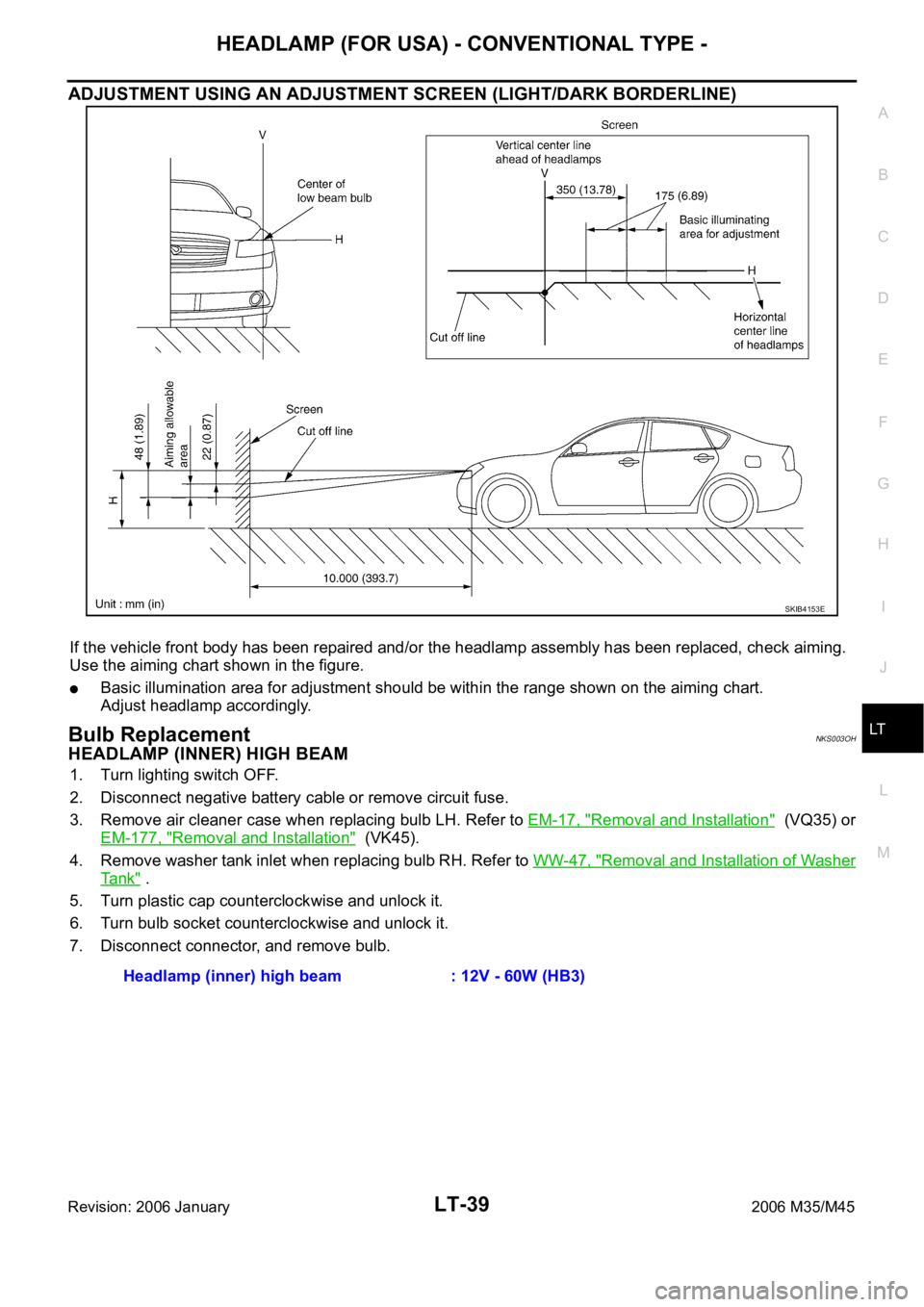
ADJUSTMENT USING AN ADJUSTMENT SCREEN (LIGHT/DARK BORDERLINE)
If the vehicle front body has been repaired and/or the headlamp assembly has been replaced, check aiming.
Use the aiming chart shown in the figure.
Basic illumination area for adjustment should be within the range shown on the aiming chart.
Adjust headlamp accordingly.
Bulb ReplacementNKS003OH
HEADLAMP (INNER) HIGH BEAM
1. Turn lighting switch OFF.
2. Disconnect negative battery cable or remove circuit fuse.
3. Remove air cleaner case when replacing bulb LH. Refer to EM-17, "
Removal and Installation" (VQ35) or
EM-177, "
Removal and Installation" (VK45).
4. Remove washer tank inlet when replacing bulb RH. Refer to WW-47, "
Removal and Installation of Washer
Ta n k" .
5. Turn plastic cap counterclockwise and unlock it.
6. Turn bulb socket counterclockwise and unlock it.
7. Disconnect connector, and remove bulb.
SKIB4153E
Headlamp (inner) high beam : 12V - 60W (HB3)
Page 4470 of 5621
HEADLAMP (FOR USA) - XENON TYPE -
LT-43
C
D
E
F
G
H
I
J
L
MA
B
LT
Revision: 2006 January2006 M35/M45
HEADLAMP (FOR USA) - XENON TYPE -PFP:26010
Component Parts and Harness Connector LocationNKS003OK
System DescriptionNKS003OL
The control of the headlamp system operation is dependent upon the position of the combination switch (light-
ing switch). When the lighting switch is placed in the 2ND position, the BCM (body control module) receives
input signal requesting the headlamps (and tail lamps) illuminate. This input signal is communicated to the
IPDM E/R (intelligent power distribution module engine room) across the CAN communication lines. The CPU
(central processing unit) located in the IPDM E/R controls the headlamp high and headlamp low relay coils.
These relays, when energized, direct power to the respective headlamps, which then illuminate.
PKIC0617E
Page 4502 of 5621

HEADLAMP (FOR USA) - XENON TYPE -
LT-75
C
D
E
F
G
H
I
J
L
MA
B
LT
Revision: 2006 January2006 M35/M45
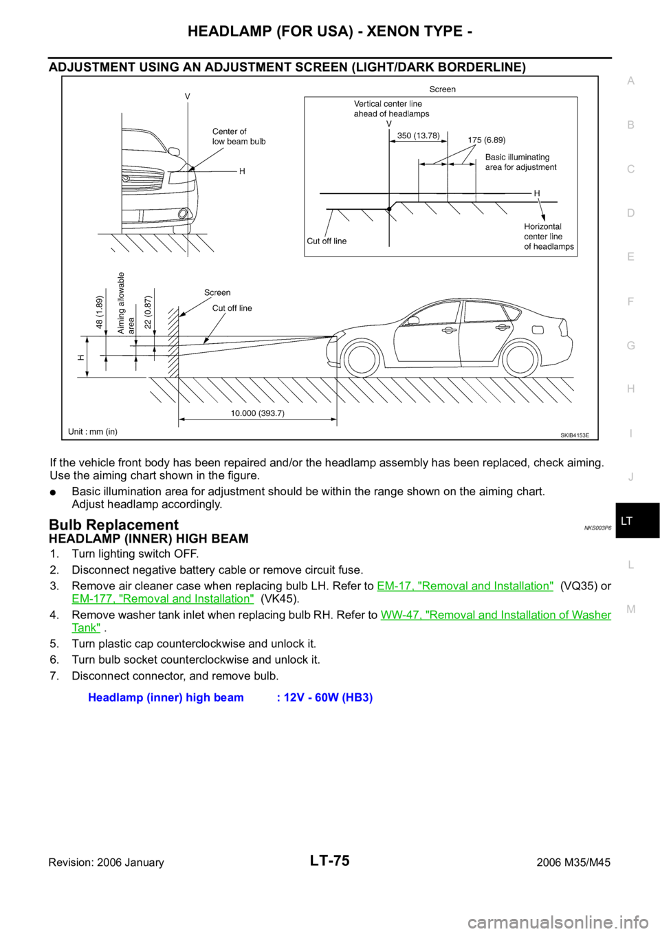
ADJUSTMENT USING AN ADJUSTMENT SCREEN (LIGHT/DARK BORDERLINE)
If the vehicle front body has been repaired and/or the headlamp assembly has been replaced, check aiming.
Use the aiming chart shown in the figure.
Basic illumination area for adjustment should be within the range shown on the aiming chart.
Adjust headlamp accordingly.
Bulb ReplacementNKS003P6
HEADLAMP (INNER) HIGH BEAM
1. Turn lighting switch OFF.
2. Disconnect negative battery cable or remove circuit fuse.
3. Remove air cleaner case when replacing bulb LH. Refer to EM-17, "
Removal and Installation" (VQ35) or
EM-177, "
Removal and Installation" (VK45).
4. Remove washer tank inlet when replacing bulb RH. Refer to WW-47, "
Removal and Installation of Washer
Ta n k" .
5. Turn plastic cap counterclockwise and unlock it.
6. Turn bulb socket counterclockwise and unlock it.
7. Disconnect connector, and remove bulb.
SKIB4153E
Headlamp (inner) high beam : 12V - 60W (HB3)
Page 4506 of 5621
HEADLAMP (FOR CANADA) - DAYTIME LIGHT SYSTEM -
LT-79
C
D
E
F
G
H
I
J
L
MA
B
LT
Revision: 2006 January2006 M35/M45
HEADLAMP (FOR CANADA) - DAYTIME LIGHT SYSTEM -PFP:26010
Component Parts and Harness Connector LocationNKS003P9
System DescriptionNKS003PA
DAYTIME LIGHT SYSTEM turns on daytime light lamps while driving. Daytime light lamps are not turned on if
engine is activated with parking brake on. Take off parking brake to turn on daytime light lamps. The lamps
turn off when lighting switch is in the 2ND position or AUTO position (Head lamp is “ON”) and when lighting
switch is in the PASSING position. (Daytime light lamps are not turned off only by parking brake itself.)
A parking brake signal and engine run or stop signal are sent to BCM (body control module) by CAN commu-
nication line, and control daytime light system.
PKIC0618E
Page 4543 of 5621
LT-116
AUTO LIGHT SYSTEM
Revision: 2006 January2006 M35/M45
AUTO LIGHT SYSTEMPFP:28491
Component Parts and Harness Connector LocationNKS003PY
System DescriptionNKS003PZ
Automatically turns ON/OFF the parking lamps and the headlamps in accordance with ambient light.
Timing for when lamps turn ON/OFF can be selected using four modes.
OUTLINE
The auto light control system has an optical sensor inside it that detects outside brightness.
When the lighting switch is in AUTO position, it automatically turns ON/OFF the parking lamps and the head-
lamps in accordance with ambient light. Sensitivity can be adjusted in four steps. For the details of the setting,
Refer to LT- 1 2 6 , "
SETTING CHANGE FUNCTIONS" .
Optical sensor, power is supplied
from BCM (body control module) terminal 17
PKIC0619E
Page 4618 of 5621
ACTIVE AFS
LT-191
C
D
E
F
G
H
I
J
L
MA
B
LT
Revision: 2006 January2006 M35/M45
Removal and Installation of AFS Control UnitNKS003QZ
REMOVAL
1. Remove dash side finisher RH. Refer to EI-37, "BODY SIDE TRIM" in EI section.
2. Remove screw (A).
3. Disconnect AFS control unit connector.
4. Remove AFS control unit (1).
INSTALLATION
Installation is the reverse order of removal.
Removal and Installation of AFS SwitchNKS003R0
REMOVAL
1. Remove instrument lower driver panel. Refer to IP-10, "INSTRUMENT PANEL ASSEMBLY" in IP section.
2. Press AFS switch fixing pawls (A) and remove unit (1) from
instrument lower driver panel.
INSTALLATION
Installation is the reverse order of removal.
SKIB4766E
SKIB4768E
Page 4620 of 5621
FRONT FOG LAMP
LT-193
C
D
E
F
G
H
I
J
L
MA
B
LT
Revision: 2006 January2006 M35/M45
FRONT FOG LAMPPFP:26150
Component Parts and Harness Connector LocationNKS003R2
System DescriptionNKS003R3
The control of the fog lamps is dependent upon the position of the combination switch (lighting switch). The
lighting switch must be in the 2ND position or AUTO position (headlamp is ON) for front fog lamp operation.
When the lighting switch is placed in fog lamp position, the BCM (body control module) receives input signal
requesting the fog lamps to illuminate. When the headlamps are illuminated, this input signal is communicated
to the IPDM E/R (intelligent power distribution module engine room) across the CAN communication lines. The
CPU (central processing unit) located in the IPDM E/R controls the front fog lamp relay coil. When activated,
this relay directs power to the front fog lamps.
PKIC0621E