2006 INFINITI M35 Starter motor
[x] Cancel search: Starter motorPage 352 of 5621

TRANSMISSION ASSEMBLY
AT-273
D
E
F
G
H
I
J
K
L
MA
B
AT
Revision: 2006 January2006 M35/M45
10. Remove crankshaft position sensor (POS) (1) from A/T assem-
bly.
CAUTION:
Do not subject it to impact by dropping or hitting it.
Do not disassemble.
Do not allow metal filings, etc., to get on the sensor's
front edge magnetic area.
Do not place in an area affected by magnetism.
11. Remove starter motor. Refer to SC-17, "
VQ35DE ENGINE
MODELS (2WD)" , SC-19, "VK45DE ENGINE MODELS" .
12. Remove rear cover plate. Refer to EM-29, "
Removal and Instal-
lation (2WD Models)" (for VQ35DE engine).
13. Remove rear plate cover. Refer to EM-29, "
Removal and Installation (2WD Models)" (for VQ35DE
engine), EM-187, "
Removal and Installation" (for VK45DE engine).
14. Turn crankshaft, and remove the four tightening bolts for drive
plate and torque converter.
CAUTION:
When turning the crankshaft, turn it clockwise as viewed
from the front of the engine.
15. Support A/T assembly with a transmission jack.
CAUTION:
When setting the transmission jack, be careful not to allow
it to collide against the drain plug.
16. Remove rear engine mounting member with power tool.
17. Remove engine mounting insulator (rear).
18. Disconnect A/T assembly harness connector.
19. Remove air breather hose. Refer to AT-269, "
Removal and Installation" .
20. Remove A/T fluid charging pipe from A/T assembly.
21. Remove O-ring from A/T fluid charging pipe.
22. Disconnect fluid cooler tube from A/T assembly.
23. Plug up openings such as the A/T fluid charging pipe hole, etc.
24. Remove bolts fixing A/T assembly to engine assembly with power tool.
25. Remove A/T assembly from vehicle.
CAUTION:
Secure torque converter to prevent it from dropping.
Secure A/T assembly to a transmission jack.
SCIA6506J
LCIA0335E
SCIA0499E
Page 355 of 5621

AT-276
TRANSMISSION ASSEMBLY
Revision: 2006 January2006 M35/M45
5. Remove heat insulator.
6. Remove rear propeller shaft. Refer to PR-8, "
Removal and Installation" .
7. Remove front cross bar with power tool. Refer to FSU-26, "
Removal and Installation" .
8. Remove exhaust mounting bracket. Refer to EX-5, "
Removal and Installation" .
9. Remove three way catalyst. Refer to EX-5, "
Removal and Installation" .
10. Remove front propeller shaft. Refer to PR-5, "
Removal and Installation" .
11. Remove control rod. Refer to AT-226, "
Control Rod Removal and Installation" .
12. Remove crankshaft position sensor (POS) (1) from A/T assem-
bly.
CAUTION:
Do not subject it to impact by dropping or hitting it.
Do not disassemble.
Do not allow metal filings, etc., to get on the sensor's
front edge magnetic area.
Do not place in an area affected by magnetism.
13. Remove starter motor. Refer to SC-18, "
VQ35DE ENGINE
MODELS (AWD)" .
14. Remove rear plate cover. Refer to EM-36, "
Removal and Instal-
lation (AWD Models)" .
15. Turn crankshaft, and remove the four tightening bolts for drive
plate and torque converter.
CAUTION:
When turning the crankshaft, turn it clockwise as viewed
from the front of the engine.
16. Support A/T assembly with a transmission jack.
CAUTION:
When setting the transmission jack, be careful not to allow
it to collide against the drain plug.
17. Remove rear engine mounting member with power tool.
18. Remove engine mounting insulator (rear).
19. Disconnect A/T assembly harness connector.
20. Remove air breather hose. Refer to AT- 2 6 9 , "
Removal and Installation" .
21. Remove A/T fluid charging pipe from A/T assembly.
22. Remove O-ring from A/T fluid charging pipe.
23. Disconnect fluid cooler tube from the A/T assembly.
24. Plug up openings such as the A/T fluid charging pipe hole, etc.
25. Remove bolts fixing A/T assembly to engine assembly with power tool.
26. Remove A/T assembly with transfer assembly from vehicle.
CAUTION:
Secure torque converter to prevent it from dropping.
Secure A/T assembly to a transmission jack.
27. Remove transfer assembly from A/T assembly with power tool.
SCIA6506J
LCIA0335E
SCIA2203E
Page 1068 of 5621

INTELLIGENT KEY SYSTEM/ENGINE START FUNCTION
BL-129
C
D
E
F
G
H
J
K
L
MA
B
BL
Revision: 2006 January2006 M35/M45
PRECAUTIONS FOR INTELLIGENT KEY SYSTEM
In the Intelligent Key system of model Y50, the transponder (the chip for immobilizer ID verifica-
tion) is integrated into the Intelligent Key. (For the conventional models, it is integrated into the
mechanical key.) Therefore, the mechanical key cannot perform the ID verification, and thus it can-
not start the engine. Instead of it, the immobilizer ID verification can be performed by inserting the
Intelligent Key into the key slot, and then it can start the engine.
When registering the Intelligent Key, 2 registration procedures (immobilizer ID registration and
Intelligent Key ID registration) should be performed. The immobilizer ID registration is the proce-
dure that registers the ID stored into the transponder (integrated into Intelligent Key) to the BCM.
The Intelligent Key ID registration is the procedure that registers the ID to the Intelligent Key unit.
Each registration is a different procedure.
When performing the Intelligent Key ID registration only, the engine cannot be started by inserting
the key into the key slot. When performing the engine immobilizer ID registration only, the engine
cannot be started by the operation when carrying the key. The registrations of both systems
should be performed.
Operation DescriptionNIS001Y9
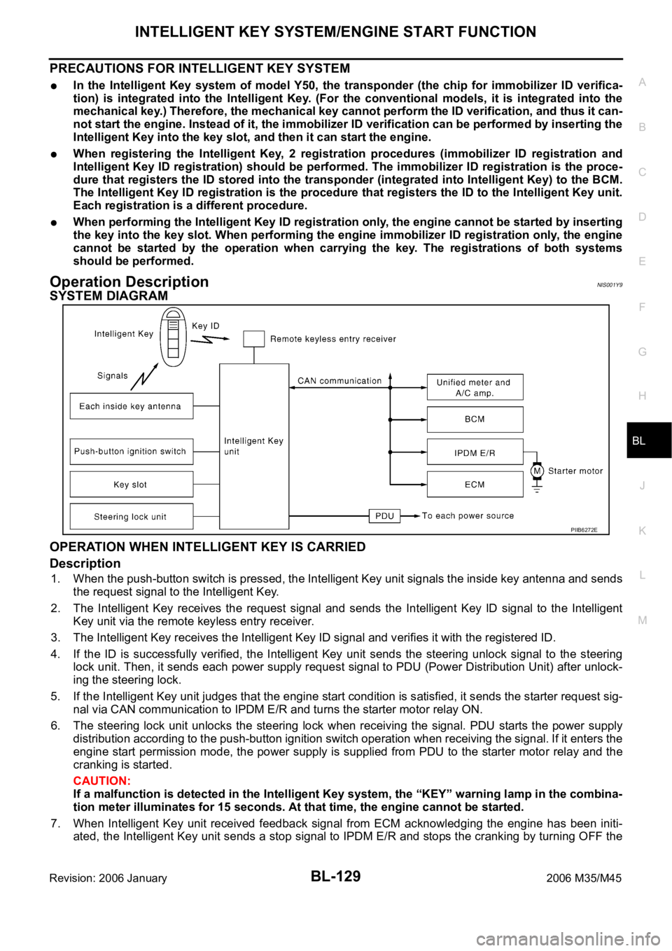
SYSTEM DIAGRAM
OPERATION WHEN INTELLIGENT KEY IS CARRIED
Description
1. When the push-button switch is pressed, the Intelligent Key unit signals the inside key antenna and sends
the request signal to the Intelligent Key.
2. The Intelligent Key receives the request signal and sends the Intelligent Key ID signal to the Intelligent
Key unit via the remote keyless entry receiver.
3. The Intelligent Key receives the Intelligent Key ID signal and verifies it with the registered ID.
4. If the ID is successfully verified, the Intelligent Key unit sends the steering unlock signal to the steering
lock unit. Then, it sends each power supply request signal to PDU (Power Distribution Unit) after unlock-
ing the steering lock.
5. If the Intelligent Key unit judges that the engine start condition is satisfied, it sends the starter request sig-
nal via CAN communication to IPDM E/R and turns the starter motor relay ON.
6. The steering lock unit unlocks the steering lock when receiving the signal. PDU starts the power supply
distribution according to the push-button ignition switch operation when receiving the signal. If it enters the
engine start permission mode, the power supply is supplied from PDU to the starter motor relay and the
cranking is started.
CAUTION:
If a malfunction is detected in the Intelligent Key system, the “KEY” warning lamp in the combina-
tion meter illuminates for 15 seconds. At that time, the engine cannot be started.
7. When Intelligent Key unit received feedback signal from ECM acknowledging the engine has been initi-
ated, the Intelligent Key unit sends a stop signal to IPDM E/R and stops the cranking by turning OFF the
PIIB6272E
Page 1069 of 5621

BL-130
INTELLIGENT KEY SYSTEM/ENGINE START FUNCTION
Revision: 2006 January2006 M35/M45
starter motor relay. (If the engine initiating has failed, the cranking will stop automatically within 5 sec-
onds.)
CAUTION:
When the Intelligent Key is carried outside of the vehicle (inside key antenna detection area) with
the power supply in ACC or ON position, even if the engine start condition* is satisfied, the engine
cannot be started.
*: For the engine start condition, refer to BL-130, "
PUSH-BUTTON IGNITION SWITCH OPERATION PROCE-
DURE" .
Operation Range
Engine can be started when Intelligent Key is inside the vehicle. However, sometimes engine might not start
when Intelligent Key is on instrument panel or in glove box.
OPERATION WHEN KEY SLOT IS USED
When the Intelligent Key battery is discharged, it performs the immobilizer ID verification between the inte-
grated transponder and BCM by inserting the Intelligent Key into the key slot, and then the engine can be
started.
For details relating to starting the engine using key slot, refer to BL-248, "
IVIS (INFINITI VEHICLE IMMOBI-
LIZER SYSTEM-NATS)" .
PUSH-BUTTON IGNITION SWITCH OPERATION PROCEDURE
The power supply position changing operation can be performed with the following operation.
NOTE:
When an Intelligent Key is within the detection area of inside key antenna and when it is inserted to the
key slot, it is equivalent to the operations below.
When starting the engine, the Intelligent Key unit monitors the engine start conditions (brake pedal operat-
ing condition, A/T selector lever position, and vehicle speed).
Unless each start condition is fulfilled, the engine will not respond regardless of how many times the
engine switch is pushed. At that time, illumination repeats the position in the order of LOCK
AC-
C
ONLOCK.
Power supply positionEngine start/stop condition
Push-button ignition switch
operation frequency
Brake pedal A/T selector lever position
LOCK
ACCNot depressed
(When A/T selector lever is in any
position other than P or N, there
will be no effect even if it is
depressed.)Any position other than P or N
(When the brake pedal is not
depressed, there will be no effect
even if the A/T selector lever is in
P or N position.)1
LOCK
ACC ONNot depressed
(When A/T selector lever is in any
position other than P or N, there
will be no effect even if it is
depressed.)Any position other than P or N
(When the brake pedal is not
depressed, there will be no effect
even if the A/T selector lever is in
P or N position.)2
LOCK
ACC ON
LOCKNot depressed
(When A/T selector lever is in any
position other than P or N, there
will be no effect even if it is
depressed.)Any position other than P or N
(When the brake pedal is not
depressed, there will be no effect
even if the A/T selector lever is in
P or N position.)3
LOCK
START
ACC
START
ON
START
(Engine start)Depressed P or N position (*1)1
[If the switch is pushed once,
the engine starts from any
power supply position (LOCK,
ACC, and ON)]
Engine is running
LOCK
(Engine stop)— P position 1
Page 1084 of 5621

INTELLIGENT KEY SYSTEM/ENGINE START FUNCTION
BL-145
C
D
E
F
G
H
J
K
L
MA
B
BL
Revision: 2006 January2006 M35/M45
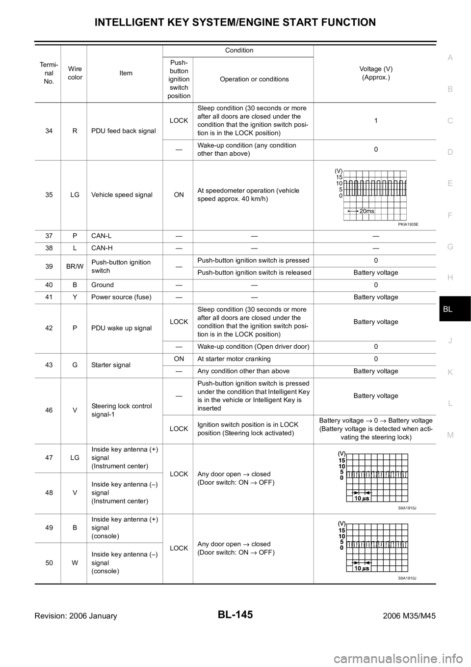
34 R PDU feed back signalLOCKSleep condition (30 seconds or more
after all doors are closed under the
condition that the ignition switch posi-
tion is in the LOCK position)1
—Wake-up condition (any condition
other than above)0
35 LG Vehicle speed signal ONAt speedometer operation (vehicle
speed approx. 40 km/h)
37 P CAN-L — — —
38 L CAN-H — — —
39 BR/WPush-button ignition
switch—Push-button ignition switch is pressed 0
Push-button ignition switch is released Battery voltage
40 B Ground — — 0
41 Y Power source (fuse) — — Battery voltage
42 P PDU wake up signalLOCKSleep condition (30 seconds or more
after all doors are closed under the
condition that the ignition switch posi-
tion is in the LOCK position)Battery voltage
— Wake-up condition (Open driver door) 0
43 G Starter signalON At starter motor cranking 0
— Any condition other than above Battery voltage
46 VSteering lock control
signal-1—Push-button ignition switch is pressed
under the condition that Intelligent Key
is in the vehicle or Intelligent Key is
insertedBattery voltage
LOCKIgnition switch position is in LOCK
position (Steering lock activated)Battery voltage
0 Battery voltage
(Battery voltage is detected when acti-
vating the steering lock)
47 LGInside key antenna (+)
signal
(Instrument center)
LOCK Any door open
closed
(Door switch: ON
OFF)
48 VInside key antenna (–)
signal
(Instrument center)
49 BInside key antenna (+)
signal
(console)
LOCKAny door open
closed
(Door switch: ON
OFF)
50 WInside key antenna (–)
signal
(console) Te r m i -
nal
No.Wire
colorItemCondition
Voltage (V)
(Approx.) Push-
button
ignition
switch
positionOperation or conditions
PKIA1935E
SIIA1910J
SIIA1910J
Page 1086 of 5621

INTELLIGENT KEY SYSTEM/ENGINE START FUNCTION
BL-147
C
D
E
F
G
H
J
K
L
MA
B
BL
Revision: 2006 January2006 M35/M45
Terminals and Reference Value for BCMNIS001YG
Terminals and Reference Value for IPDM E/RNIS001YH
6 B Ground — — 0
7 LG Power source LOCK — Battery voltage
8 L/Y Condition signal-2LOCK Steering lock: Lock Battery voltage
ACC
Steering lock: Unlock0
ON 0 Termi-
nal
No.Wire
colorItemCondition
Voltage (V)
(Approx.) Push-
button
ignition
switch
positionOperation or conditions
Te r m i -
nal
No.Wire
colorItemCondition
Voltage (V)
(Approx.) Push-but-
ton igni-
tion
switch
positionOperation or conditions
23 W/V Security indicator LOCKIntelligent Key is removed from key
slot and power supply position is in
LOCK positionBattery voltage
0
(Every 2.4 seconds)
37 LGKey slot
(Key switch signal)LOCKIntelligent Key is removed from key
slot0
Intelligent Key is inserted into key slot Battery voltage
38 WIgnition power supply
(ON or START)ONPower supply position is in ON posi-
tionBattery voltage
39 L CAN-H — — —
40 P CAN-L — — —
42 P Power source (fuse) — — Battery voltage
52 B Ground — — 0
55 WPower source (Fusil-
lade link)— — Battery voltage
Te r -
minal
No.Wire
ColorItemCondition
Voltage (V)
(Approx.) Push-
button
ignition
switch
positionOperation or conditions
4W/RStarter motor power
supplyLOCK — 0
START Starter motor is activating Battery voltage
49 L CAN H — — —
50 P CAN L — — —
53 GR/R Shift position signalONA/T selector lever is in N or P
positionBattery voltage
LOCKA/T selector lever is in any
position other than P and N
position0
Page 1087 of 5621

BL-148
INTELLIGENT KEY SYSTEM/ENGINE START FUNCTION
Revision: 2006 January2006 M35/M45
Terminals and Reference Value for PDUNIS001YI
Te r -
minal
No.Wire
colorItemCondition
Voltage (V)
(Approx.) Push-
button
ignition
switch
positionOperation or conditions
1 P Wake up signalLOCKSleep condition (30 seconds or more
after all doors are closed under the con-
dition that the power supply position is in
the LOCK position)Battery voltage
— Wake-up condition (Open driver door) 0
2 G Starter control signalON At starter motor cranking 0
— Any condition other than above Battery voltage
3GRSteering lock unit
power sourceLOCKPush-button ignition switch is pressed
under the condition that Intelligent Key is
in the vehicle or Intelligent Key is inserted0
Battery voltage 0
— Any condition other than above 0
6VSteering lock control
signal-1—Push-button ignition switch is pressed
under the condition that Intelligent Key is
in the vehicle or Intelligent Key is insertedBattery voltage
LOCKPower supply position is in LOCK posi-
tion
(Steering lock activated)Battery voltage
0 Battery volt-
age
(Battery voltage is detected when
activating the steering lock)
7LGSteering lock control
signal-2—Push-button ignition switch is pressed
under the condition that Intelligent Key is
in the vehicle or Intelligent Key is insertedBattery voltage
LOCKPower supply position is in LOCK posi-
tion
(Steering lock activated)Battery voltage
0 Battery volt-
age
(Battery voltage is detected when
activating the steering lock)
9OSteering lock feed
back signal— Steering lock: Lock 0
LOCK Steering lock: Unlock 8
10 B Ground — — 0
11 YIPDM E/R current sig-
nalSTART At starter motor cranking 5
LOCK Any condition other than above 2
12 R Feed back signalLOCKSleep condition (30 seconds or more
after all doors are closed under the con-
dition that the power supply position is in
the LOCK position)1
—Wake-up condition (any condition other
than above)0
13 R Starter relaySTART At starter motor cranking Battery voltage
— Any condition other than above 4
14 SB Power source (fuse) — — Battery voltage
15 LPower source (fusible
link)— — Battery voltage
17 GPower source (fusible
link)— — Battery voltage
Page 1113 of 5621

BL-174
INTELLIGENT KEY SYSTEM/ENGINE START FUNCTION
Revision: 2006 January2006 M35/M45
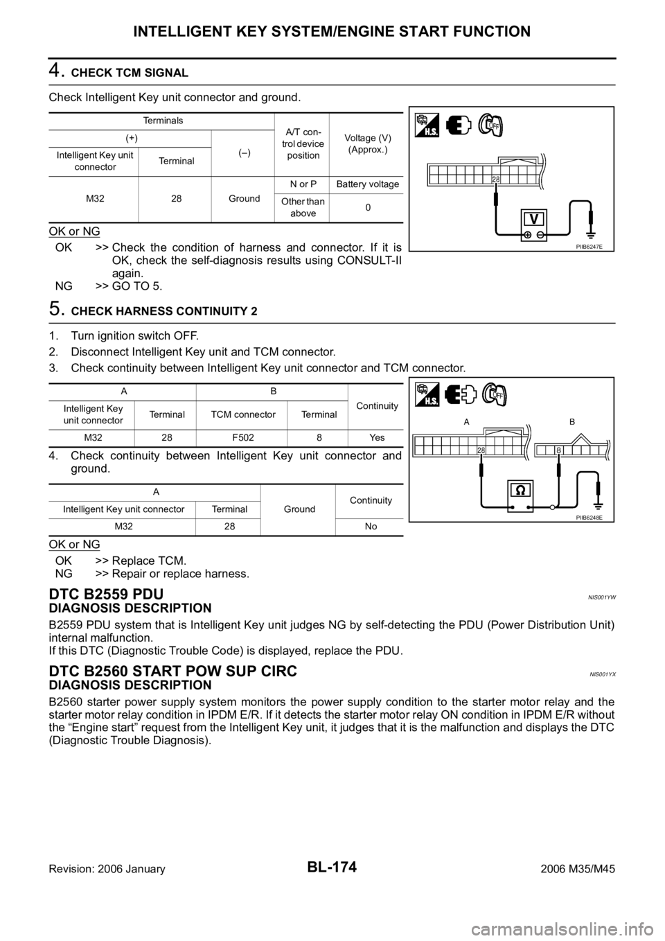
4. CHECK TCM SIGNAL
Check Intelligent Key unit connector and ground.
OK or NG
OK >> Check the condition of harness and connector. If it is
OK, check the self-diagnosis results using CONSULT-II
again.
NG >> GO TO 5.
5. CHECK HARNESS CONTINUITY 2
1. Turn ignition switch OFF.
2. Disconnect Intelligent Key unit and TCM connector.
3. Check continuity between Intelligent Key unit connector and TCM connector.
4. Check continuity between Intelligent Key unit connector and
ground.
OK or NG
OK >> Replace TCM.
NG >> Repair or replace harness.
DTC B2559 PDUNIS001YW
DIAGNOSIS DESCRIPTION
B2559 PDU system that is Intelligent Key unit judges NG by self-detecting the PDU (Power Distribution Unit)
internal malfunction.
If this DTC (Diagnostic Trouble Code) is displayed, replace the PDU.
DTC B2560 START POW SUP CIRCNIS001YX
DIAGNOSIS DESCRIPTION
B2560 starter power supply system monitors the power supply condition to the starter motor relay and the
starter motor relay condition in IPDM E/R. If it detects the starter motor relay ON condition in IPDM E/R without
the “Engine start” request from the Intelligent Key unit, it judges that it is the malfunction and displays the DTC
(Diagnostic Trouble Diagnosis).
Terminals
A/T con-
trol device
positionVoltage (V)
(Approx.) (+)
(–)
Intelligent Key unit
connectorTerminal
M32 28 GroundN or P Battery voltage
Other than
above0
PIIB6247E
AB
Continuity
Intelligent Key
unit connectorTerminal TCM connector Terminal
M32 28 F502 8 Yes
A
GroundContinuity
Intelligent Key unit connector Terminal
M32 28 No
PIIB6248E