2006 INFINITI M35 Starter motor
[x] Cancel search: Starter motorPage 3714 of 5621
![INFINITI M35 2006 Factory Service Manual CAN COMMUNICATION
LAN-45
[CAN]
C
D
E
F
G
H
I
J
L
MA
B
LAN
Revision: 2006 January2006 M35/M45
ACC signal T R R
Blower fan motor switch signal R T
Buzzer output signalTR
TR
RT
Day time running light req INFINITI M35 2006 Factory Service Manual CAN COMMUNICATION
LAN-45
[CAN]
C
D
E
F
G
H
I
J
L
MA
B
LAN
Revision: 2006 January2006 M35/M45
ACC signal T R R
Blower fan motor switch signal R T
Buzzer output signalTR
TR
RT
Day time running light req](/manual-img/42/57023/w960_57023-3713.png)
CAN COMMUNICATION
LAN-45
[CAN]
C
D
E
F
G
H
I
J
L
MA
B
LAN
Revision: 2006 January2006 M35/M45
ACC signal T R R
Blower fan motor switch signal R T
Buzzer output signalTR
TR
RT
Day time running light request signal T R
Door lock/unlock status signal T R
Door switch signal T R R R R R
Door unlock signal T R
Front fog light request signal T R R
Front wiper request signal T R R
High beam request signal T R R
Ignition switch ON signal T R R
Ignition switch signal T R R
Key ID signal T R
Key switch signal T R
Low beam request signal T R
Position light request signal T R R
Rear window defogger switch signal T R
Sleep wake up signal T R R R R
Starter request signal T R
Theft warning horn request signal T R
Trunk switch signal T R R
Turn indicator signal T R R
Tire pressure data signal T R
Tire pressure signal T R R
Steering angle sensor signal R T R
Door lock/unlock trunk open request signal R T
Hazard and horn request signal R T
Key warning signalTR
Meter display signalTR
RT
Panic alarm request signal R T
Power window open request signal R TSignals
ECM
TCM
AWD control unit
AFS control unit*1
BCM
LDW camera unit*2
Low tire pressure warning control unit
Steering angle sensor
Intelligent Key unit
Unified meter and A/C amp.
AV (NAVI) control unit
Pre-crash seat belt control unit*3
Driver seat control unit
ABS actuator and electric unit (control unit)
ICC sensor integrated unit*4
IPDM E/R
Page 4845 of 5621

PG-18
IPDM E/R (INTELLIGENT POWER DISTRIBUTION MODULE ENGINE ROOM)
Revision: 2006 January2006 M35/M45
IPDM E/R (INTELLIGENT POWER DISTRIBUTION MODULE ENGINE ROOM)
PFP:284B7
System DescriptionNKS004E2
IPDM E/R (Intelligent Power Distribution Module Engine Room) integrates the relay box and fuse block
which were originally placed in engine compartment. It controls integrated relay via IPDM E/R control cir-
cuit.
IPDM E/R-integrated control circuit performs ON-OFF operation of relay, CAN communication control and
oil pressure switch signal reception, etc.
It controls operation of each electrical part via ECM, BCM and CAN communication lines.
CAUTION:
None of the IPDM E/R-integrated relays can be removed.
SYSTEMS CONTROLLED BY IPDM E/R
1. Lamp control
Using CAN communication, it receives signal from BCM and controls the following lamps:
Headlamps (HI, LO)
Tail, parking and license plate lamps
Front fog lamps
2. Daytime light relay control (for Canada models)
Using CAN communication, it receives signals from BCM and controls the daytime light relay.
3. Wiper control
Using CAN communication, it receives signals from BCM and controls the front wipers.
4. Rear window defogger relay control
Using CAN communication, it receives signals from BCM and controls the rear window defogger relay.
5. A/C compressor control
Using CAN communication, it receives signals from ECM and controls the A/C relay.
6. Cooling fan control
Using CAN communication, it receives signals from ECM and controls cooling fan via cooling fan control
module.
7. Horn control
Using CAN communication, it receives signals from BCM and controls horn relay.
8. Starter motor relay control
Using CAN communication, it receives signals from BCM and controls starter motor relay.
9. Alternator control
Using CAN communication, it receives signal from ECM and controls power generation voltage.
CAN COMMUNICATION LINE CONTROL
With CAN communication, by connecting each control unit using two communication lines (CAN L-line, CAN
H-line), it is possible to transmit maximum amount of information with minimum wiring. Each control unit can
transmit and receive data, and reads necessary information only.
1. Fail-safe control
When CAN communication with other control units is impossible, IPDM E/R performs fail-safe control.
After CAN communication recovers normally, it also returns to normal control.
Operation of control parts by IPDM E/R during fail-safe mode is as follows:
Controlled system Fail-safe mode
Headlamps
With the ignition switch ON, the headlamp low relay is ON.
With the ignition switch OFF, the headlamp low relay is OFF.
Tail, parking and
license plate lamps
With the ignition switch ON, the tail lamp relay is ON.
With the ignition switch OFF, the tail lamp relay is OFF.
Cooling fan
With the ignition switch ON, the cooling fan HI operates.
With the ignition switch OFF, the cooling fan stops.
Front wiperUntil the ignition switch is turned off, the front wiper LO and HI remains in the same status it was in just
before fail
safe control was initiated.
Page 4849 of 5621

PG-22
IPDM E/R (INTELLIGENT POWER DISTRIBUTION MODULE ENGINE ROOM)
Revision: 2006 January2006 M35/M45
DATA MONITOR
Operation Procedure
1. Touch “DATA MONITOR” on “SELECT MONITOR ITEM ” screen.
2. Touch “ALL SIGNALS”, “MAIN SIGNALS” or “SELECTION FROM MENU” on the “DATA MONITOR”
screen.
3. Touch the required monitoring item on “SELECTION FROM MENU”. In “ALL SIGNALS”, all items are
monitored. In “MAIN SIGNALS”, predetermined items are monitored.
4. Touch “START”.
5. Touch “RECORD” while monitoring to record the status of the item being monitored. To stop recording,
touch “STOP”.
All Signals, Main Signals, Selection From Menu
NOTE:
Perform monitoring of IPDM E/R data with the ignition switch ON. When the ignition switch is at ACC, the display may not be cor-
rect.
*1: Only the vehicle with day time light system operates. ALL SIGNALS All items will be monitored.
MAIN SIGNALS Monitor the predetermined item.
SELECTION FROM MENU Select any item for monitoring.
Item nameCONSULT-II
screen displayDisplay or unitMonitor item selection
Description
ALL
SIGNALSMAIN
SIGNALSSELECTION
FROM
MENU
Motor fan request MOTOR FAN REQ 1/2/3/4
Signal status input from ECM
A/C Compressor
requestAC COMP REQ ON/OFF
Signal status input from ECM
Tail & clearance
requestTAIL&CLR REQ ON/OFF
Signal status input from BCM
Headlamp LO
requestHL LO REQ ON/OFF
Signal status input from BCM
Headlamp HI
requestHL HI REQ ON/OFF
Signal status input from BCM
Front fog lamp
request FR FOG REQ ON/OFF
Signal status input from BCM
Front wiper request FR WIP REQSTOP/1LOW/
LOW/HI
Signal status input from BCM
Wiper auto stop WIP AUTO STOP ACT P/STOP P
Output status of IPDM E/R
Wiper protection WIP PROT OFF/BLOCK
Control status of IPDM E/R
Starter request ST RLY REQ ON/OFF
Signal status input from BCM
Ignition relay status IGN RLY ON/OFF
Ignition relay status monitored
with IPDM E/R
Rear window defog-
ger requestRR DEF REQ ON/OFF
Signal status input from BCM
Oil pressure switch OIL P SW OPEN/CLOSE
Signal status input in IPDM E/R
Daytime running
light requestDTRL REQ
*1ON/OFFSignal status input from BCM
Hood switch HOOD SW ON/OFF
Signal status input in IPDM E/R
Theft warning horn
requestTHFT HRN REQ ON/OFF
Signal status input from BCM
Horn chirp HORN CHIRP ON/OFF
Output status of IPDM E/R
Page 5147 of 5621

SC-10
STARTING SYSTEM
Revision: 2006 January2006 M35/M45
STARTING SYSTEM PFP:00011
System Description NKS003NI
Power is supplied at all times
through 15A fuse (No. 78, located in the IPDM E/R)
to CPU of IPDM E/R,
through 15A fuse (No. 71, located in the IPDM E/R)
to CPU of IPDM E/R.
Ground is supplied
to IPDM E/R terminals 38 and 51
from grounds E22 and E43.
When the selector lever in the P or N position, power is supplied
from TCM, and through A/T assembly terminal 9
to IPDM E/R terminal 53.
And then provided that IPDM E/R receives a starter relay ON signal with CAN communication, starter relay is
energized.
With the ignition switch in the START position, power is supplied
through IPDM E/R terminal 3
to starter motor terminal 1.
The starter motor plunger closes and provides a closed circuit between the battery and starter motor. The
starter motor is grounded to the engine block. With power and ground supplied, cranking occurs and the
engine starts.
Page 5152 of 5621

STARTING SYSTEM
SC-15
C
D
E
F
G
H
I
J
L
MA
B
SC
Revision: 2006 January2006 M35/M45
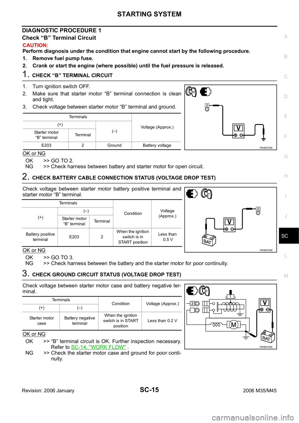
DIAGNOSTIC PROCEDURE 1
Check “B” Terminal Circuit
CAUTION:
Perform diagnosis under the condition that engine cannot start by the following procedure.
1. Remove fuel pump fuse.
2. Crank or start the engine (where possible) until the fuel pressure is released.
1. CHECK “B” TERMINAL CIRCUIT
1. Turn ignition switch OFF.
2. Make sure that starter motor “B” terminal connection is clean
and tight.
3. Check voltage between starter motor “B” terminal and ground.
OK or NG
OK >> GO TO 2.
NG >> Check harness between battery and starter motor for open circuit.
2. CHECK BATTERY CABLE CONNECTION STATUS (VOLTAGE DROP TEST)
Check voltage between starter motor battery positive terminal and
starter motor “B” terminal.
OK or NG
OK >> GO TO 3.
NG >> Check harness between the battery and the starter motor for poor continuity.
3. CHECK GROUND CIRCUIT STATUS (VOLTAGE DROP TEST)
Check voltage between starter motor case and battery negative ter-
minal.
OK or NG
OK >> “B” terminal circuit is OK. Further inspection necessary.
Refer to SC-14, "
WORK FLOW" .
NG >> Check the starter motor case and ground for poor conti-
nuity.
Terminals
Voltage (Approx.) (+)
(–)
Starter motor
“B” terminalTerminal
E203 2 Ground Battery voltage
PKIB8793E
Terminals
ConditionVoltage
(Approx.)
(+)(–)
Starter motor
“B” terminalTerminal
Battery positive
terminalE203 2 When the ignition
switch is in
START positionLess than
0.5 V
PKIB8794E
Terminals
Condition Voltage (Approx.)
(+) (–)
Starter motor
caseBattery negative
terminalWhen the ignition
switch is in START
positionLess than 0.2 V
PKIB8795E
Page 5153 of 5621

SC-16
STARTING SYSTEM
Revision: 2006 January2006 M35/M45
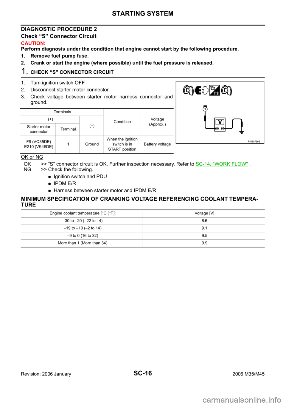
DIAGNOSTIC PROCEDURE 2
Check “S” Connector Circuit
CAUTION:
Perform diagnosis under the condition that engine cannot start by the following procedure.
1. Remove fuel pump fuse.
2. Crank or start the engine (where possible) until the fuel pressure is released.
1. CHECK “S” CONNECTOR CIRCUIT
1. Turn ignition switch OFF.
2. Disconnect starter motor connector.
3. Check voltage between starter motor harness connector and
ground.
OK or NG
OK >> “S” connector circuit is OK. Further inspection necessary. Refer to SC-14, "WORK FLOW" .
NG >> Check the following.
Ignition switch and PDU
IPDM E/R
Harness between starter motor and IPDM E/R
MINIMUM SPECIFICATION OF CRANKING VOLTAGE REFERENCING COOLANT TEMPERA-
TURE
Te r m i n a l s
ConditionVoltage
(Approx.) (+)
(–)
Starter motor
connectorTe r m i n a l
F9 (VQ35DE)
E210 (VK45DE)1 GroundWhen the ignition
switch is in
START positionBattery voltage
PKIB8796E
Engine coolant temperature [C (F)] Voltage [V]
30 to 20 (22 to 4) 8.6
19 to 10 (2 to 14) 9.1
9 to 0 (16 to 32) 9.5
More than 1 (More than 34) 9.9
Page 5154 of 5621

STARTING SYSTEM
SC-17
C
D
E
F
G
H
I
J
L
MA
B
SC
Revision: 2006 January2006 M35/M45
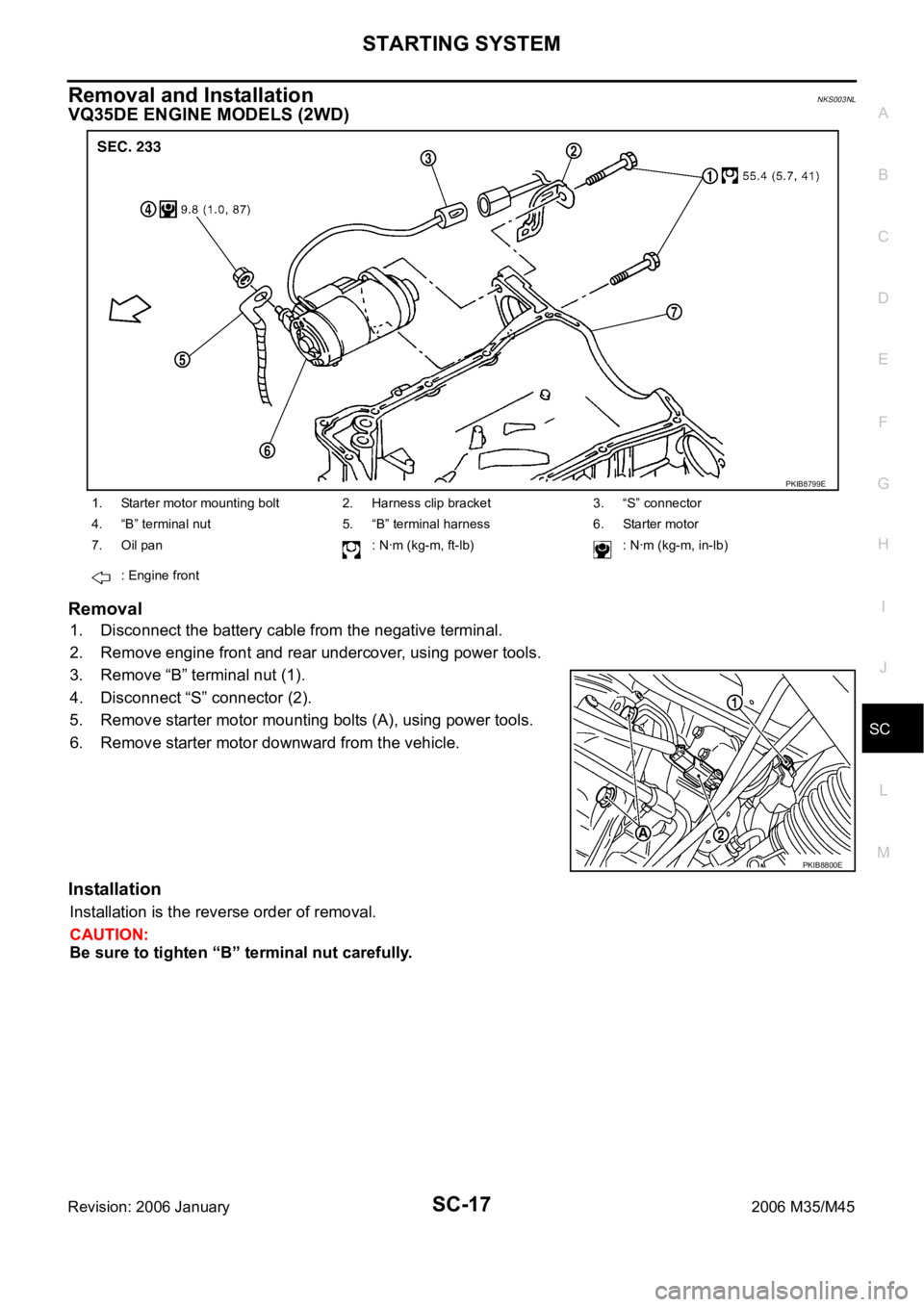
Removal and Installation NKS003NL
VQ35DE ENGINE MODELS (2WD)
Removal
1. Disconnect the battery cable from the negative terminal.
2. Remove engine front and rear undercover, using power tools.
3. Remove “B” terminal nut (1).
4. Disconnect “S” connector (2).
5. Remove starter motor mounting bolts (A), using power tools.
6. Remove starter motor downward from the vehicle.
Installation
Installation is the reverse order of removal.
CAUTION:
Be sure to tighten “B” terminal nut carefully.
1. Starter motor mounting bolt 2. Harness clip bracket 3. “S” connector
4. “B” terminal nut 5. “B” terminal harness 6. Starter motor
7. Oil pan : Nꞏm (kg-m, ft-lb) : Nꞏm (kg-m, in-lb)
: Engine front
PKIB8799E
PKIB8800E
Page 5155 of 5621

SC-18
STARTING SYSTEM
Revision: 2006 January2006 M35/M45
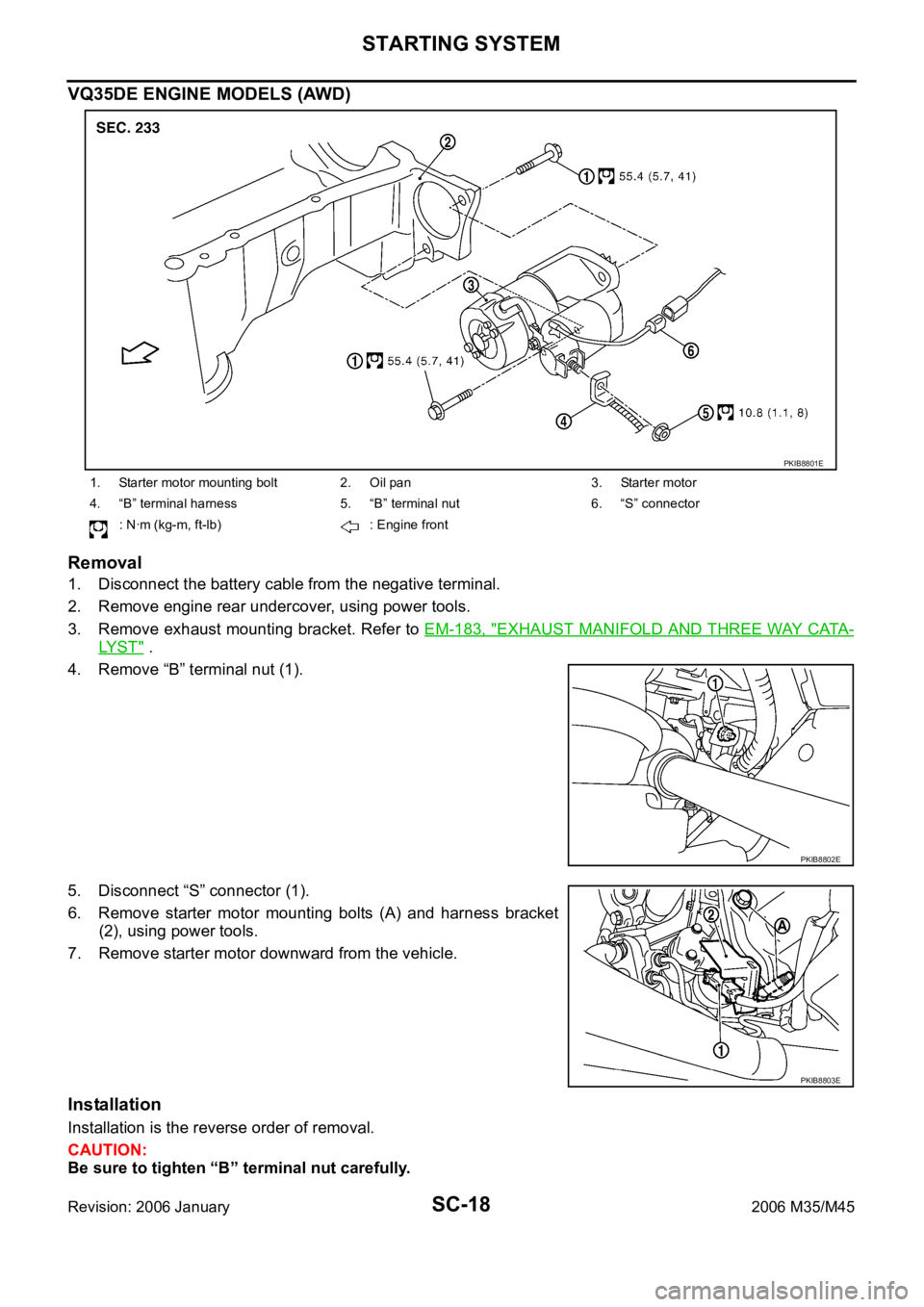
VQ35DE ENGINE MODELS (AWD)
Removal
1. Disconnect the battery cable from the negative terminal.
2. Remove engine rear undercover, using power tools.
3. Remove exhaust mounting bracket. Refer to EM-183, "
EXHAUST MANIFOLD AND THREE WAY CATA-
LY S T" .
4. Remove “B” terminal nut (1).
5. Disconnect “S” connector (1).
6. Remove starter motor mounting bolts (A) and harness bracket
(2), using power tools.
7. Remove starter motor downward from the vehicle.
Installation
Installation is the reverse order of removal.
CAUTION:
Be sure to tighten “B” terminal nut carefully.
1. Starter motor mounting bolt 2. Oil pan 3. Starter motor
4. “B” terminal harness 5. “B” terminal nut 6. “S” connector
: Nꞏm (kg-m, ft-lb) : Engine front
PKIB8801E
PKIB8802E
PKIB8803E