2006 INFINITI M35 Body
[x] Cancel search: BodyPage 5297 of 5621

SE-116
CLIMATE CONTROLLED SEAT
Revision: 2006 January2006 M35/M45
through climate controlled seat control unit terminal 16,
ground is supplied
to climate controlled seat control unit terminal 15,
through seatback thermal electric device terminal 4,
through climate controlled seat control unit terminal 3,
through body grounds B5, B40 and B131.
When climate controlled switch selects HEAT,
Power is supplied
to climate controlled seat switch terminal 5,
through climate controlled seat control unit terminal 8.
Ground is supplied
to the climate controlled seat switch terminal 6,
through body grounds B5, B40 and B131.
Then climate controlled seat switch HEAT indicator is energized.
When climate controlled switch select COOL,
Power is supplied
to climate controlled seat switch terminal 4,
through climate controlled seat control unit terminal 9.
Ground is supplied
to the climate controlled seat switch terminal 6,
through body grounds B5, B40 and B131.
Then climate controlled seat switch COOL indicator is energized.
Page 5305 of 5621

SE-124
CLIMATE CONTROLLED SEAT
Revision: 2006 January2006 M35/M45
Work FlowNIS0027M
1. Check the symptom and customer's requests.
2. Understand the outline of system. Refer to SE-113, "
System Description" .
3. Perform the preliminary check. Refer toSE-124, "
Preliminary Check" .
4. According to the trouble diagnosis chart, repair or replace the cause of the malfunction. Refer to SE-125,
"Trouble Diagnoses Symptom Chart" .
5. Does climate controlled seat operate normally? YES: GO TO 6, NO: GO TO 4.
6. INSPECTION END.
Preliminary CheckNIS0027N
1. CHECK DUCT AND FILTER
Check the following.
Is that there no foreign body in the blower motor filter.
Is that there no foreign body in the duct.
OK or NG
OK >> Preliminary check is OK.
NG >> The foreign body is removed.
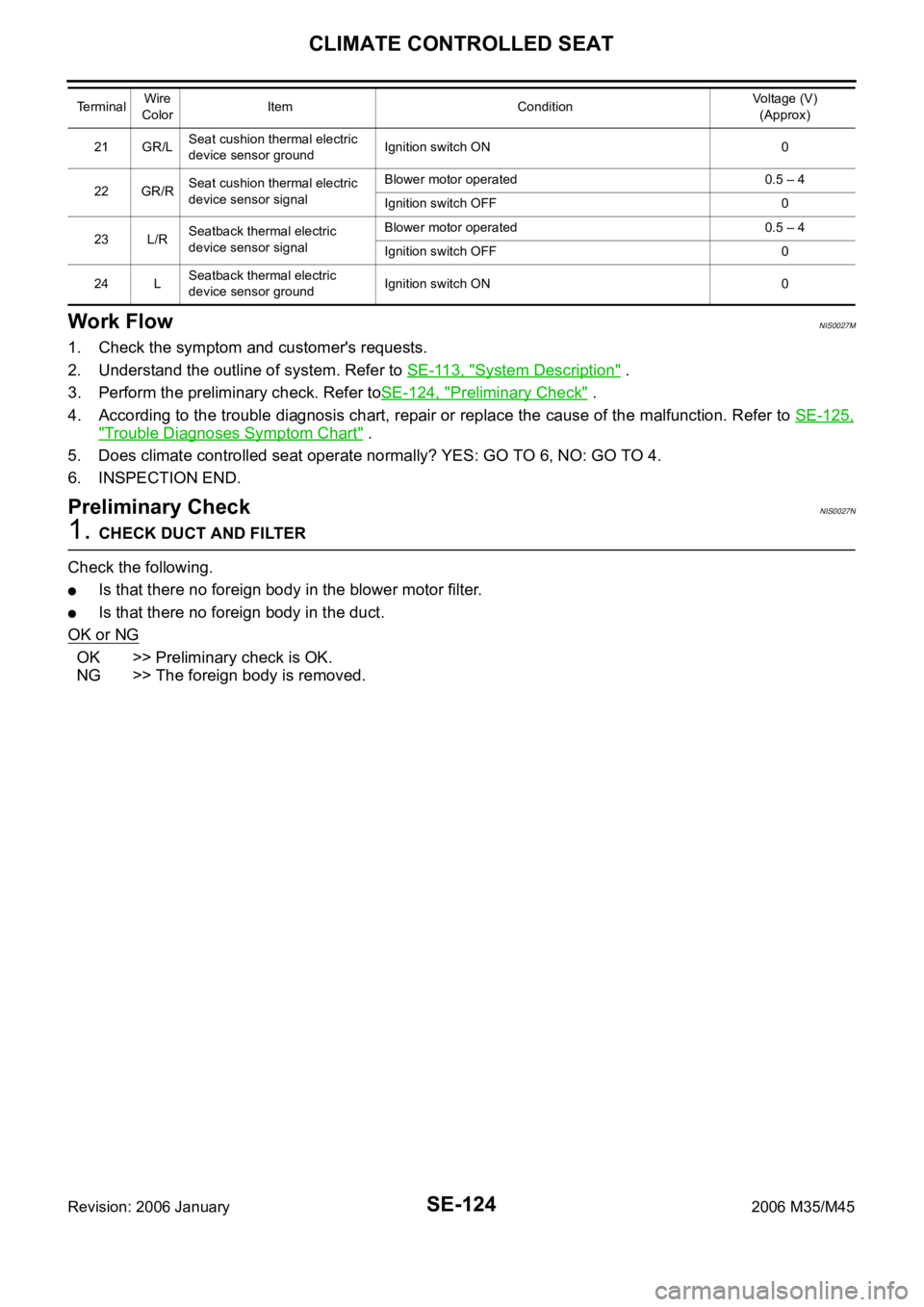
21 GR/LSeat cushion thermal electric
device sensor groundIgnition switch ON 0
22 GR/RSeat cushion thermal electric
device sensor signalBlower motor operated 0.5 – 4
Ignition switch OFF 0
23 L/RSeatback thermal electric
device sensor signalBlower motor operated 0.5 – 4
Ignition switch OFF 0
24 LSeatback thermal electric
device sensor groundIgnition switch ON 0 TerminalWire
ColorItem ConditionVoltage (V)
(Approx)
Page 5325 of 5621

SE-144
HEATED SEAT
Revision: 2006 January2006 M35/M45
When rear heated seat switch (LH, RH) is LOW position, ground is suppled
to rear seat control unit terminal 18,
through rear heated seat switch terminal 2,
through rear heated seat switch terminal 3,
through body grounds B5, B40 and B131
Then rear seat control unit recognizes that rear heated seat switch is LOW position.
When rear heated seat switch is LOW position, power is supplied
through rear seat control unit terminal 6,
through rear seat cushion heater terminal 2,
through rear seat cushion heater terminal 3,
to rear seatback heater terminal 1.
Then ground is suppled
to rear seatback heater terminal 2.
through body grounds B5, B40 and B131.
With power and ground supplied, rear heated seat is operated.
When rear heated seat switch is in LOW position, ground is supplied
to rear heated seat switch terminal 5,
through rear seat control unit terminal 14,
through rear seat control unit terminal 13,
through body grounds B5, B40 and B131.
With power and ground supplied, rear heated seat switch LOW position indicator is illuminated
When rear heated seat switch (LH, RH) is in HIGH position, ground is suppled
to rear seat control unit terminal 17,
through rear heated seat switch terminal 1,
through rear heated seat switch terminal 3,
through body grounds B5, B40 and B131
Then rear seat control unit recognizes that rear heated seat switch is in HIGH position.
When rear heated seat switch is in HIGH position, power is supplied
through rear seat control unit terminal 5,
through rear seat cushion heater terminal 1,
through rear seat cushion heater terminal 3,
to rear seatback heater terminal 1.
Then ground is suppled
to rear seatback heater terminal 2.
through body grounds B5, B40 and B131.
to rear seat cushion heater terminal 2,
through rear seat control unit terminal 6,
through rear seat control unit terminal 8,
through body grounds B5, B40 and B131.
With power and ground supplied, rear heated seat generates heat more than the time of LOW position.
When rear heated seat switch is in HIGH position, ground is supplied
to rear heated seat switch terminal 4,
through rear seat control unit terminal 9,
through rear seat control unit terminal 13,
through body grounds B5, B40 and B131.
With power and ground supplied rear heated seat switch HIGH position indicator is illuminated.
Page 5349 of 5621

SE-168
FRONT SEAT
Revision: 2006 January2006 M35/M45
Disassembly and AssemblyNIS0028H
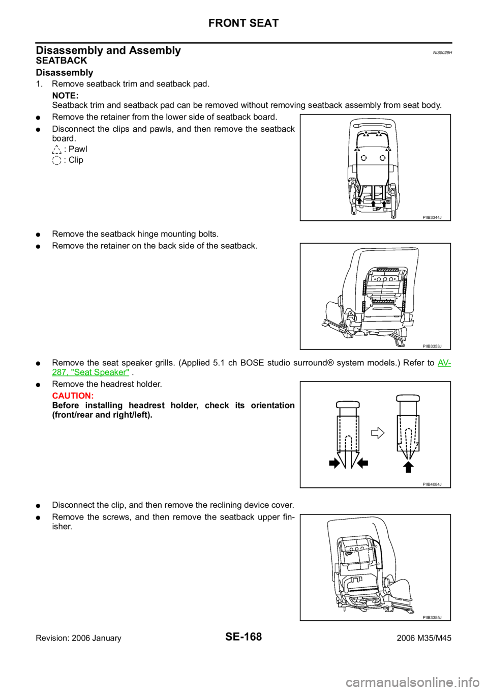
SEATBACK
Disassembly
1. Remove seatback trim and seatback pad.
NOTE:
Seatback trim and seatback pad can be removed without removing seatback assembly from seat body.
Remove the retainer from the lower side of seatback board.
Disconnect the clips and pawls, and then remove the seatback
board.
: Pawl
: Clip
Remove the seatback hinge mounting bolts.
Remove the retainer on the back side of the seatback.
Remove the seat speaker grills. (Applied 5.1 ch BOSE studio surround® system models.) Refer to AV-
287, "Seat Speaker" .
Remove the headrest holder.
CAUTION:
Before installing headrest holder, check its orientation
(front/rear and right/left).
Disconnect the clip, and then remove the reclining device cover.
Remove the screws, and then remove the seatback upper fin-
isher.
PIIB3344J
PIIB3353J
PIIB4084J
PIIB3355J
Page 5424 of 5621
![INFINITI M35 2006 Factory Service Manual TROUBLE DIAGNOSIS
STC-9
[EPS]
C
D
E
F
H
I
J
K
L
MA
B
STC
Revision: 2006 January2006 M35/M45
For Fast and Accurate Trouble DiagnosisNGS000E1
Check the following items with the vehicle stopped
Is air pr INFINITI M35 2006 Factory Service Manual TROUBLE DIAGNOSIS
STC-9
[EPS]
C
D
E
F
H
I
J
K
L
MA
B
STC
Revision: 2006 January2006 M35/M45
For Fast and Accurate Trouble DiagnosisNGS000E1
Check the following items with the vehicle stopped
Is air pr](/manual-img/42/57023/w960_57023-5423.png)
TROUBLE DIAGNOSIS
STC-9
[EPS]
C
D
E
F
H
I
J
K
L
MA
B
STC
Revision: 2006 January2006 M35/M45
For Fast and Accurate Trouble DiagnosisNGS000E1
Check the following items with the vehicle stopped
Is air pressure and size of tires proper?
Is the specified part used for the steering wheel?
Is control unit a genuine part?
Are there any fluid leakage from steering gear assembly, power steering oil pump, and hydraulic pipes,
etc? Refer to PS-8, "
POWER STEERING FLUID" .
Is the fluid level proper? Refer to PS-8, "POWER STEERING FLUID" .
Is the wheel alignment adjusted properly? Refer to FSU-19, "SERVICE DATA AND SPECIFICATIONS
(SDS)" (2WD), FSU-36, "SERVICE DATA AND SPECIFICATIONS (SDS)" (AWD).
Are there any damage or modification to suspension or body resulting in increased weight or altered
ground clearance?
Check each link installation condition of suspension and axle.
Check each connector connection condition.
Check the following items while driving the vehicle
Check conditions when the malfunction occurred (5W 1H).
Is the engine condition normal?
Basic InspectionNGS000E2
POWER SUPPLY CIRCUIT TERMINAL LOOSENESS AND BATTERY
Check battery terminals for looseness on both positive and negative ones and ground connection. Also make
sure that battery voltage does not drop.
Inspection: Power Steering Control Unit Power Supply Circuit and GroundNGS000E3
1. CHECK POWER STEERING CONTROL UNIT CONNECTOR
Turn ignition switch OFF, disconnect power steering control unit harness connector, and check terminal for
deformation, disconnection, looseness, etc.
OK or NG
OK >> GO TO 2.
NG >> Connector terminal connection is loose, damaged, open, or shorted. Repair or replace the termi-
nal.
2. CHECK POWER STEERING CONTROL UNIT GROUND CIRCUIT
Disconnect power steering control unit harness connector M8, and
then check continuity between power steering control unit harness
connector M8 and ground.
OK or NG
OK >> GO TO 3.
NG >> Ground circuit open or shorted. Repair or replace any
inoperative parts. Terminal 2 – Ground : Continuity exist.
SGIA1231E
Page 5447 of 5621
![INFINITI M35 2006 Factory Service Manual STC-32
[RAS]
TROUBLE DIAGNOSIS
Revision: 2006 January2006 M35/M45
For Fast and Accurate Trouble DiagnosisNGS000EN
Check the following items with the vehicle stopped
Is air pressure and size of tires p INFINITI M35 2006 Factory Service Manual STC-32
[RAS]
TROUBLE DIAGNOSIS
Revision: 2006 January2006 M35/M45
For Fast and Accurate Trouble DiagnosisNGS000EN
Check the following items with the vehicle stopped
Is air pressure and size of tires p](/manual-img/42/57023/w960_57023-5446.png)
STC-32
[RAS]
TROUBLE DIAGNOSIS
Revision: 2006 January2006 M35/M45
For Fast and Accurate Trouble DiagnosisNGS000EN
Check the following items with the vehicle stopped
Is air pressure and size of tires proper?
Is the specified part used for the steering wheel?
Is control unit a genuine part?
Are there any fluid leakage from steering gear assembly, power steering oil pump, and hydraulic pipes,
etc? Refer to PS-8, "
POWER STEERING FLUID" .
Is the fluid level proper? Refer to PS-8, "POWER STEERING FLUID" .
Is the wheel alignment is adjusted properly? Refer to FSU-19, "SERVICE DATA AND SPECIFICATIONS
(SDS)" (2WD), FSU-36, "SERVICE DATA AND SPECIFICATIONS (SDS)" (AWD).
Are there any damage or modification to suspension or body resulting in increased weight or altered
ground clearance?
Check each link installation condition of suspension and axle.
Is the battery voltage proper?
Check each connector connection condition.
Check the following items while driving the vehicle
Conditions when the error occurred (5W 1H).
Is the engine is normal?
Basic InspectionNGS000EO
BASIC INSPECTION 1: POWER SUPPLY CIRCUIT TERMINAL LOOSENESS AND BATTERY
Check battery terminals for looseness on both positive and negative ones and ground connection. Also make
sure that battery voltage does not drop.
BASIC INSPECTION 2: RAS WARNING LAMP INSPECTION
1. Make sure RAS warning lamp turns on when ignition switch is turned ON.
If it does not turn on, refer to STC-33, "Trouble Diagnosis Chart" .
2. Make sure that RAS warning lamp turns off when the engine is started after ignition switch is turned ON. If
it does not turn off, perform self-diagnosis. Refer to STC-28, "
SELF-DIAG RESULT MODE" .
3. Always erase DTC memory after completing self-diagnosis. Refer to STC-29, "
How to Erase Self-Diag-
nostic Results" .
BASIC INSPECTION 3: RAS CONTROL UNIT POWER SUPPLY CIRCUIT AND GROUND CIR-
CUIT INSPECTION
1. CHECK RAS CONTROL UNIT CONNECTOR
Turn ignition switch OFF, disconnect RAS control unit harness connector, and check terminal for deformation,
disconnection, looseness, etc.
OK or NG
OK >> GO TO 2.
NG >> Poor connection of connector terminal. Repair or replace the terminal.
2. CHECK RAS CONTROL UNIT GROUND CIRCUIT
1. Disconnect RAS control unit harness connector B127, and then
check continuity between RAS control unit harness connector
B127 and ground.
OK or NG
OK >> GO TO 3.
NG >> Ground circuit open or shorted. Repair or replace any
inoperative parts. Terminal 34 – Ground : Continuity
SGIA1244E
Page 5504 of 5621

AWD CONTROL UNIT
TF-39
C
E
F
G
H
I
J
K
L
MA
B
TF
Revision: 2006 January2006 M35/M45
AWD CONTROL UNITPFP:41650
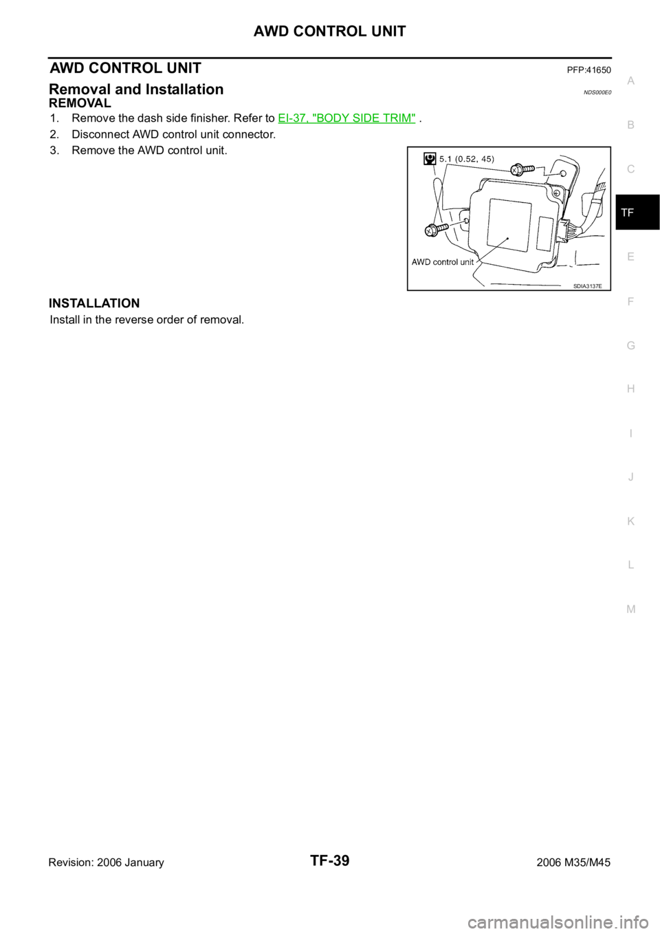
Removal and InstallationNDS000E0
REMOVAL
1. Remove the dash side finisher. Refer to EI-37, "BODY SIDE TRIM" .
2. Disconnect AWD control unit connector.
3. Remove the AWD control unit.
INSTALLATION
Install in the reverse order of removal.
SDIA3137E
Page 5571 of 5621

WW-4
FRONT WIPER AND WASHER SYSTEM
Revision: 2006 January2006 M35/M45
FRONT WIPER AND WASHER SYSTEMPFP:28810
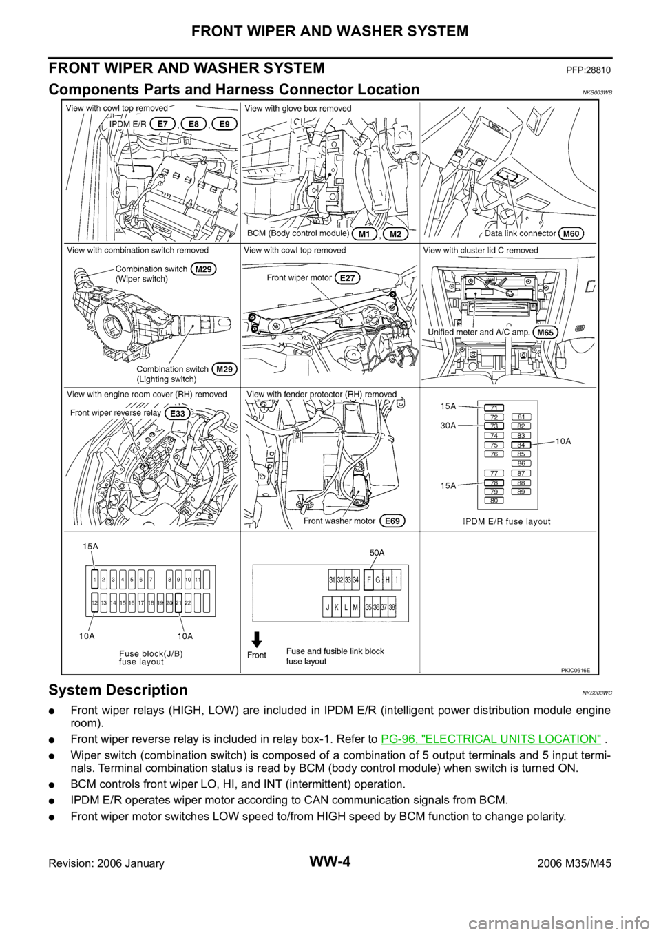
Components Parts and Harness Connector LocationNKS003WB
System DescriptionNKS003WC
Front wiper relays (HIGH, LOW) are included in IPDM E/R (intelligent power distribution module engine
room).
Front wiper reverse relay is included in relay box-1. Refer to PG-96, "ELECTRICAL UNITS LOCATION" .
Wiper switch (combination switch) is composed of a combination of 5 output terminals and 5 input termi-
nals. Terminal combination status is read by BCM (body control module) when switch is turned ON.
BCM controls front wiper LO, HI, and INT (intermittent) operation.
IPDM E/R operates wiper motor according to CAN communication signals from BCM.
Front wiper motor switches LOW speed to/from HIGH speed by BCM function to change polarity.
PKIC0616E