2006 INFINITI M35 Color wire
[x] Cancel search: Color wirePage 3464 of 5621

GI-1
GENERAL INFORMATION
A GENERAL INFORMATION
CONTENTS
C
D
E
F
G
H
I
J
K
L
MB
GI
SECTION GI
Revision: 2006 January2006 M35/M45
GENERAL INFORMATION
PRECAUTIONS .......................................................... 3
Description ............................................................... 3
Precautions for Supplemental Restraint System
(SRS) “AIR BAG” and “SEAT BELT PRE-TEN-
SIONER” .................................................................. 3
Precautions for NVIS/IVIS (NISSAN/INFINITI
VEHICLE IMMOBILIZER SYSTEM - NATS) (If
Equipped) ................................................................. 3
Precautions Necessary for Steering Wheel Rotation
After Battery Disconnect .......................................... 4
OPERATION PROCEDURE ................................. 4
Precautions for Procedures without Cowl Top Cover ..... 4
General Precautions ................................................ 4
Precautions for Three Way Catalyst ......................... 6
Precautions for Fuel (Unleaded Premium Gasoline
Recommended) ...................................................
..... 6
Precautions for Fuel (Unleaded Premium Gasoline
Required) ................................................................. 6
Precautions for Multiport Fuel Injection System or
Engine Control System ............................................ 7
Precautions for Hoses .............................................. 7
HOSE REMOVAL AND INSTALLATION ............... 7
HOSE CLAMPING ................................................ 7
Precautions for Engine Oils ...................................... 8
HEALTH PROTECTION PRECAUTIONS ............. 8
Precautions for Air Conditioning ............................... 8
HOW TO USE THIS MANUAL ................................... 9
Description ............................................................... 9
Terms ....................................................................... 9
Units ......................................................................... 9
Contents ................................................................... 9
Relation between Illustrations and Descriptions .... 10
Components ............................................................ 11
SYMBOLS ........................................................
.... 11
How to Follow Trouble Diagnoses .......................... 12
DESCRIPTION .................................................... 12
HOW TO FOLLOW TEST GROUPS IN TROU-
BLE DIAGNOSES ............................................... 12
HARNESS WIRE COLOR AND CONNECTOR
NUMBER INDICATION ....................................... 13KEY TO SYMBOLS SIGNIFYING MEASURE-
MENTS OR PROCEDURES ............................... 14
How to Read Wiring Diagrams ............................... 16
CONNECTOR SYMBOLS ................................... 16
SAMPLE/WIRING DIAGRAM - EXAMPL - .......... 17
DESCRIPTION .................................................... 18
Abbreviations .......................................................... 24
SERVICE INFORMATION FOR ELECTRICAL INCI-
DENT ......................................................................... 25
How to Check Terminal ........................................... 25
CONNECTOR AND TERMINAL PIN KIT ............ 25
HOW TO PROBE CONNECTORS ...................... 25
How to Perform Efficient Diagnosis for an Electrical
Incident ................................................................... 28
WORK FLOW ...................................................... 28
INCIDENT SIMULATION TESTS ........................ 28
CIRCUIT INSPECTION ....................................
... 31
Control Units and Electrical Parts ........................... 36
PRECAUTIONS .................................................. 36
CONSULT-II CHECKING SYSTEM .......................... 38
Description .............................................................. 38
Function and System Application ........................... 38
Nickel Metal Hydride Battery Replacement ............ 39
Checking Equipment .............................................. 39
CONSULT-II Start Procedure .................................. 39
CONSULT-II Data Link Connector (DLC) Circuit .... 40
INSPECTION PROCEDURE .............................. 40
CIRCUIT DIAGRAM ............................................ 41
LIFTING POINT ......................................................... 42
Special Service Tools ............................................. 42
Garage Jack and Safety Stand and 2-Pole Lift ....... 42
Board-On Lift .......................................................... 43
TOW TRUCK TOWING ............................................. 44
Tow Truck Towing ................................................... 44
2WD MODELS .................................................... 44
AWD MODELS .................................................... 45
Vehicle Recovery (Freeing a Stuck Vehicle) ........... 45
FRONT ................................................................ 45
REAR .................................................................. 45
AUTOMATIC TRANSMISSION ........................... 46
Page 3476 of 5621
HOW TO USE THIS MANUAL
GI-13
C
D
E
F
G
H
I
J
K
L
MB
GI
Revision: 2006 January2006 M35/M45
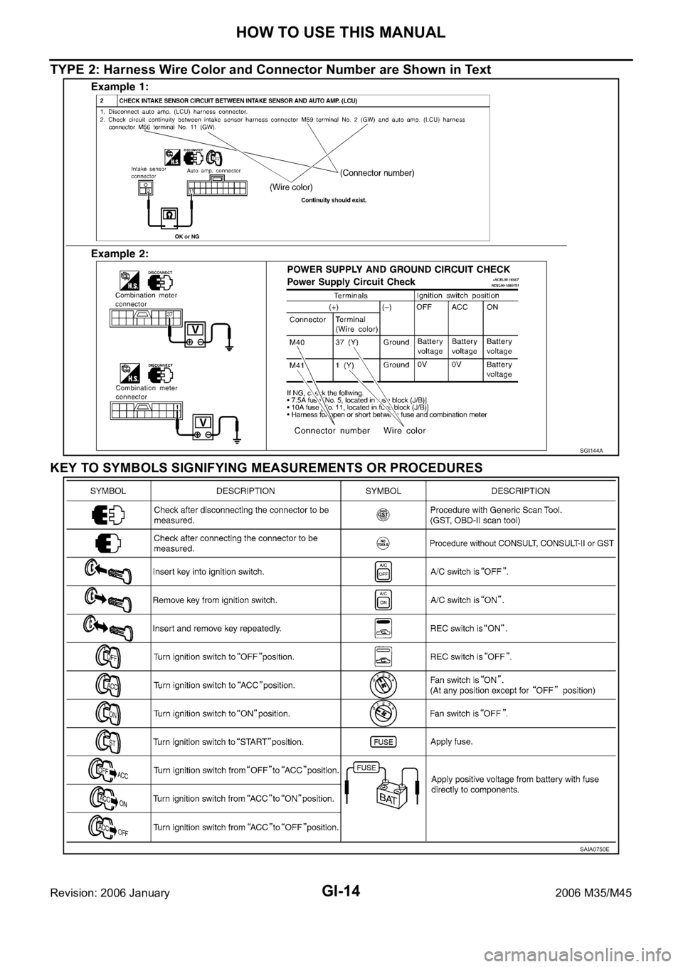
3.Symbol used in illustration
Symbols included in illustrations refer to measurements or procedures. Before diagnosing a problem,
familiarize yourself with each symbol. Refer to "Connector Symbols" in GI Section and "KEY TO SYM-
BOLS SIGNIFYING MEASUREMENTS OR PROCEDURES" below.
4.Action items
Next action for each test group is indicated based on result of each question. Test group number is shown
in the left upper portion of each test group.
HARNESS WIRE COLOR AND CONNECTOR NUMBER INDICATION
There are two types of harness wire color and connector number indication.
TYPE 1: Harness Wire Color and Connector Number are Shown in Illustration
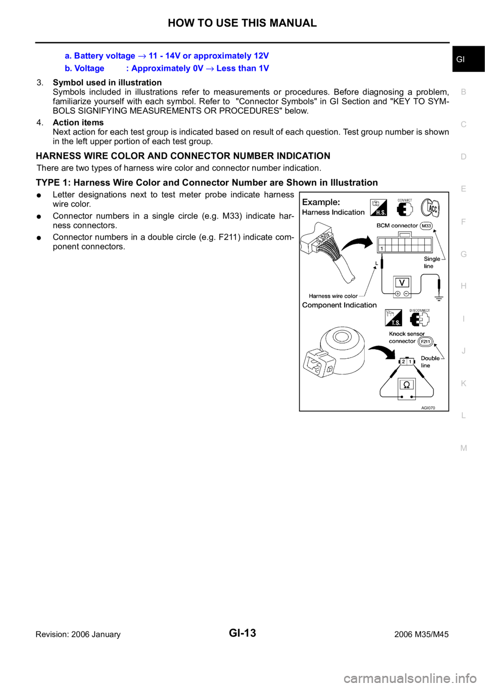
Letter designations next to test meter probe indicate harness
wire color.
Connector numbers in a single circle (e.g. M33) indicate har-
ness connectors.
Connector numbers in a double circle (e.g. F211) indicate com-
ponent connectors.a. Battery voltage
11 - 14V or approximately 12V
b. Voltage : Approximately 0V
Less than 1V
AGI070
Page 3477 of 5621
GI-14
HOW TO USE THIS MANUAL
Revision: 2006 January2006 M35/M45
TYPE 2: Harness Wire Color and Connector Number are Shown in Text
KEY TO SYMBOLS SIGNIFYING MEASUREMENTS OR PROCEDURES
SGI144A
SAIA0750E
Page 3482 of 5621
HOW TO USE THIS MANUAL
GI-19
C
D
E
F
G
H
I
J
K
L
MB
GI
Revision: 2006 January2006 M35/M45
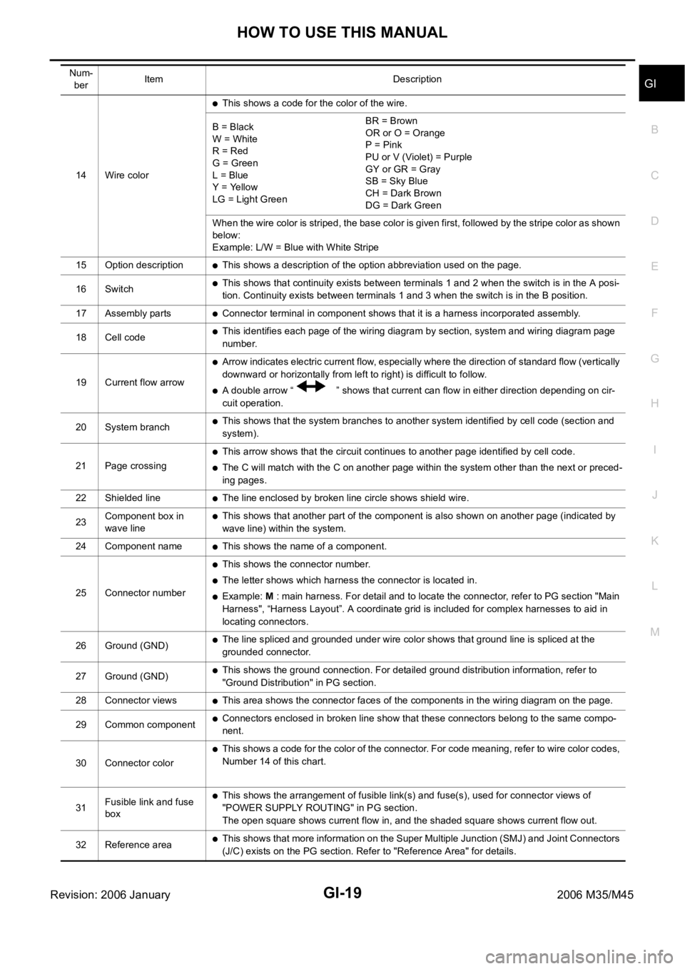
14 Wire color
This shows a code for the color of the wire.
B = Black
W = White
R = Red
G = Green
L = Blue
Y = Yellow
LG = Light GreenBR = Brown
OR or O = Orange
P = Pink
PU or V (Violet) = Purple
GY or GR = Gray
SB = Sky Blue
CH = Dark Brown
DG = Dark Green
When the wire color is striped, the base color is given first, followed by the stripe color as shown
below:
Example: L/W = Blue with White Stripe
15 Option description
This shows a description of the option abbreviation used on the page.
16 Switch
This shows that continuity exists between terminals 1 and 2 when the switch is in the A posi-
tion. Continuity exists between terminals 1 and 3 when the switch is in the B position.
17 Assembly parts
Connector terminal in component shows that it is a harness incorporated assembly.
18 Cell code
This identifies each page of the wiring diagram by section, system and wiring diagram page
number.
19 Current flow arrow
Arrow indicates electric current flow, especially where the direction of standard flow (vertically
downward or horizontally from left to right) is difficult to follow.
A double arrow “ ” shows that current can flow in either direction depending on cir-
cuit operation.
20 System branch
This shows that the system branches to another system identified by cell code (section and
system).
21 Page crossing
This arrow shows that the circuit continues to another page identified by cell code.
The C will match with the C on another page within the system other than the next or preced-
ing pages.
22 Shielded line
The line enclosed by broken line circle shows shield wire.
23Component box in
wave line
This shows that another part of the component is also shown on another page (indicated by
wave line) within the system.
24 Component name
This shows the name of a component.
25 Connector number
This shows the connector number.
The letter shows which harness the connector is located in.
Example: M : main harness. For detail and to locate the connector, refer to PG section "Main
Harness", “Harness Layout”. A coordinate grid is included for complex harnesses to aid in
locating connectors.
26 Ground (GND)
The line spliced and grounded under wire color shows that ground line is spliced at the
grounded connector.
27 Ground (GND)
This shows the ground connection. For detailed ground distribution information, refer to
"Ground Distribution" in PG section.
28 Connector views
This area shows the connector faces of the components in the wiring diagram on the page.
29 Common component
Connectors enclosed in broken line show that these connectors belong to the same compo-
nent.
30 Connector color
This shows a code for the color of the connector. For code meaning, refer to wire color codes,
Number 14 of this chart.
31Fusible link and fuse
box
This shows the arrangement of fusible link(s) and fuse(s), used for connector views of
"POWER SUPPLY ROUTING" in PG section.
The open square shows current flow in, and the shaded square shows current flow out.
32 Reference area
This shows that more information on the Super Multiple Junction (SMJ) and Joint Connectors
(J/C) exists on the PG section. Refer to "Reference Area" for details. Num-
berItem Description
Page 3483 of 5621
GI-20
HOW TO USE THIS MANUAL
Revision: 2006 January2006 M35/M45
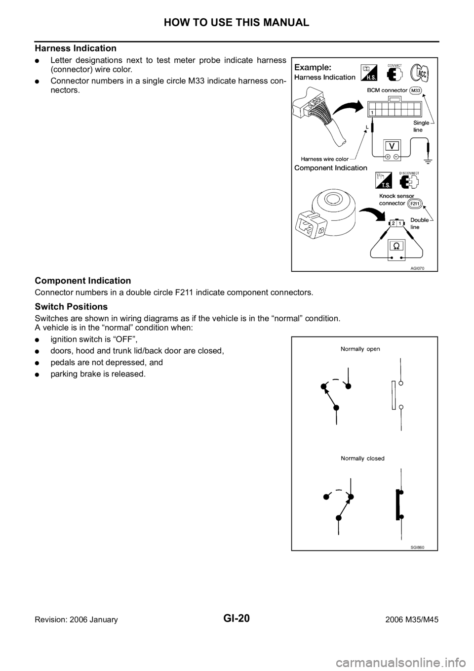
Harness Indication
Letter designations next to test meter probe indicate harness
(connector) wire color.
Connector numbers in a single circle M33 indicate harness con-
nectors.
Component Indication
Connector numbers in a double circle F211 indicate component connectors.
Switch Positions
Switches are shown in wiring diagrams as if the vehicle is in the “normal” condition.
A vehicle is in the “normal” condition when:
ignition switch is “OFF”,
doors, hood and trunk lid/back door are closed,
pedals are not depressed, and
parking brake is released.
AGI070
SGI860
Page 3546 of 5621
![INFINITI M35 2006 Factory Service Manual POWER WINDOW SYSTEM
GW-27
C
D
E
F
G
H
J
K
L
MA
B
GW
Revision: 2006 January2006 M35/M45
Terminal and Reference Value for BCMNIS0021L
Terminal Wire color Item ConditionVoltage [V]
(Approx.)
12 PFront do INFINITI M35 2006 Factory Service Manual POWER WINDOW SYSTEM
GW-27
C
D
E
F
G
H
J
K
L
MA
B
GW
Revision: 2006 January2006 M35/M45
Terminal and Reference Value for BCMNIS0021L
Terminal Wire color Item ConditionVoltage [V]
(Approx.)
12 PFront do](/manual-img/42/57023/w960_57023-3545.png)
POWER WINDOW SYSTEM
GW-27
C
D
E
F
G
H
J
K
L
MA
B
GW
Revision: 2006 January2006 M35/M45
Terminal and Reference Value for BCMNIS0021L
Terminal Wire color Item ConditionVoltage [V]
(Approx.)
12 PFront door switch
passenger side signalON (Open) 0
OFF (Close) Battery voltage
22 G Power window serial link IGN SW ON or power window
timer operating.
38 W Ignition switch (ON or START) Ignition switch
(ON or START position)Battery voltage
39 L CAN - H — —
40 P CAN - L — —
42 P Power source (Fuse) — Battery voltage
52 B Ground — 0
53 BR Rap signalIGN SW ON Battery voltage
Within 45 second after ignition
switch is turned to OFFBattery voltage
When driver side or passenger
side door is opened daring
retained power operation0
54 O Power window power supply — Battery voltage
55 W Power source (Fusible link) — Battery voltage
62 VFront door switch
driver side signalON (Open) 0
OFF (Close) Battery voltage
PIIA2344J
Page 3547 of 5621
![INFINITI M35 2006 Factory Service Manual GW-28
POWER WINDOW SYSTEM
Revision: 2006 January2006 M35/M45
Terminal and Reference Value for Power Window Main SwitchNIS0021M
Terminal Wire color Item ConditionVoltage [V]
(Approx.)
2 W/B Encoder gro INFINITI M35 2006 Factory Service Manual GW-28
POWER WINDOW SYSTEM
Revision: 2006 January2006 M35/M45
Terminal and Reference Value for Power Window Main SwitchNIS0021M
Terminal Wire color Item ConditionVoltage [V]
(Approx.)
2 W/B Encoder gro](/manual-img/42/57023/w960_57023-3546.png)
GW-28
POWER WINDOW SYSTEM
Revision: 2006 January2006 M35/M45
Terminal and Reference Value for Power Window Main SwitchNIS0021M
Terminal Wire color Item ConditionVoltage [V]
(Approx.)
2 W/B Encoder ground — 0
4BRDoor key cylinder switch
LOCK signalKey position
(Neutral
Locked)5 0
6V/RDoor key cylinder switch
UNLOCK signalKey position
(Neutral
Unlocked)5 0
8LFront driver side power window
motor UP signalWhen front LH switch in
power window main switch is
UP at operated. Battery voltage
9 G/W Encoder pulse signal 2When power window motor oper-
ates.
10 Y/B Rap signalIGN SW ON Battery voltage
Within 45 second after ignition
switch is turned to OFFBattery voltage
When driver side or passenger
side door is opened daring
retained power operation0
11 GFront driver side power window
motor DOWN signalWhen front LH switch in
power window main switch is
DOWN at operated. Battery voltage
13 G/Y Encoder pulse signal 1When power window motor oper-
ates.
14 Y Power window serial linkIGN SW ON or power window
timer operating.
15 G/R Encoder power supplyWhen ignition switch ON or power
window timer operates.10
17 B Ground — 0
19 W/B Battery power supply — Battery voltage
OCC3383D
OCC3383D
PIIA2344J
Page 3548 of 5621
POWER WINDOW SYSTEM
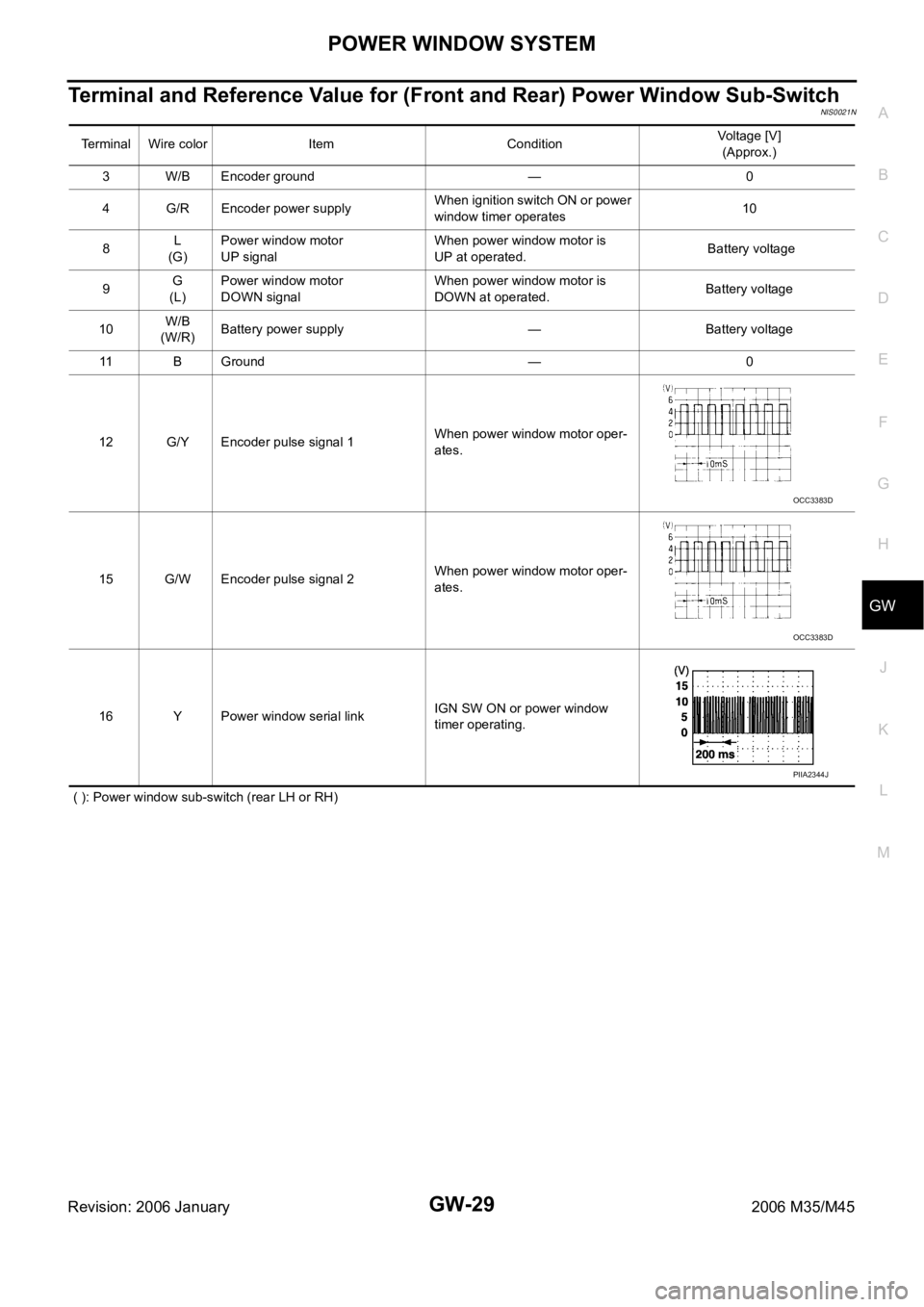
GW-29
C
D
E
F
G
H
J
K
L
MA
B
GW
Revision: 2006 January2006 M35/M45
Terminal and Reference Value for (Front and Rear) Power Window Sub-SwitchNIS0021N
( ): Power window sub-switch (rear LH or RH)Terminal Wire color Item ConditionVoltage [V]
(Approx.)
3 W/B Encoder ground — 0
4 G/R Encoder power supplyWhen ignition switch ON or power
window timer operates10
8L
(G)Power window motor
UP signalWhen power window motor is
UP at operated. Battery voltage
9G
(L)Power window motor
DOWN signalWhen power window motor is
DOWN at operated.Battery voltage
10W/B
(W/R)Battery power supply — Battery voltage
11 B G r o u n d — 0
12 G/Y Encoder pulse signal 1When power window motor oper-
ates.
15 G/W Encoder pulse signal 2When power window motor oper-
ates.
16 Y Power window serial linkIGN SW ON or power window
timer operating.
OCC3383D
OCC3383D
PIIA2344J