2006 INFINITI M35 Color wire
[x] Cancel search: Color wirePage 4482 of 5621
HEADLAMP (FOR USA) - XENON TYPE -
LT-55
C
D
E
F
G
H
I
J
L
MA
B
LT
Revision: 2006 January2006 M35/M45
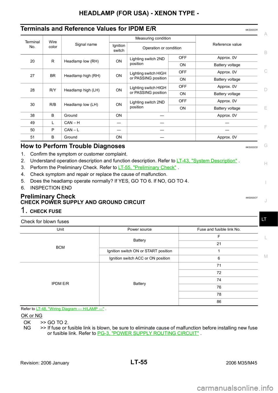
Terminals and Reference Values for IPDM E/RNKS003OR
How to Perform Trouble DiagnosesNKS003OS
1. Confirm the symptom or customer complaint.
2. Understand operation description and function description. Refer to LT- 4 3 , "
System Description" .
3. Perform the Preliminary Check. Refer to LT-55, "
Preliminary Check" .
4. Check symptom and repair or replace the cause of malfunction.
5. Does the headlamp operate normally? If YES, GO TO 6. If NO, GO TO 4.
6. INSPECTION END
Preliminary CheckNKS003OT
CHECK POWER SUPPLY AND GROUND CIRCUIT
1. CHECK FUSE
Check for blown fuses
Refer to LT-48, "Wiring Diagram — H/LAMP —" .
OK or NG
OK >> GO TO 2.
NG >> If fuse or fusible link is blown, be sure to eliminate cause of malfunction before installing new fuse
or fusible link. Refer to PG-3, "
POWER SUPPLY ROUTING CIRCUIT" .
Terminal
No.Wire
colorSignal nameMeasuring condition
Reference value
Ignition
switchOperation or condition
20 R Headlamp low (RH) ONLighting switch 2ND
positionOFF Approx. 0V
ON Battery voltage
27 BR Headlamp high (RH) ONLighting switch HIGH
or PASSING positionOFF Approx. 0V
ON Battery voltage
28 R/Y Headlamp high (LH) ONLighting switch HIGH
or PASSING positionOFF Approx. 0V
ON Battery voltage
30 R/B Headlamp low (LH) ONLighting switch 2ND
positionOFF Approx. 0V
ON Battery voltage
38 B Ground ON — Approx. 0V
49 L CAN
H — — —
50 P CAN
L — — —
51 B Ground ON — Approx. 0V
Unit Power source Fuse and fusible link No.
BCMBatteryF
21
Ignition switch ON or START position 1
Ignition switch ACC or ON position 6
IPDM E/R Battery71
72
74
76
78
86
Page 4500 of 5621

HEADLAMP (FOR USA) - XENON TYPE -
LT-73
C
D
E
F
G
H
I
J
L
MA
B
LT
Revision: 2006 January2006 M35/M45
General Information for Xenon Headlamp Trouble DiagnosisNKS003P2
In most cases, malfunction of xenon headlamp - "does not illuminate", "flickers" or "dark" - is caused by a mal-
functioning xenon bulb. A HID control unit or lamp housing, however, may be a cause of malfunction. Be sure
to perform trouble diagnosis following the steps described below.
Caution:NKS003P3
Installation or removal of connector must be done with lighting switch OFF.
Disconnect the battery cable from the negative terminal or remove power fuse.
When the lamp is illuminated (when lighting switch is ON), never touch harness, HID control unit, inside of
lamp, or lamp metal parts.
To check illumination, temporarily install lamp in vehicle. Be sure to connect power at vehicle side connec-
tor.
If error can be traced directly to electrical system, first check for items such as blown fuses and fusible
links, broken wires or loose connectors, dislocated terminals, and improper connections.
Never work with wet hands.
Using a tester for HID control unit circuit trouble diagnosis is prohibited.
Disassembling HID control unit or harnesses (bulb socket harness, ECM harness) is prohibited.
Immediately after illumination, light intensity and color will fluctuate, but there is nothing wrong.
When bulb has come to end of its life, brightness will drop significantly, it will flash repeatedly, or light color
will turn reddish.
Xenon Headlamp Trouble DiagnosisNKS003P4
1. CHECK 1: XENON HEADLAMP LIGHTING
Install normal xenon bulb to corresponding xenon bulb headlamp, and check if lamp lights up.
OK or NG
OK >> Replace xenon bulb.
NG >> GO TO 2.
2. CHECK 2: XENON HEADLAMP LIGHTING
Install normal HID control unit to corresponding xenon headlamp, and check if lamp lights up.
OK or NG
OK >> Replace HID control unit.
NG >> GO TO 3.
3. CHECK 3: XENON HEADLAMP LIGHTING
Install normal xenon lamp housing assembly to corresponding xenon headlamp, and check if lamp lights up.
OK or NG
OK >> Replace xenon headlamp housing assembly. [Malfunction in starter (boosting circuit) in xenon
headlamp housing]
NG >> INSPECTION END
Page 4516 of 5621
HEADLAMP (FOR CANADA) - DAYTIME LIGHT SYSTEM -
LT-89
C
D
E
F
G
H
I
J
L
MA
B
LT
Revision: 2006 January2006 M35/M45
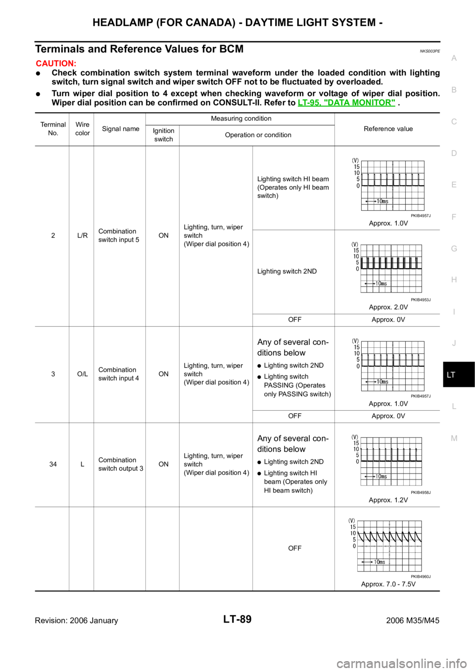
Terminals and Reference Values for BCMNKS003PE
CAUTION:
Check combination switch system terminal waveform under the loaded condition with lighting
switch, turn signal switch and wiper switch OFF not to be fluctuated by overloaded.
Turn wiper dial position to 4 except when checking waveform or voltage of wiper dial position.
Wiper dial position can be confirmed on CONSULT-II. Refer to LT- 9 5 , "
DATA MONITOR" .
Terminal
No.Wire
colorSignal nameMeasuring condition
Reference value
Ignition
switchOperation or condition
2L/RCombination
switch input 5ONLighting, turn, wiper
switch
(Wiper dial position 4)Lighting switch HI beam
(Operates only HI beam
switch)
Approx. 1.0V
Lighting switch 2ND
Approx. 2.0V
OFF Approx. 0V
3O/LCombination
switch input 4ONLighting, turn, wiper
switch
(Wiper dial position 4)
Any of several con-
ditions below
Lighting switch 2ND
Lighting switch
PASSING (Operates
only PASSING switch)
Approx. 1.0V
OFF Approx. 0V
34 LCombination
switch output 3ONLighting, turn, wiper
switch
(Wiper dial position 4)
Any of several con-
ditions below
Lighting switch 2ND
Lighting switch HI
beam (Operates only
HI beam switch)
Approx. 1.2V
OFF
Approx. 7.0 - 7.5V
PKIB4957J
PKIB4953J
PKIB4957J
PKIB4958J
PKIB4960J
Page 4517 of 5621
LT-90
HEADLAMP (FOR CANADA) - DAYTIME LIGHT SYSTEM -
Revision: 2006 January2006 M35/M45
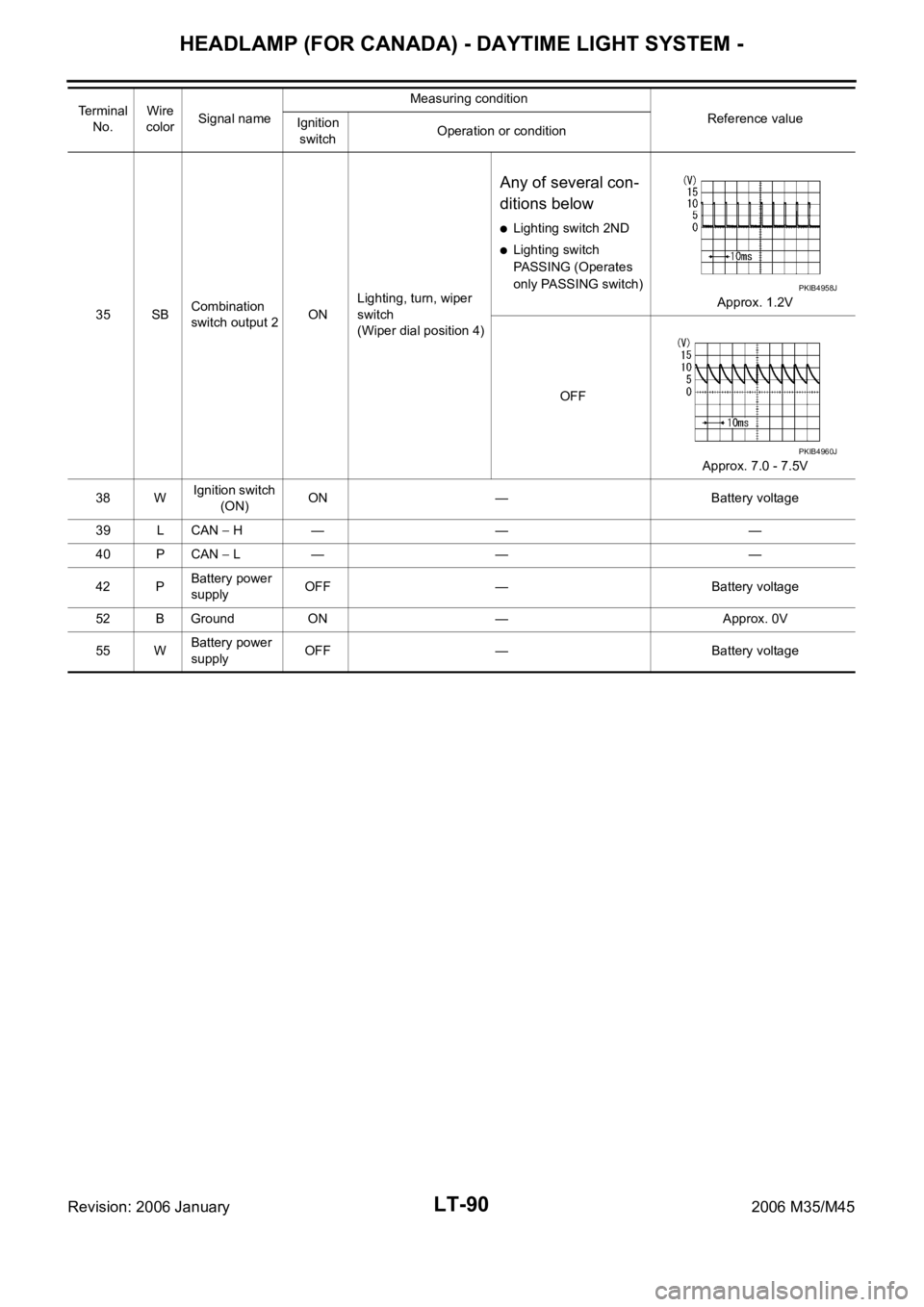
35 SBCombination
switch output 2ONLighting, turn, wiper
switch
(Wiper dial position 4)
Any of several con-
ditions below
Lighting switch 2ND
Lighting switch
PASSING (Operates
only PASSING switch)
Approx. 1.2V
OFF
Approx. 7.0 - 7.5V
38 WIgnition switch
(ON) ON — Battery voltage
39 L CAN
H — — —
40 P CAN
L — — —
42 PBattery power
supplyOFF — Battery voltage
52 B Ground ON — Approx. 0V
55 WBattery power
supplyOFF — Battery voltage Terminal
No.Wire
colorSignal nameMeasuring condition
Reference value
Ignition
switchOperation or condition
PKIB4958J
PKIB4960J
Page 4518 of 5621

HEADLAMP (FOR CANADA) - DAYTIME LIGHT SYSTEM -
LT-91
C
D
E
F
G
H
I
J
L
MA
B
LT
Revision: 2006 January2006 M35/M45
Terminals and Reference Values for IPDM E/RNKS003PF
NOTE:
Daytime running light is operating: Lighting switch in OFF position with engine running and parking brake is released.
How to Perform Trouble DiagnosisNKS003PG
1. Confirm the symptom or customer complaint.
2. Understand operation description and function description. Refer to LT- 7 9 , "
System Description" .
3. Perform the Preliminary Check. Refer to LT-92, "
Preliminary Check" .
4. Check symptom and repair or replace the cause of malfunction.
5. Does the headlamp operate normally? If YES: GO TO 6. If NO: GO TO 4.
6. INSPECTION END
Terminal
No.Wire
colorSignal nameMeasuring condition
Reference value
Ignition
switchOperation or condition
20 R Headlamp low (RH) ON Lighting switch 2ND positionOFF Approx. 0V
ON Battery voltage
27 BR Headlamp high (RH) ONLighting switch HIGH or PASSING
positionOFF Approx. 0V
ON Battery voltage
Daytime running light is operating
NOTEApprox. 6.5V
28 R/Y Headlamp high (LH) ONLighting switch HIGH or PASSING
positionOFF Approx. 0V
ON Battery voltage
Daytime running light is operating
NOTEApprox. 6.5V
30 R/B Headlamp low (LH) ON Lighting switch 2ND positionOFF Approx. 0V
ON Battery voltage
38 B Ground ON — Approx. 0V
49 L CAN
H — — —
50 P CAN
L — — —
51 B Ground ON — Approx. 0V
58 SBDaytime light relay
signalONDaytime running light is operating
NOTEApprox. 0V
Daytime running light is not operating Battery voltage
Page 4542 of 5621

HEADLAMP (FOR CANADA) - DAYTIME LIGHT SYSTEM -
LT-115
C
D
E
F
G
H
I
J
L
MA
B
LT
Revision: 2006 January2006 M35/M45
General Information for Xenon Headlamp Trouble DiagnosisNKS003PR
In most cases, malfunction of xenon headlamp - "does not illuminate", "flickers" or "dark" - is caused by a mal-
functioning xenon bulb. A HID control unit or lamp housing, however, may be a cause of malfunction. Be sure
to perform trouble diagnosis following the steps described below.
CAUTION:NKS003PS
Installation or removal of connector must be done with lighting switch OFF.
When lamp is illuminated (when lighting switch is ON), do not touch harness, HID control unit, inside of
lamp, or lamp metal parts.
To check illumination, temporarily install lamp in the vehicle. Be sure to connect power at the vehicle-side
connector.
If the error can be traced directly to the electrical system, first check for items such as burned-out fuses
and fusible links, broken wires or loose connectors, pulled-out terminals, and improper connections.
Do not work with wet hands.
Using a tester for HID control unit circuit trouble diagnosis is prohibited.
Disassembling the HID control unit or harnesses (bulb socket harness, ECM harness) is prohibited.
Immediately after illumination, the light intensity and color will fluctuate, but there is nothing wrong.
When the bulb has reached the end of its lifetime, the brightness may drop significantly, it may flash
repeatedly, or the light may turn a reddish color.
Xenon Headlamp Trouble DiagnosisNKS003PT
1. CHECK 1: XENON HEADLAMP LIGHTING
Install normal xenon bulb to corresponding xenon bulb headlamp, and check if lamp lights up.
OK or NG
OK >> Replace xenon bulb.
NG >> GO TO 2.
2. CHECK 2: XENON HEADLAMP LIGHTING
Install normal HID control unit to corresponding xenon headlamp, and check if lamp lights up.
OK or NG
OK >> Replace HID control unit.
NG >> GO TO 3.
3. CHECK 3: XENON HEADLAMP LIGHTING
Install normal xenon lamp housing assembly to corresponding xenon headlamp, and check if lamp lights up.
OK or NG
OK >> Replace xenon headlamp housing assembly. [Malfunction in starter (boosting circuit) in xenon
headlamp housing]
NG >> INSPECTION END
Aiming AdjustmentNKS003PU
Refer to LT- 7 4 , "Aiming Adjustment" .
Bulb ReplacementNKS003PV
Refer to LT- 7 5 , "Bulb Replacement" .
Removal and InstallationNKS003PW
Refer to LT- 4 1 , "Removal and Installation" .
Disassembly and AssemblyNKS003PX
Refer to LT- 7 7 , "Disassembly and Assembly" .
Page 4550 of 5621
AUTO LIGHT SYSTEM
LT-123
C
D
E
F
G
H
I
J
L
MA
B
LT
Revision: 2006 January2006 M35/M45
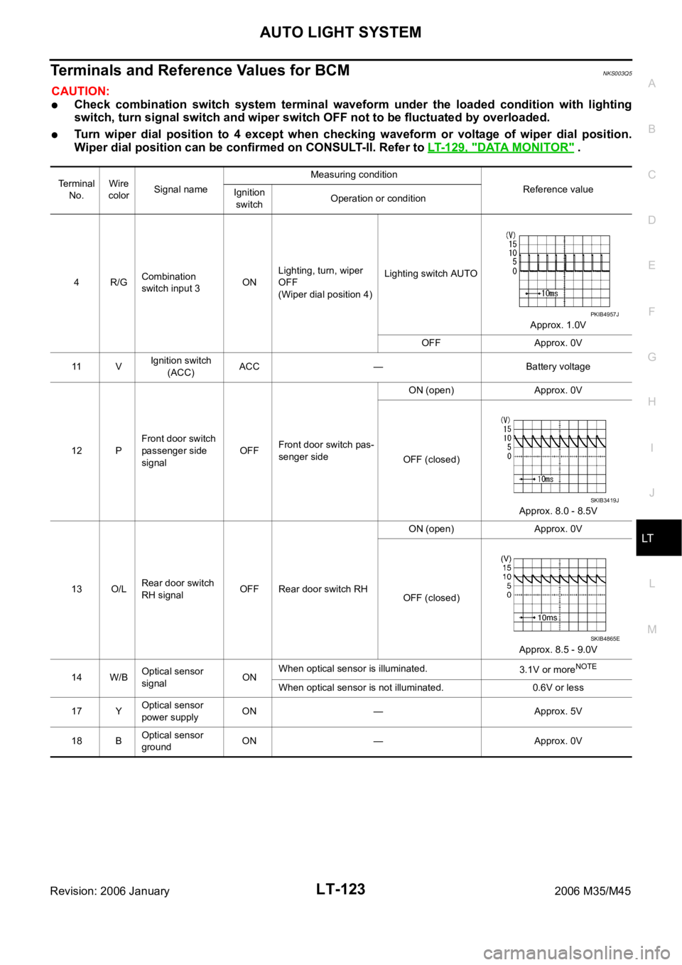
Terminals and Reference Values for BCMNKS003Q5
CAUTION:
Check combination switch system terminal waveform under the loaded condition with lighting
switch, turn signal switch and wiper switch OFF not to be fluctuated by overloaded.
Turn wiper dial position to 4 except when checking waveform or voltage of wiper dial position.
Wiper dial position can be confirmed on CONSULT-II. Refer to LT-129, "
DATA MONITOR" .
Terminal
No.Wire
colorSignal nameMeasuring condition
Reference value
Ignition
switchOperation or condition
4R/GCombination
switch input 3ONLighting, turn, wiper
OFF
(Wiper dial position 4)Lighting switch AUTO
Approx. 1.0V
OFF Approx. 0V
11 VIgnition switch
(ACC)ACC — Battery voltage
12 PFront door switch
passenger side
signalOFFFront door switch pas-
senger sideON (open) Approx. 0V
OFF (closed)
Approx. 8.0 - 8.5V
13 O/LRear door switch
RH signalOFF Rear door switch RHON (open) Approx. 0V
OFF (closed)
Approx. 8.5 - 9.0V
14 W/BOptical sensor
signalONWhen optical sensor is illuminated.
3.1V or more
NOTE
When optical sensor is not illuminated. 0.6V or less
17 YOptical sensor
power supplyON — Approx. 5V
18 BOptical sensor
groundON — Approx. 0V
PKIB4957J
SKIB3419J
SKIB4865E
Page 4551 of 5621
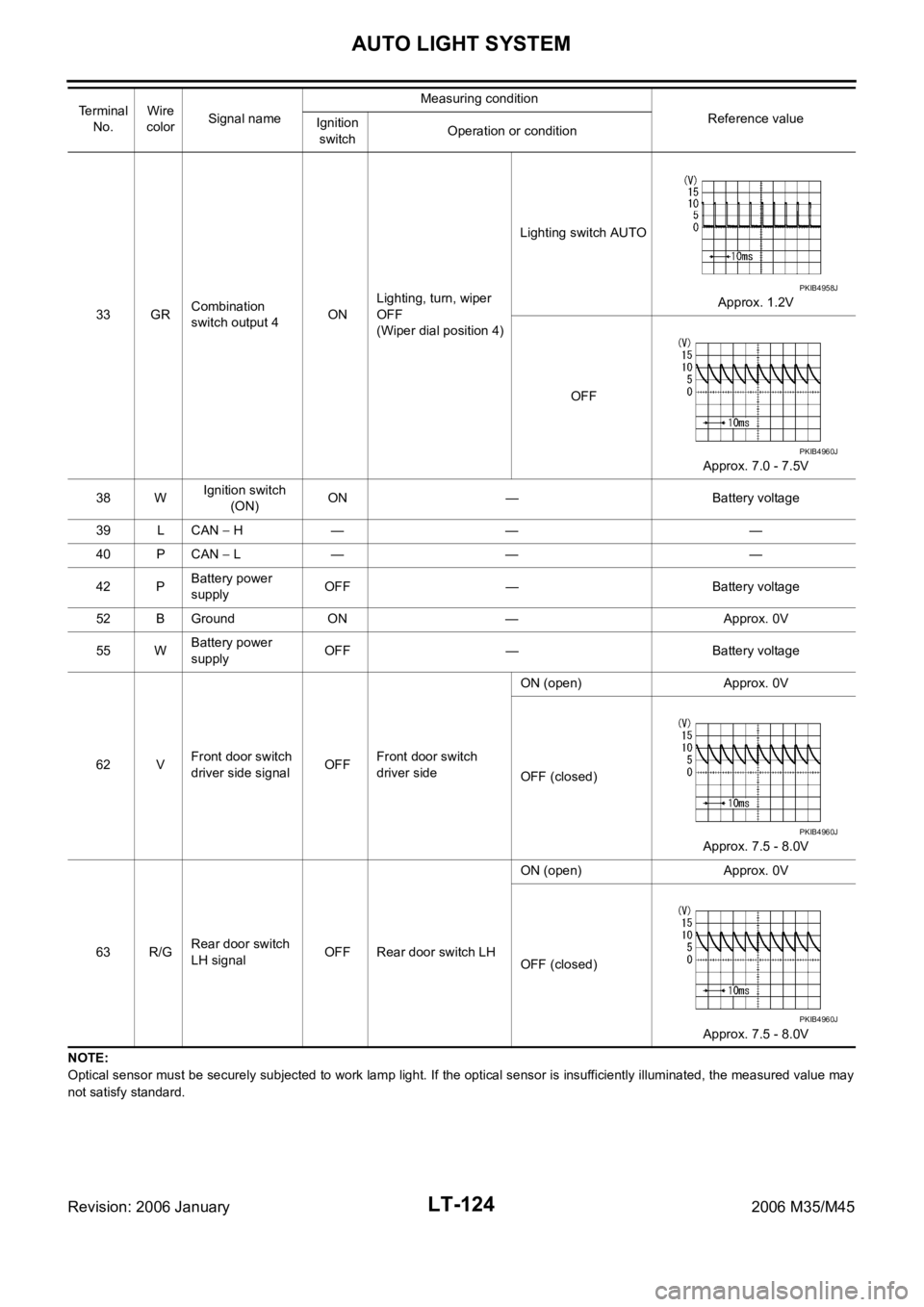
LT-124
AUTO LIGHT SYSTEM
Revision: 2006 January2006 M35/M45
NOTE:
Optical sensor must be securely subjected to work lamp light. If the optical sensor is insufficiently illuminated, the measured value may
not satisfy standard.33 GRCombination
switch output 4ONLighting, turn, wiper
OFF
(Wiper dial position 4)Lighting switch AUTO
Approx. 1.2V
OFF
Approx. 7.0 - 7.5V
38 WIgnition switch
(ON) ON — Battery voltage
39 L CAN
H — — —
40 P CAN
L — — —
42 PBattery power
supplyOFF — Battery voltage
52 B Ground ON — Approx. 0V
55 WBattery power
supplyOFF — Battery voltage
62 VFront door switch
driver side signalOFFFront door switch
driver sideON (open) Approx. 0V
OFF (closed)
Approx. 7.5 - 8.0V
63 R/GRear door switch
LH signalOFF Rear door switch LHON (open) Approx. 0V
OFF (closed)
Approx. 7.5 - 8.0V Te r m i n a l
No.Wire
colorSignal nameMeasuring condition
Reference value
Ignition
switchOperation or condition
PKIB4958J
PKIB4960J
PKIB4960J
PKIB4960J