Page 3600 of 5621
REAR WINDOW DEFOGGER
GW-81
C
D
E
F
G
H
J
K
L
MA
B
GW
Revision: 2006 January2006 M35/M45
Terminal and Reference Value for BCMNIS0022M
Terminal and Reference Value for IPDM E/RNIS0022N
Terminal Wire color Item ConditionVoltage (V)
(Approx.)
38 W Ignition switch ON or START Ignition switch (ON or START position) Battery voltage
39 L CAN
H——
40 P CAN
L——
42 P Power source (Fuse) — Battery voltage
52 B Ground — 0
55 W Power source (Fusible link) — Battery voltage
Terminal Wire color Item ConditionVoltage (V)
(Approx.)
5 W Battery power supply — Battery voltage
6 R Battery power supply — Battery voltage
38 B Ground (Power) — 0
49 L CAN
H——
50 P CAN
L——
51 B Ground (Signal) — 0
57 GRear window defogger relay
control signalWhen rear window defogger switch is ON. 0
When rear window defogger switch is OFF. Battery voltage
Page 3623 of 5621

GW-104
REVERSE INTERLOCK DOOR MIRROR SYSTEM
Revision: 2006 January2006 M35/M45
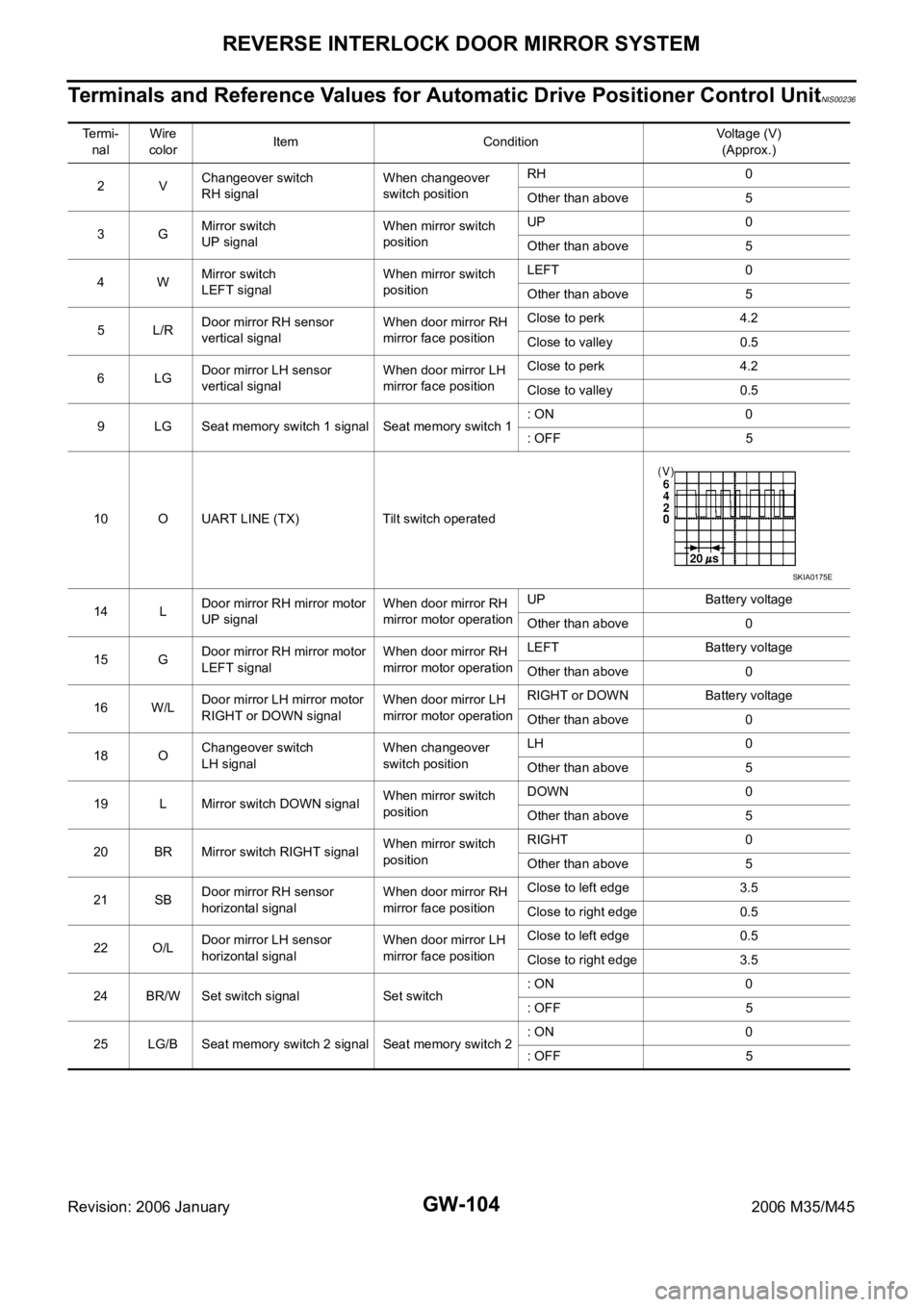
Terminals and Reference Values for Automatic Drive Positioner Control UnitNIS00236
Te r m i -
nalWire
colorItem ConditionVoltage (V)
(Approx.)
2VChangeover switch
RH signalWhen changeover
switch positionRH 0
Other than above 5
3GMirror switch
UP signalWhen mirror switch
positionUP 0
Other than above 5
4WMirror switch
LEFT signalWhen mirror switch
positionLEFT 0
Other than above 5
5L/RDoor mirror RH sensor
vertical signalWhen door mirror RH
mirror face positionClose to perk 4.2
Close to valley 0.5
6LGDoor mirror LH sensor
vertical signalWhen door mirror LH
mirror face positionClose to perk 4.2
Close to valley 0.5
9 LG Seat memory switch 1 signal Seat memory switch 1: ON 0
: OFF 5
10 O UART LINE (TX) Tilt switch operated
14 LDoor mirror RH mirror motor
UP signalWhen door mirror RH
mirror motor operationUP Battery voltage
Other than above 0
15 GDoor mirror RH mirror motor
LEFT signalWhen door mirror RH
mirror motor operationLEFT Battery voltage
Other than above 0
16 W/LDoor mirror LH mirror motor
RIGHT or DOWN signalWhen door mirror LH
mirror motor operationRIGHT or DOWN Battery voltage
Other than above 0
18 OChangeover switch
LH signalWhen changeover
switch positionLH 0
Other than above 5
19 L Mirror switch DOWN signalWhen mirror switch
positionDOWN 0
Other than above 5
20 BR Mirror switch RIGHT signalWhen mirror switch
positionRIGHT 0
Other than above 5
21 SBDoor mirror RH sensor
horizontal signalWhen door mirror RH
mirror face positionClose to left edge 3.5
Close to right edge 0.5
22 O/LDoor mirror LH sensor
horizontal signalWhen door mirror LH
mirror face positionClose to left edge 0.5
Close to right edge 3.5
24 BR/W Set switch signal Set switch: ON 0
: OFF 5
25 LG/B Seat memory switch 2 signal Seat memory switch 2: ON 0
: OFF 5
SKIA0175E
Page 3624 of 5621

REVERSE INTERLOCK DOOR MIRROR SYSTEM
GW-105
C
D
E
F
G
H
J
K
L
MA
B
GW
Revision: 2006 January2006 M35/M45
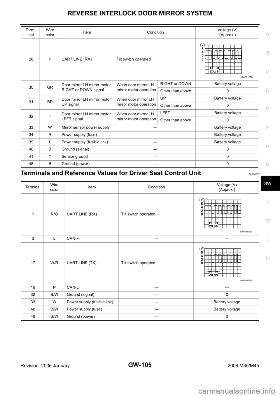
Terminals and Reference Values for Driver Seat Control UnitNIS00237
26 P UART LINE (RX) Tilt switch operated
30 GRDoor mirror LH mirror motor
RIGHT or DOWN signalWhen door mirror LH
mirror motor operationRIGHT or DOWN Battery voltage
Other than above 0
31 BRDoor mirror LH mirror motor
UP signalWhen door mirror LH
mirror motor operationUP Battery voltage
Other than above 0
32 TDoor mirror LH mirror motor
LEFT signalWhen door mirror LH
mirror motor operationLEFT Battery voltage
Other than above 0
33 W Mirror sensor power supply — Battery voltage
34 R Power supply (fuse) — Battery voltage
39 L Power supply (fusible link) — Battery voltage
40 B Ground (signal) — 0
41 Y Sensor ground — 0
48 B Ground (power) — 0 Termi-
nalWire
colorItem ConditionVoltage (V)
(Approx.)
SKIA0175E
Terminal Wire
colorItem ConditionVoltage (V)
(Approx.)
1 R/G UART LINE (RX) Tilt switch operated
3 L CAN-H — —
17 W/R UART LINE (TX) Tilt switch operated
19 P CAN-L — —
32 B/W Ground (signal) — 0
33 W Power supply (fusible link) — Battery voltage
40 B/W Power supply (fuse) — Battery voltage
48 B/W Ground (power) — 0
SKIA0175E
SKIA0175E
Page 4445 of 5621

LT-18
HEADLAMP (FOR USA) - CONVENTIONAL TYPE -
Revision: 2006 January2006 M35/M45
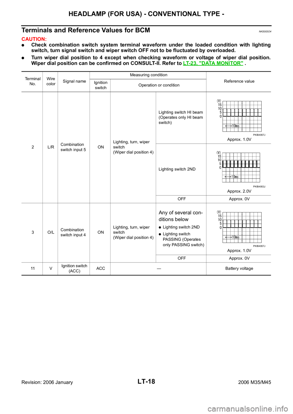
Terminals and Reference Values for BCMNKS003O4
CAUTION:
Check combination switch system terminal waveform under the loaded condition with lighting
switch, turn signal switch and wiper switch OFF not to be fluctuated by overloaded.
Turn wiper dial position to 4 except when checking waveform or voltage of wiper dial position.
Wiper dial position can be confirmed on CONSULT-II. Refer to LT-23, "
DATA MONITOR" .
Te r m i n a l
No.Wire
colorSignal nameMeasuring condition
Reference value
Ignition
switchOperation or condition
2L/RCombination
switch input 5ONLighting, turn, wiper
switch
(Wiper dial position 4)Lighting switch HI beam
(Operates only HI beam
switch)
Approx. 1.0V
Lighting switch 2ND
Approx. 2.0V
OFF Approx. 0V
3 O/LCombination
switch input 4ONLighting, turn, wiper
switch
(Wiper dial position 4)
Any of several con-
ditions below
Lighting switch 2ND
Lighting switch
PASSING (Operates
only PASSING switch)
Approx. 1.0V
OFF Approx. 0V
11 VIgnition switch
(ACC)ACC — Battery voltage
PKIB4957J
PKIB4953J
PKIB4957J
Page 4446 of 5621
HEADLAMP (FOR USA) - CONVENTIONAL TYPE -
LT-19
C
D
E
F
G
H
I
J
L
MA
B
LT
Revision: 2006 January2006 M35/M45
34 LCombination
switch output 3ONLighting, turn, wiper
switch
(Wiper dial position 4)
Any of several con-
ditions below
Lighting switch 2ND
Lighting switch HI
beam
(Operates only HI
beam switch)
Approx. 1.2V
OFF
Approx. 7.0 - 7.5V
35 SBCombination
switch output 2ONLighting, turn, wiper
switch
(Wiper dial position 4)
Any of several con-
ditions below
Lighting switch 2ND
Lighting switch
PASSING (Operates
only PASSING switch)
Approx. 1.2V
OFF
Approx. 7.0 - 7.5V
38 WIgnition switch
(ON) ON — Battery voltage
39 L CAN
H — — —
40 P CAN
L — — —
42 PBattery power
supplyOFF — Battery voltage
52 B Ground ON — Approx. 0V
55 WBattery power
supplyOFF — Battery voltage Terminal
No.Wire
colorSignal nameMeasuring condition
Reference value
Ignition
switchOperation or condition
PKIB4958J
PKIB4960J
PKIB4958J
PKIB4960J
Page 4447 of 5621

LT-20
HEADLAMP (FOR USA) - CONVENTIONAL TYPE -
Revision: 2006 January2006 M35/M45
Terminals and Reference Values for IPDM E/RNKS003O5
How to Perform Trouble DiagnosesNKS003O6
1. Confirm the symptom or customer complaint.
2. Understand operation description and function description. Refer to LT- 8 , "
System Description" .
3. Perform the Preliminary Check. Refer to LT- 2 0 , "
Preliminary Check" .
4. Check symptom and repair or replace the cause of malfunction.
5. Does the headlamp operate normally? If YES, GO TO 6. If NO, GO TO 4.
6. INSPECTION END
Preliminary CheckNKS003O7
CHECK POWER SUPPLY AND GROUND CIRCUIT
1. CHECK FUSE
Check for blown fuses.
Refer to LT-13, "Wiring Diagram — H/LAMP —" .
OK or NG
OK >> GO TO 2.
NG >> If fuse or fusible link is blown, be sure to eliminate cause of malfunction before installing new fuse
or fusible link. Refer to PG-3, "
POWER SUPPLY ROUTING CIRCUIT" .
Terminal
No.Wire
colorSignal nameMeasuring condition
Reference value
Ignition
switchOperation or condition
20 R Headlamp low (RH) ONLighting switch 2ND
positionOFF Approx. 0V
ON Battery voltage
27 BR Headlamp high (RH) ONLighting switch HIGH or
PASSING positionOFF Approx. 0V
ON Battery voltage
28 R/Y Headlamp high (LH) ONLighting switch HIGH or
PASSING positionOFF Approx. 0V
ON Battery voltage
30 R/B Headlamp low (LH) ONLighting switch 2ND
positionOFF Approx. 0V
ON Battery voltage
38 B Ground ON — Approx. 0V
49 L CAN
H — — —
50 P CAN
L — — —
51 B Ground ON — Approx. 0V
Unit Power source Fuse and fusible link No.
BCMBatteryF
21
Ignition switch ON or START position 1
Ignition switch ACC or ON position 6
IPDM E/R Battery71
72
74
76
78
86
Page 4480 of 5621

HEADLAMP (FOR USA) - XENON TYPE -
LT-53
C
D
E
F
G
H
I
J
L
MA
B
LT
Revision: 2006 January2006 M35/M45
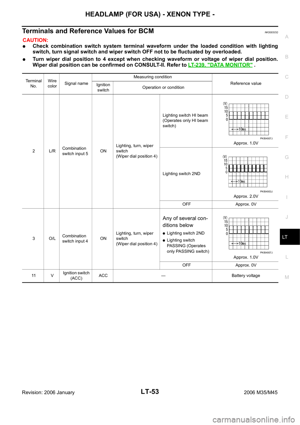
Terminals and Reference Values for BCMNKS003OQ
CAUTION:
Check combination switch system terminal waveform under the loaded condition with lighting
switch, turn signal switch and wiper switch OFF not to be fluctuated by overloaded.
Turn wiper dial position to 4 except when checking waveform or voltage of wiper dial position.
Wiper dial position can be confirmed on CONSULT-II. Refer to LT-239, "
DATA MONITOR" .
Terminal
No.Wire
colorSignal nameMeasuring condition
Reference value
Ignition
switchOperation or condition
2L/RCombination
switch input 5ONLighting, turn, wiper
switch
(Wiper dial position 4)Lighting switch HI beam
(Operates only HI beam
switch)
Approx. 1.0V
Lighting switch 2ND
Approx. 2.0V
OFF Approx. 0V
3O/LCombination
switch input 4ONLighting, turn, wiper
switch
(Wiper dial position 4)
Any of several con-
ditions below
Lighting switch 2ND
Lighting switch
PASSING (Operates
only PASSING switch)
Approx. 1.0V
OFF Approx. 0V
11 VIgnition switch
(ACC)ACC — Battery voltage
PKIB4957J
PKIB4953J
PKIB4957J
Page 4481 of 5621
LT-54
HEADLAMP (FOR USA) - XENON TYPE -
Revision: 2006 January2006 M35/M45
34 LCombination
switch output 3ONLighting, turn, wiper
switch
(Wiper dial position 4)
Any of several con-
ditions below
Lighting switch 2ND
Lighting switch HI
beam (Operates only
HI beam switch)
Approx. 1.2V
OFF
Approx. 7.0 - 7.5V
35 SBCombination
switch output 2ONLighting, turn, wiper
switch
(Wiper dial position 4)
Any of several con-
ditions below
Lighting switch 2ND
Lighting switch
PASSING (Operates
only PASSING switch)
Approx. 1.2V
OFF
Approx. 7.0 - 7.5V
38 WIgnition switch
(ON) ON — Battery voltage
39 L CAN
H — — —
40 P CAN
L — — —
42 PBattery power
supplyOFF — Battery voltage
52 B Ground ON — Approx. 0V
55 WBattery power
supplyOFF — Battery voltage Te r m i n a l
No.Wire
colorSignal nameMeasuring condition
Reference value
Ignition
switchOperation or condition
PKIB4958J
PKIB4960J
PKIB4958J
PKIB4960J