2006 INFINITI M35 Color wire
[x] Cancel search: Color wirePage 4864 of 5621

PDU (POWER DISTRIBUTION UNIT)
PG-37
C
D
E
F
G
H
I
J
L
MA
B
PG
Revision: 2006 January2006 M35/M45
Terminals and Reference Value for Intelligent Key UnitNKS004EG
Te r m i -
nalWire
ColorItemCondition
Voltage (V)
Approx. Ignition
Switch
PositionOperation or Conditions
1 SB Power source (Fuse) LOCK — Battery voltage
3 Y IPDM E/R status signal —Engine starting (During Cranking) 5
Other than above 2
8WPush-button ignition
switch
(LOCK LED)LOCK Push-button ignition switch is in LOCK position 0
—Push-button ignition switch is in any position
(Except LOCK position)1.2
9LPush-button ignition
switch
(ACC LED)ACC Push-button ignition switch is in ACC position 0
—Push-button ignition switch is in any position
(Except ACC position)1.2
10 VPush-button ignition
switch
(ON LED)ON Push-button ignition switch is in ON position 0
—Push-button ignition switch is in any position
(Except ON position)1.2
20 B Ground — — 0
30 L/W Ignition switch (ACC) ACC — Battery voltage
31 GR Ignition switch (ON) ON — Battery voltage
34 R PDU feedback signal LOCKPush-button ignition switch is in LOCK state, 30 sec-
onds after all doors closed1
Other than above 0
36 W Ignition signal 2LOCK — Battery voltage
ACC — Battery voltage
ON — 0
37 P CAN-L — — —
38 L CAN-H — — —
39 BR/W Push switch —Depress push-button ignition switch 0
Unpress push-button ignition switch Battery voltage
40 B Ground — — 0
41 Y Power source (Fuse) LOCK — Battery voltage
42 P PDU wake up signal LOCKPush-button ignition switch is in LOCk state, 30 sec-
onds after all doors closedBattery voltage
Other than above 0
44 BR Ignition signal 1LOCK — Battery voltage
ACC — Battery voltage
ON — 0
45 SB ACC signalLOCK — Battery voltage
ACC — 0
ON — 0
56 B Ground — — 0
57 L Power source (Fuse) LOCK — Battery voltage
72 B Ground — — 0
Page 4865 of 5621

PG-38
PDU (POWER DISTRIBUTION UNIT)
Revision: 2006 January2006 M35/M45
Terminals and Reference Value for PDUNKS004EH
Work FlowNKS004EI
1. Check the symptom and customer's requests.
2. Understand outline of system. Refer to PG-33, "
System Description" .
3. Confirm that Intelligent Key system operates normally.
Refer to BL-24, "
POWER DOOR LOCK SYSTEM" .
4. Repair or replace any malfunctioning parts.
Refer to PG-39, "
Trouble Diagnosis Symptom Chart" .
5. INSPECTION END
Te r m i -
nalWire
ColorItemCondition
Voltage (V)
Approx. Ignition
Switch
PositionOperation or Conditions
1 P PDU wake up signal LOCKPush-button ignition switch is in LOCK state, 30 sec-
onds after all doors closeBattery voltage
Other than above 0
4 BR Ignition signal 1LOCK — Battery voltage
ACC — Battery voltage
ON — 0
5 W Ignition signal 2LOCK — Battery voltage
ACC — Battery voltage
ON — 0
8 SB ACC signalLOCK — Battery voltage
ACC — 0
ON — 0
10 B Ground — — 0
11 Y IPDM E/R status signal —Engine starting (During Cranking) 5
Other than above 2
12 R PDU feedback signal LOCKPush-button ignition switch is in LOCK state, 30 sec-
onds after all doors close1
Other than above 0
14 SB Power source (Fuse) LOCK — Battery voltage
15 L Power source (F/L) LOCK — Battery voltage
16 W ACC power outputLOCK — 0
ACC — Battery voltage
ON — Battery voltage
17 G Power source (Fuse) LOCK — Battery voltage
18 BR ON power outputLOCK — 0
ACC — 0
ON — Battery voltage
Page 5028 of 5621

SUNROOF
RF-15
C
D
E
F
G
H
J
K
L
MA
B
RF
Revision: 2006 January2006 M35/M45
Terminals and Reference Value for BCMNIS0023T
Terminals and Reference Value for Sunroof Motor AssemblyNIS0023U
Te r m i -
nalWire
colorItem ConditionVoltage (V)
(Approx.)
12 P Front door switch (passenger side)OPEN (ON) 0
CLOSE (OFF) Battery voltage
38 W Power source (IGN) Ignition switch (ON or START) position Battery voltage
42 P Power source (Fuse) — Battery voltage
52 B Ground (power) — 0
53 BR RAP signalIgnition switch ON Battery voltage
Within 45 seconds after ignition switch is turned to
OFF positionBattery voltage
When driver side or passenger side door is opened
during retained power operation.0
54 O Power window power supply (BAT) — Battery voltage
55 W Power source (Fusible link) — Battery voltage
62 V Front door switch (driver side)OPEN (ON) 0
CLOSE (OFF) Battery voltage
Te r m i -
nalWire
colorItem ConditionVoltage (V)
(Approx.)
1 O BAT power supply (BCM) — Battery voltage
4LGSunroof (TILT DOWN/SLIDE
OPEN) switch signalIgnition switch ON and sunroof switch in
TILT DOWN / SLIDE OPEN position0
Other than above Battery voltage
6YRAP signalIgnition switch ON Battery voltage
Within 45 seconds after ignition switch is turned to
OFF positionBattery voltage
When driver side or passenger side door is opened
during retained power operation.0
8 B Ground — 0
9 Y Sunroof switch ground — 0
11 LSunroof (TILT UP/SLIDE CLOSE)
switch signalIgnition switch ON and sunroof switch in
TILT UP / SLIDE CLOSE position0
Other than above Battery voltage
Page 5112 of 5621

PRE-CRASH SEAT BELT
SB-13
C
D
E
F
G
I
J
K
L
MA
B
SB
Revision: 2006 January2006 M35/M45
Terminals and Reference Value for Pre-Crash Seat Belt Control UnitNHS00083
Work FlowNHS00084
1. Check the symptom and customer's requests.
2. Understand the system description. Refer to SB-3, "
System Description" .
3. Perform the preliminary check. Refer to SB-16, "
Preliminary Check" .
4. Check the self-diagnosis, results using CONSULT-II. Refer to SB-14, "
CONSULT-II Function (PRECRASH
SEATBELT)" .
5. Based on the trouble diagnosis chart, repair or replace the cause of the malfunction. Refer to SB-16,
"Diagnoses Symptom Chart" .
6. Does pre-crash seat belt system operate normally?
OK: GO TO 7.
NG: GO TO 4.
7. INSPECTION END
Terminal Wire Color Item ConditionVoltage [V]
(Approx.)
1G/RSeat belt motor RH release direction
signalSeat belt motor RH operation Battery voltage
Other than above 0
2 W Power source (BAT) – Battery voltage
3G/YSeat belt motor RH fastened direction
signalSeat belt motor RH operation Battery voltage
Other than above 0
4GY/WSeat belt motor LH fastened direction
signalSeat belt motor LH operation Battery voltage
Other than above 0
5 B/Y Ground (Driver circuit) – 0
6L/YSeat belt motor LH release direction
signalSeat belt motor LH operation Battery voltage
Other than above 0
7 G/Y Seat belt indicator signalWhen driver side seat belt is fastened Battery voltage
When driver side seat belt is un-fastened 0
When driver side seat belt is fastened and
system malfunctionBattery
voltage
0
8 LG Seat belt buckle switch RHWhen seat belt is fastened 5
When seat belt is un-fastened 0
10 SB Seat belt buckle switch LHWhen seat belt is fastened Battery voltage
When seat belt is un-fastened 0
13 W/G Power source (IGN) Ignition switch ON or START Battery voltage
16 WBrake pedal stroke sensor output sig-
nal 1Brake pedal is fully released operation 1
Brake pedal is slightly depressed operation 4
18 RPower source (Brake pedal stroke sen-
sor)
–5
20 GBrake pedal stroke sensor output sig-
nal 2Brake pedal is fully released operation 4
Brake pedal is slightly depressed operation 1
21 B Ground (Brake pedal stroke sensor) – 0
22 P CAN-L – -
24 L CAN-H – -
25 – Ground (Shield wire) – 0
26 B/Y Ground (Control circuit) – 0
Page 5211 of 5621

SE-30
AUTOMATIC DRIVE POSITIONER
Revision: 2006 January2006 M35/M45
Terminals and Reference Values for BCMNIS0025W
Terminals and Reference Value for Intelligent Key UnitNIS0025X
Termi-
nal Wire
colorItem ConditionVoltage (V)
(Approx)
11 V Power source (ACC)Ignition switch
(ACC or ON position)Battery voltage
37 LG Key switch signalKey switch ON (Key is inserted in key
slot)Battery voltage
Key switch OFF (Key is remove from
key slot)0
38 W Power source (IGN)Ignition switch
(ON or START position)Battery voltage
39 L CAN-H — —
40 P CAN-L — —
42 P Power source (Fuse) — Battery voltage
52 B Ground — 0
55 W Power source (Fusible link) — Battery voltage
62 V Drive side door switch ON (Open)
OFF (Closed) 0 Battery voltage
Te r m i -
nalWire
ColorItemCondition
Voltage (V)
Approx. Ignition
Switch
PositionOperation or Conditions
1 SB Power source (Fuse) — — Battery voltage
19 BR/Y Key switch signal LOCKInsert Intelligent Key into key slot. Battery voltage
Remove Intelligent Key from key slot. 0
20 B Ground ON — 0
27 V P range switch —Selector lever is in “P” position. 0
Other than above Battery voltage
37 P CAN-L — — —
38 L CAN-H — — —
40 B Ground ON — 0
41 Y Power source (Fuse) — — Battery voltage
56 B Ground ON — 0
57 L Power source (Fuse) — — Battery voltage
58 OA/T device power
supply —Wake up state Battery voltage
Sleep state 0
72 B Ground ON 0
Page 5212 of 5621

AUTOMATIC DRIVE POSITIONER
SE-31
C
D
E
F
G
H
J
K
L
MA
B
SE
Revision: 2006 January2006 M35/M45
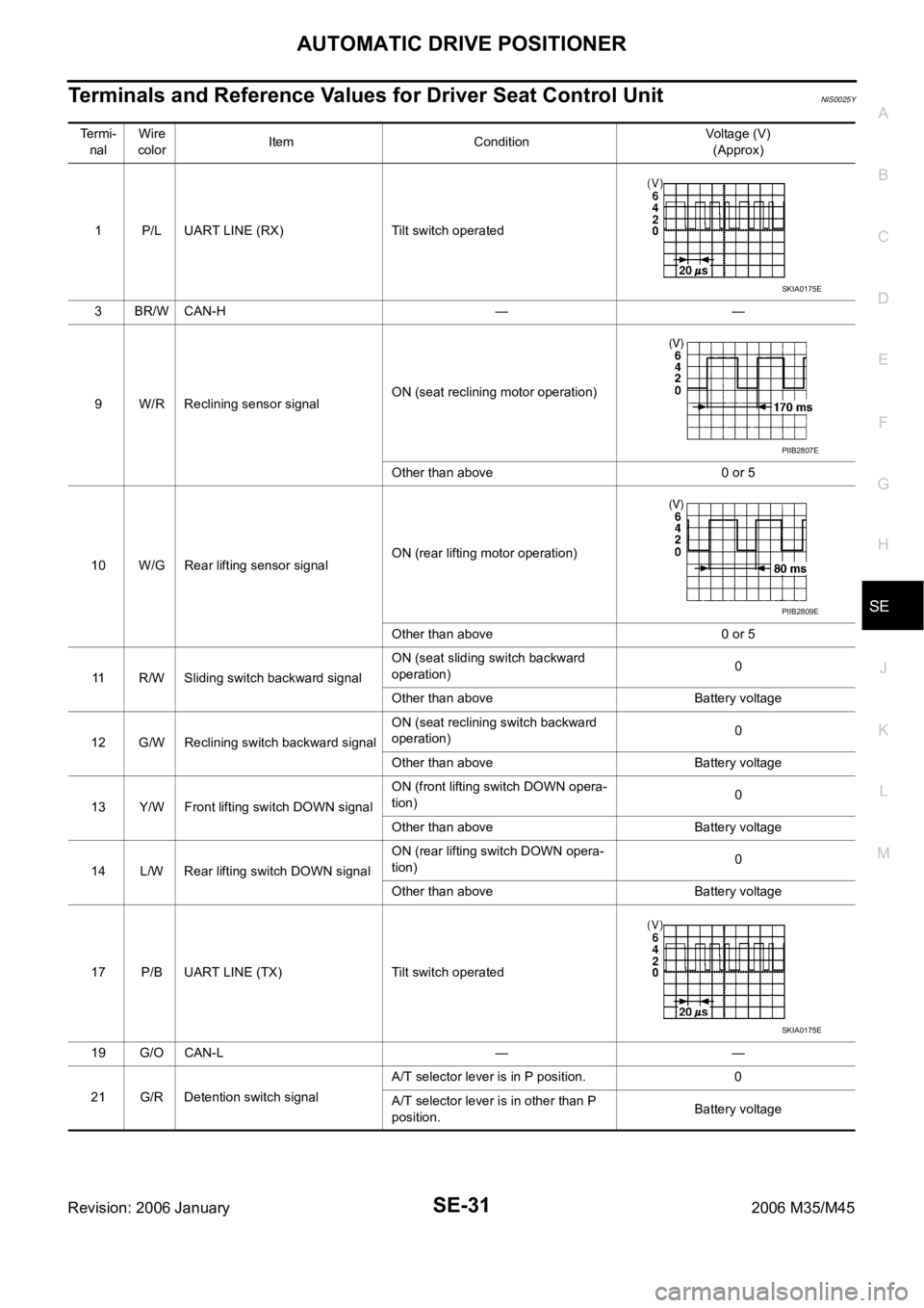
Terminals and Reference Values for Driver Seat Control UnitNIS0025Y
Te r m i -
nalWire
colorItem ConditionVoltage (V)
(Approx)
1 P/L UART LINE (RX) Tilt switch operated
3BR/WCAN-H — —
9 W/R Reclining sensor signalON (seat reclining motor operation)
Other than above 0 or 5
10 W/G Rear lifting sensor signalON (rear lifting motor operation)
Other than above 0 or 5
11 R/W Sliding switch backward signalON (seat sliding switch backward
operation)0
Other than above Battery voltage
12 G/W Reclining switch backward signalON (seat reclining switch backward
operation)0
Other than above Battery voltage
13 Y/W Front lifting switch DOWN signalON (front lifting switch DOWN opera-
tion)0
Other than above Battery voltage
14 L/W Rear lifting switch DOWN signalON (rear lifting switch DOWN opera-
tion)0
Other than above Battery voltage
17 P/B UART LINE (TX) Tilt switch operated
19 G/O CAN-L — —
21 G/R Detention switch signalA/T selector lever is in P position. 0
A/T selector lever is in other than P
position.Battery voltage
SKIA0175E
PIIB2807E
PIIB2809E
SKIA0175E
Page 5213 of 5621

SE-32
AUTOMATIC DRIVE POSITIONER
Revision: 2006 January2006 M35/M45
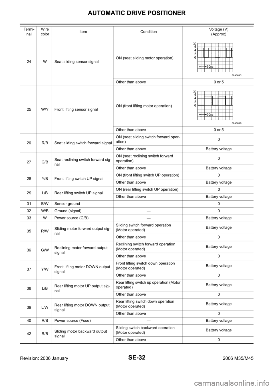
24 W Seat sliding sensor signalON (seat sliding motor operation)
Other than above 0 or 5
25 W/Y Front lifting sensor signalON (front lifting motor operation)
Other than above 0 or 5
26 R/B Seat sliding switch forward signalON (seat sliding switch forward oper-
ation)0
Other than above Battery voltage
27 G/BSeat reclining switch forward sig-
nalON (seat reclining switch forward
operation)0
Other than above Battery voltage
28 Y/B Front lifting switch UP signalON (front lifting switch UP operation) 0
Other than above Battery voltage
29 L/B Rear lifting switch UP signalON (rear lifting switch UP operation) 0
Other than above Battery voltage
31 B/W Sensor ground — 0
32 W/B Ground (signal) — 0
33 W Power source (C/B) — Battery voltage
35 R/WSliding motor forward output sig-
nalSliding switch forward operation
(Motor operated)Battery voltage
Other than above 0
36 G/WReclining motor forward output
signalReclining switch forward operation
(Motor operated)Battery voltage
Other than above 0
37 Y/WFront lifting motor DOWN output
signalFront lifting switch down operation
(Motor operated)Battery voltage
Other than above 0
38 L/BRear lifting motor UP output sig-
nalRear lifting switch up operation (Motor
operated)Battery voltage
Other than above 0
39 L/WRear lifting motor DOWN output
signalRear lifting switch down operation
(Motor operated)Battery voltage
Other than above 0
40 R/B Power source (Fuse) — Battery voltage
42 R/BSliding motor backward output
signalSliding switch backward operation
(Motor operated)Battery voltage
Other than above 0 Te r m i -
nalWire
colorItem ConditionVoltage (V)
(Approx)
SIIA0690J
SIIA0691J
Page 5214 of 5621

AUTOMATIC DRIVE POSITIONER
SE-33
C
D
E
F
G
H
J
K
L
MA
B
SE
Revision: 2006 January2006 M35/M45
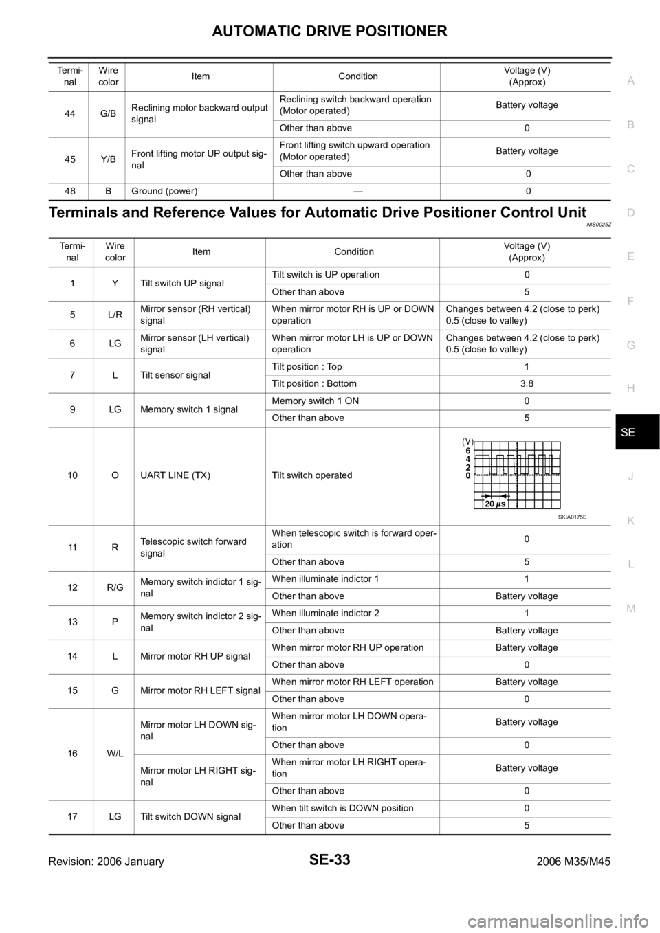
Terminals and Reference Values for Automatic Drive Positioner Control UnitNIS0025Z
44 G/BReclining motor backward output
signalReclining switch backward operation
(Motor operated)Battery voltage
Other than above 0
45 Y/BFront lifting motor UP output sig-
nalFront lifting switch upward operation
(Motor operated)Battery voltage
Other than above 0
48 B Ground (power) — 0 Te r m i -
nalWire
colorItem ConditionVoltage (V)
(Approx)
Te r m i -
nal Wire
colorItem ConditionVoltage (V)
(Approx)
1 Y Tilt switch UP signalTilt switch is UP operation 0
Other than above 5
5L/RMirror sensor (RH vertical)
signalWhen mirror motor RH is UP or DOWN
operationChanges between 4.2 (close to perk)
0.5 (close to valley)
6LGMirror sensor (LH vertical)
signalWhen mirror motor LH is UP or DOWN
operationChanges between 4.2 (close to perk)
0.5 (close to valley)
7 L Tilt sensor signalTilt position : Top 1
Tilt position : Bottom 3.8
9 LG Memory switch 1 signalMemory switch 1 ON 0
Other than above 5
10 O UART LINE (TX) Tilt switch operated
11 RTelescopic switch forward
signalWhen telescopic switch is forward oper-
ation0
Other than above 5
12 R/GMemory switch indictor 1 sig-
nalWhen illuminate indictor 1 1
Other than above Battery voltage
13 PMemory switch indictor 2 sig-
nalWhen illuminate indictor 2 1
Other than above Battery voltage
14 L Mirror motor RH UP signalWhen mirror motor RH UP operation Battery voltage
Other than above 0
15 G Mirror motor RH LEFT signalWhen mirror motor RH LEFT operation Battery voltage
Other than above 0
16 W/LMirror motor LH DOWN sig-
nalWhen mirror motor LH DOWN opera-
tionBattery voltage
Other than above 0
Mirror motor LH RIGHT sig-
nalWhen mirror motor LH RIGHT opera-
tionBattery voltage
Other than above 0
17 LG Tilt switch DOWN signalWhen tilt switch is DOWN position 0
Other than above 5
SKIA0175E