2006 INFINITI M35 fog light bulb
[x] Cancel search: fog light bulbPage 4430 of 5621

LT-3
C
D
E
F
G
H
I
J
L
MA
B
LT
Revision: 2006 January2006 M35/M45 OUTLINE ...........................................................136
AFS OPERATION .............................................137
HEADLAMP AUTO AIMING OPERATION ........139
CAN COMMUNICATION SYSTEM DESCRIP-
TION ..................................................................139
CAN COMMUNICATION UNIT .........................139
Component Parts Description ..............................140
AFS CONTROL UNIT .......................................140
SWIVEL ACTUATOR ........................................140
AIMING MOTOR ...............................................140
AFS SWITCH ....................................................141
HEIGHT SENSOR ............................................141
STEERING ANGLE SENSOR ..........................141
IPDM E/R ..........................................................141
ECM ..................................................................141
TCM ..................................................................141
UNIFIED METER AND A/C AMP. .....................141
COMBINATION METER ...................................141
Schematic ............................................................142
Wiring Diagram — AFS — ...................................143
Terminals and Reference Values for AFS Control
Unit .......................................................................149
How to Proceed with Trouble Diagnosis ..............151
Preliminary Check ................................................151
CONSULT-II Function (ADAPTIVE LIGHT) ..........152
CONSULT-II BASIC OPERATION .....................152
WORK SUPPORT (STEERING ANGLE SEN-
SOR ADJUSTMENT) ........................................153
WORK SUPPORT (LEVELIZER ADJUSTMENT)
.153
SELF-DIAG RESULTS ......................................154
DATA MONITOR ...............................................158
ACTIVE TEST ...................................................160
Symptom Chart ....................................................161
DTC B2503 SWIVEL ACTUATOR RH .................162
DTC B2504 SWIVEL ACTUATOR LH ..................168
DTC B2514 HI SEN UNUSUAL RR .....................174
DTC B2521 ECU CIRC ........................................178
AFS Operation Check (Function Test) .................181
Auto Aiming Operation Check (Function Test) .....183
AFS Switch Does Not Operate .............................185
Auto Aiming Does Not Operate (Check Aiming
Motor System Circuit) ..........................................
.187
AFS OFF Indicator Does Not Operate .................190
Removal and Installation of Steering Angle Sensor .190
Removal and Installation of Front Combination
Lamp ....................................................................190
Removal and Installation of AFS Control Unit ......191
REMOVAL ........................................................
.191
INSTALLATION .................................................191
Removal and Installation of AFS Switch ..............191
REMOVAL ........................................................
.191
INSTALLATION .................................................191
Removal and Installation of Height Sensor ..........192
REMOVAL ........................................................
.192
INSTALLATION .................................................192
FRONT FOG LAMP ................................................193
Component Parts and Harness Connector Location .193
System Description ..............................................193OUTLINE ...........................................................194
COMBINATION SWITCH READING FUNCTION .195
EXTERIOR LAMP BATTERY SAVER CONTROL .195
CAN Communication System Description ............195
CAN Communication Unit .....................................195
Schematic .............................................................196
Wiring Diagram — F/FOG — ................................197
Terminals and Reference Values for BCM ............201
Terminals and Reference Values for IPDM E/R ....202
How to Perform Trouble Diagnoses .....................202
Preliminary Check ................................................202
CHECK POWER SUPPLY AND GROUND CIR-
CUIT ..................................................................202
CONSULT-II Functions (BCM) ..............................203
CONSULT-II Functions (IPDM E/R) ......................203
Front Fog Lamps Do Not Illuminate (Both Sides) . 204
Front Fog Lamp Does Not Illuminate (One Side) . 207
Front Fog Lamps Do Not Turn OFF ......................208
Aiming Adjustment ................................................209
Bulb Replacement ................................................210
Removal and Installation ......................................210
REMOVAL ........................................................
.210
INSTALLATION .................................................210
TURN SIGNAL AND HAZARD WARNING LAMPS .211
Component Parts and Harness Connector Location .211
System Description ...............................................211
TURN SIGNAL OPERATION ............................211
HAZARD LAMP OPERATION ...........................212
COMBINATION SWITCH READING FUNCTION .213
CAN Communication System Description ............213
CAN Communication Unit .....................................213
Schematic .............................................................214
Wiring Diagram — TURN — .................................215
Terminals and Reference Values for BCM ............219
How to Perform Trouble Diagnoses .....................220
Preliminary Check ................................................221
CHECK POWER SUPPLY AND GROUND CIR-
CUIT ..................................................................221
CONSULT-II Functions (BCM) ..............................223
CONSULT-II BASIC OPERATION .....................223
DATA MONITOR ...............................................224
ACTIVE TEST ...................................................224
Turn Signal Lamp Does Not Operate ...................225
H a z a r d W a r n i n g L a m p D o e s N o t O p e r a t e B u t T u r n
Signal Lamp Operate ............................................227
Turn Signal Indicator Lamp Does Not Operate ....228
Bulb Replacement/Removal and Installation of Side
Turn Signal Lamp .................................................229
REMOVAL ........................................................
.229
INSTALLATION .................................................229
Bulb Replacement (Front Turn Signal Lamp) .......229
Bulb Replacement (Rear Turn Signal Lamp) ........229
Removal and Installation of Front Turn Signal Lamp .229
Removal and Installation of Rear Turn Signal Lamp .229
LIGHTING AND TURN SIGNAL SWITCH ..............230
Removal and Installation ......................................230
REMOVAL ........................................................
.230
INSTALLATION .................................................230
Switch Circuit Inspection ......................................230
Page 4637 of 5621

LT-210
FRONT FOG LAMP
Revision: 2006 January2006 M35/M45
Bulb ReplacementNKS003RI
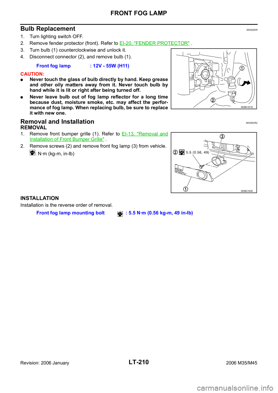
1. Turn lighting switch OFF.
2. Remove fender protector (front). Refer to EI-20, "
FENDER PROTECTOR" .
3. Turn bulb (1) counterclockwise and unlock it.
4. Disconnect connector (2), and remove bulb (1).
CAUTION:
Never touch the glass of bulb directly by hand. Keep grease
and other oily matters away from it. Never touch bulb by
hand while it is lit or right after being turned off.
Never leave bulb out of fog lamp reflector for a long time
because dust, moisture smoke, etc. may affect the perfor-
mance of fog lamp. When replacing bulb, be sure to replace
it with new one.
Removal and InstallationNKS003RJ
REMOVAL
1. Remove front bumper grille (1). Refer to EI-13, "Removal and
Installation of Front Bumper Grille" .
2. Remove screws (2) and remove front fog lamp (3) from vehicle.
: Nꞏm (kg-m, in-lb)
INSTALLATION
Installation is the reverse order of removal.Front fog lamp : 12V - 55W (H11)
SKIB4161E
SKIB4162E
Front fog lamp mounting bolt : 5.5 Nꞏm (0.56 kg-m, 49 in-lb)
Page 4742 of 5621

BULB SPECIFICATIONS
LT-315
C
D
E
F
G
H
I
J
L
MA
B
LT
Revision: 2006 January2006 M35/M45
BULB SPECIFICATIONSPFP:26297
HeadlampNKS003TQ
Exterior LampNKS003TR
Interior Lamp/IlluminationNKS003TS
NOTE:
This lamp is used as both front ashtray and front cigarette lighter. Item Wattage (W)
Low (Halogen type)55 (H1)
Low (Xenon type)35 (D2S)
High60 (HB3)
Item Wattage (W)
Front combination lampFront turn signal lamp 21
Parking lamp (Clearance lamp) 5
Front side marker lamp 5
Rear combination lampStop/Tail lamp LED
Rear turn signal lamp 21 (amber)
Rear side marker lamp LED
Back-up lamp18
Side turn signal lamp5
Front fog lamp55 (H11)
License plate lamp5
High-mounted stop lampLED
Item Wattage (W)
Map lamp8
Personal lamp8
Trunk room lampUpper
5
Lower
Front ashtray and front cigarette lighter illumination
NOTE1.4
Rear ashtray illumination1.4
Ste p lamp5
Vanity mirror lamp1.8
Center console indirect illuminationLED
Glove box lamp1.4
Foot lampDriver side
3.4
Passenger side
Kicking plateDriver side
LED
Passenger side
Power window indirect illuminationLED