Page 5267 of 5621
SE-86
AUTOMATIC DRIVE POSITIONER
Revision: 2006 January2006 M35/M45
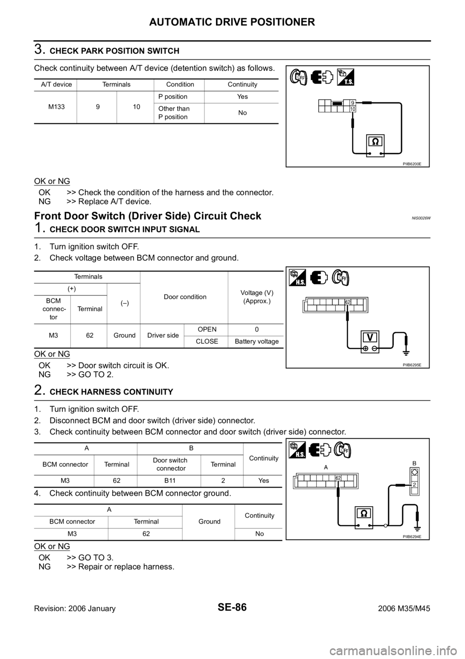
3. CHECK PARK POSITION SWITCH
Check continuity between A/T device (detention switch) as follows.
OK or NG
OK >> Check the condition of the harness and the connector.
NG >> Replace A/T device.
Front Door Switch (Driver Side) Circuit Check NIS0026W
1. CHECK DOOR SWITCH INPUT SIGNAL
1. Turn ignition switch OFF.
2. Check voltage between BCM connector and ground.
OK or NG
OK >> Door switch circuit is OK.
NG >> GO TO 2.
2. CHECK HARNESS CONTINUITY
1. Turn ignition switch OFF.
2. Disconnect BCM and door switch (driver side) connector.
3. Check continuity between BCM connector and door switch (driver side) connector.
4. Check continuity between BCM connector ground.
OK or NG
OK >> GO TO 3.
NG >> Repair or replace harness.
A/T device Terminals Condition Continuity
M133 9 10P position Yes
Other than
P positionNo
PIIB6200E
Terminals
Door conditionVoltage (V)
(Approx.) (+)
(–) BCM
connec-
torTerminal
M3 62 Ground Driver sideOPEN 0
CLOSE Battery voltage
PIIB6295E
AB
Continuity
BCM connector TerminalDoor switch
connectorTerminal
M3 62 B11 2 Yes
A
GroundContinuity
BCM connector Terminal
M3 62 No
PIIB6294E
Page 5268 of 5621
AUTOMATIC DRIVE POSITIONER
SE-87
C
D
E
F
G
H
J
K
L
MA
B
SE
Revision: 2006 January2006 M35/M45
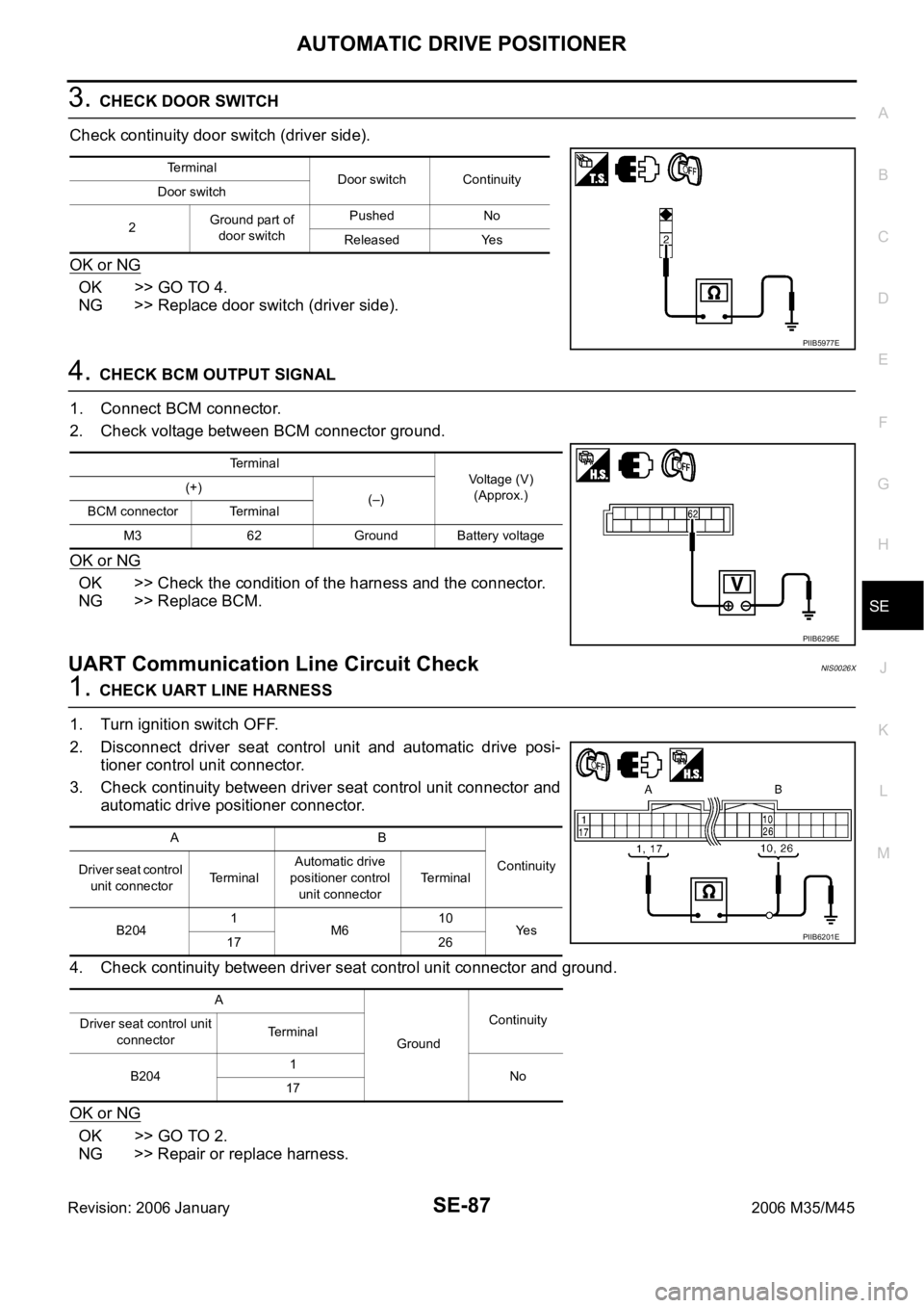
3. CHECK DOOR SWITCH
Check continuity door switch (driver side).
OK or NG
OK >> GO TO 4.
NG >> Replace door switch (driver side).
4. CHECK BCM OUTPUT SIGNAL
1. Connect BCM connector.
2. Check voltage between BCM connector ground.
OK or NG
OK >> Check the condition of the harness and the connector.
NG >> Replace BCM.
UART Communication Line Circuit CheckNIS0026X
1. CHECK UART LINE HARNESS
1. Turn ignition switch OFF.
2. Disconnect driver seat control unit and automatic drive posi-
tioner control unit connector.
3. Check continuity between driver seat control unit connector and
automatic drive positioner connector.
4. Check continuity between driver seat control unit connector and ground.
OK or NG
OK >> GO TO 2.
NG >> Repair or replace harness.
Terminal
Door switch Continuity
Door switch
2Ground part of
door switchPushed No
Released Yes
PIIB5977E
Terminal
Voltage (V)
(Approx.) (+)
(–)
BCM connector Terminal
M3 62 Ground Battery voltage
PIIB6295E
AB
Continuity
Driver seat control
unit connectorTerminalAutomatic drive
positioner control
unit connectorTerminal
B2041
M610
Ye s
17 26
A
GroundContinuity
Driver seat control unit
connectorTerminal
B2041
No
17
PIIB6201E
Page 5269 of 5621
SE-88
AUTOMATIC DRIVE POSITIONER
Revision: 2006 January2006 M35/M45
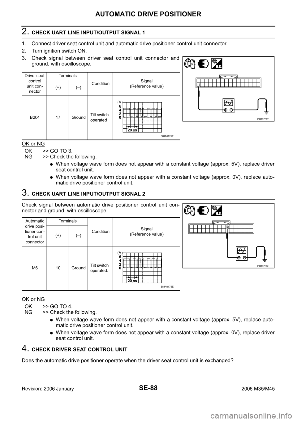
2. CHECK UART LINE INPUT/OUTPUT SIGNAL 1
1. Connect driver seat control unit and automatic drive positioner control unit connector.
2. Turn ignition switch ON.
3. Check signal between driver seat control unit connector and
ground, with oscilloscope.
OK or NG
OK >> GO TO 3.
NG >> Check the following.
When voltage wave form does not appear with a constant voltage (approx. 5V), replace driver
seat control unit.
When voltage wave form does not appear with a constant voltage (approx. 0V), replace auto-
matic drive positioner control unit.
3. CHECK UART LINE INPUT/OUTPUT SIGNAL 2
Check signal between automatic drive positioner control unit con-
nector and ground, with oscilloscope.
OK or NG
OK >> GO TO 4.
NG >> Check the following.
When voltage wave form does not appear with a constant voltage (approx. 5V), replace auto-
matic drive positioner control unit.
When voltage wave form does not appear with a constant voltage (approx. 0V), replace driver
seat control unit.
4. CHECK DRIVER SEAT CONTROL UNIT
Does the automatic drive positioner operate when the driver seat control unit is exchanged?
Driver seat
control
unit con-
nectorTe r m i n a l s
ConditionSignal
(Reference value)
(+) (–)
B204 17 GroundTilt switch
operated
PIIB6202E
SKIA0175E
Automatic
drive posi-
tioner con-
trol unit
connectorTe r m i n a l s
ConditionSignal
(Reference value)
(+) (–)
M6 10 GroundTilt switch
operated.
PIIB6203E
SKIA0175E
Page 5270 of 5621
AUTOMATIC DRIVE POSITIONER
SE-89
C
D
E
F
G
H
J
K
L
MA
B
SE
Revision: 2006 January2006 M35/M45
OK or NG
OK >> Replace driver seat control unit.
NG >> Replace automatic drive positioner control unit.
Lumber Support Circuit CheckNIS0026Y
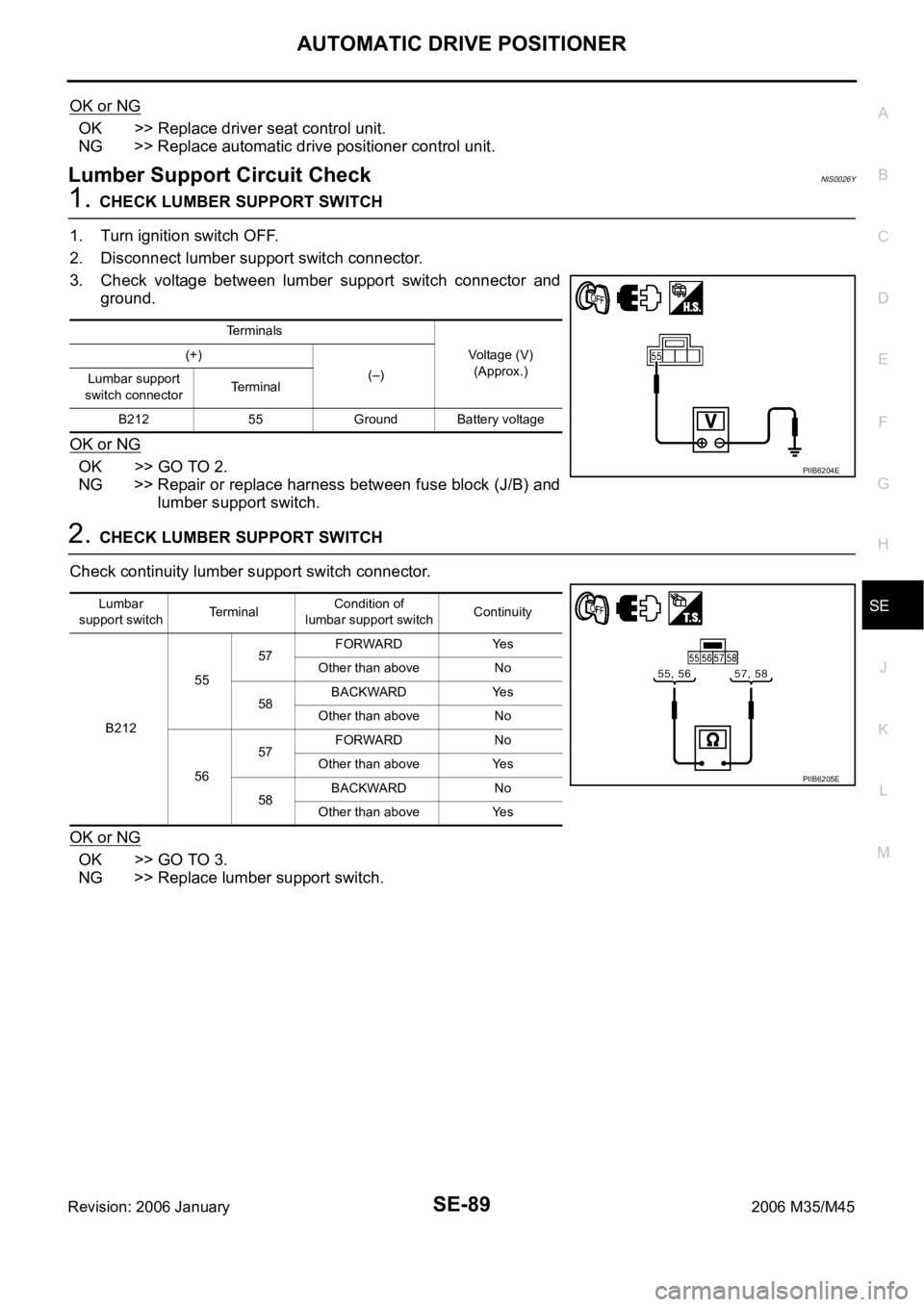
1. CHECK LUMBER SUPPORT SWITCH
1. Turn ignition switch OFF.
2. Disconnect lumber support switch connector.
3. Check voltage between lumber support switch connector and
ground.
OK or NG
OK >> GO TO 2.
NG >> Repair or replace harness between fuse block (J/B) and
lumber support switch.
2. CHECK LUMBER SUPPORT SWITCH
Check continuity lumber support switch connector.
OK or NG
OK >> GO TO 3.
NG >> Replace lumber support switch.
Terminals
Voltage (V)
(Approx.) (+)
(–)
Lumbar support
switch connectorTerminal
B212 55 Ground Battery voltage
PIIB6204E
Lumbar
support switchTerminalCondition of
lumbar support switchContinuity
B2125557FORWARD Yes
Other than above No
58BACKWARD Yes
Other than above No
5657FORWARD No
Other than above Yes
58BACKWARD No
Other than above Yes
PIIB6205E
Page 5285 of 5621
SE-104
POWER SEAT(REAR)
Revision: 2006 January2006 M35/M45
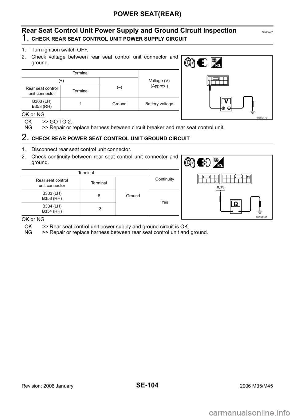
Rear Seat Control Unit Power Supply and Ground Circuit InspectionNIS0027A
1. CHECK REAR SEAT CONTROL UNIT POWER SUPPLY CIRCUIT
1. Turn ignition switch OFF.
2. Check voltage between rear seat control unit connector and
ground.
OK or NG
OK >> GO TO 2.
NG >> Repair or replace harness between circuit breaker and rear seat control unit.
2. CHECK REAR POWER SEAT CONTROL UNIT GROUND CIRCUIT
1. Disconnect rear seat control unit connector.
2. Check continuity between rear seat control unit connector and
ground.
OK or NG
OK >> Rear seat control unit power supply and ground circuit is OK.
NG >> Repair or replace harness between rear seat control unit and ground.
Terminal
Voltage (V)
(Approx.) (+)
(–)
Rear seat control
unit connectorTerminal
B303 (LH)
B353 (RH)1 Ground Battery voltage
PIIB5917E
Te r m i n a l
Continuity
Rear seat control
unit connectorTerminal
Ground B303 (LH)
B353 (RH)8
Ye s
B304 (LH)
B354 (RH)13
PIIB5918E
Page 5286 of 5621
POWER SEAT(REAR)
SE-105
C
D
E
F
G
H
J
K
L
MA
B
SE
Revision: 2006 January2006 M35/M45
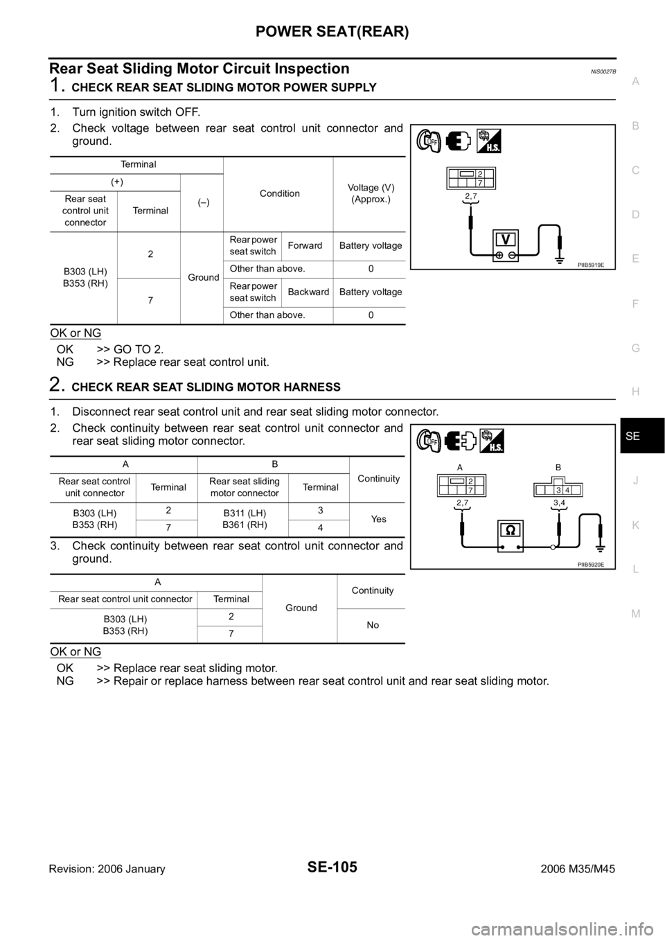
Rear Seat Sliding Motor Circuit InspectionNIS0027B
1. CHECK REAR SEAT SLIDING MOTOR POWER SUPPLY
1. Turn ignition switch OFF.
2. Check voltage between rear seat control unit connector and
ground.
OK or NG
OK >> GO TO 2.
NG >> Replace rear seat control unit.
2. CHECK REAR SEAT SLIDING MOTOR HARNESS
1. Disconnect rear seat control unit and rear seat sliding motor connector.
2. Check continuity between rear seat control unit connector and
rear seat sliding motor connector.
3. Check continuity between rear seat control unit connector and
ground.
OK or NG
OK >> Replace rear seat sliding motor.
NG >> Repair or replace harness between rear seat control unit and rear seat sliding motor.
Terminal
ConditionVoltage (V)
(Approx.) (+)
(–) Rear seat
control unit
connectorTerminal
B303 (LH)
B353 (RH)2
GroundRear power
seat switch Forward Battery voltage
Other than above. 0
7Rear power
seat switch Backward Battery voltage
Other than above. 0
PIIB5919E
AB
Continuity
Rear seat control
unit connectorTerminalRear seat sliding
motor connectorTerminal
B303 (LH)
B353 (RH)2
B311 (LH)
B361 (RH)3
Ye s
74
A
GroundContinuity
Rear seat control unit connector Terminal
B303 (LH)
B353 (RH)2
No
7
PIIB5920E
Page 5287 of 5621
SE-106
POWER SEAT(REAR)
Revision: 2006 January2006 M35/M45
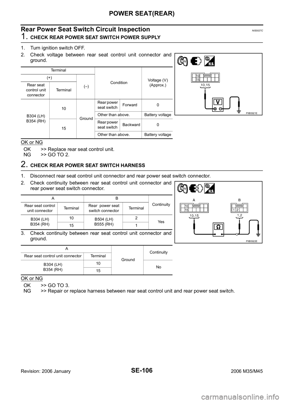
Rear Power Seat Switch Circuit InspectionNIS0027C
1. CHECK REAR POWER SEAT SWITCH POWER SUPPLY
1. Turn ignition switch OFF.
2. Check voltage between rear seat control unit connector and
ground.
OK or NG
OK >> Replace rear seat control unit.
NG >> GO TO 2.
2. CHECK REAR POWER SEAT SWITCH HARNESS
1. Disconnect rear seat control unit connector and rear power seat switch connector.
2. Check continuity between rear seat control unit connector and
rear power seat switch connector.
3. Check continuity between rear seat control unit connector and
ground.
OK or NG
OK >> GO TO 3.
NG >> Repair or replace harness between rear seat control unit and rear power seat switch.
Terminal
ConditionVoltage (V)
(Approx.) (+)
(–) Rear seat
control unit
connectorTerminal
B304 (LH)
B354 (RH)10
GroundRear power
seat switch Forward 0
Other than above. Battery voltage
15Rear power
seat switch Backward 0
Other than above. Battery voltage
PIIB5921E
AB
Continuity
Rear seat control
unit connectorTe r m i n a lRear power seat
switch connectorTerminal
B304 (LH)
B354 (RH)10
B504 (LH)
B555 (RH)2
Ye s
15 1
A
GroundContinuity
Rear seat control unit connector Terminal
B304 (LH)
B354 (RH)10
No
15
PIIB5922E
Page 5289 of 5621
SE-108
POWER SEAT(REAR)
Revision: 2006 January2006 M35/M45
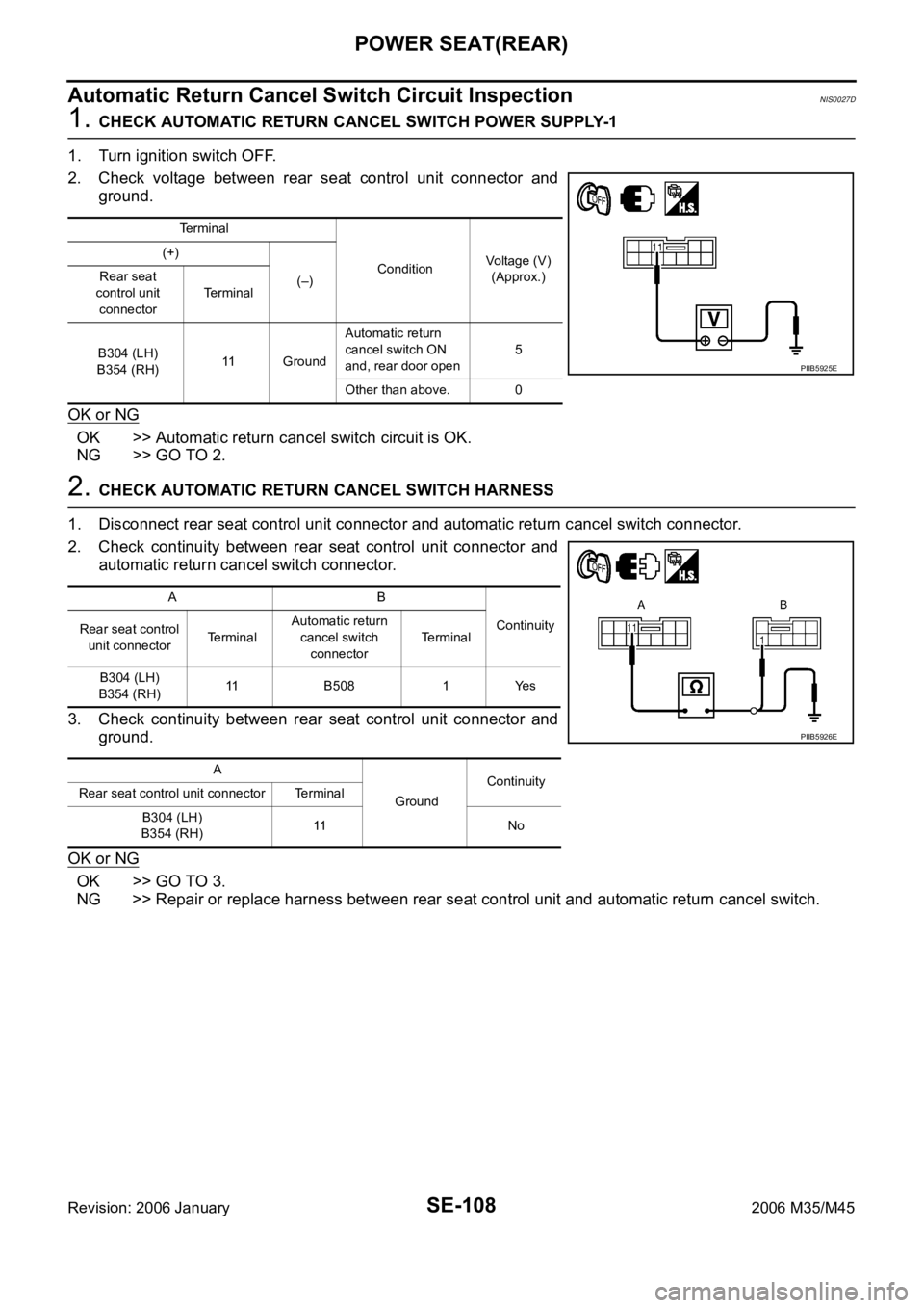
Automatic Return Cancel Switch Circuit InspectionNIS0027D
1. CHECK AUTOMATIC RETURN CANCEL SWITCH POWER SUPPLY-1
1. Turn ignition switch OFF.
2. Check voltage between rear seat control unit connector and
ground.
OK or NG
OK >> Automatic return cancel switch circuit is OK.
NG >> GO TO 2.
2. CHECK AUTOMATIC RETURN CANCEL SWITCH HARNESS
1. Disconnect rear seat control unit connector and automatic return cancel switch connector.
2. Check continuity between rear seat control unit connector and
automatic return cancel switch connector.
3. Check continuity between rear seat control unit connector and
ground.
OK or NG
OK >> GO TO 3.
NG >> Repair or replace harness between rear seat control unit and automatic return cancel switch.
Terminal
ConditionVoltage (V)
(Approx.) (+)
(–) Rear seat
control unit
connectorTerminal
B304 (LH)
B354 (RH)11 GroundAutomatic return
cancel switch ON
and, rear door open5
Other than above. 0
PIIB5925E
AB
Continuity
Rear seat control
unit connectorTe r m i n a lAutomatic return
cancel switch
connectorTerminal
B304 (LH)
B354 (RH)11 B508 1 Yes
A
GroundContinuity
Rear seat control unit connector Terminal
B304 (LH)
B354 (RH)11 N o
PIIB5926E