Page 5316 of 5621
CLIMATE CONTROLLED SEAT
SE-135
C
D
E
F
G
H
J
K
L
MA
B
SE
Revision: 2006 January2006 M35/M45
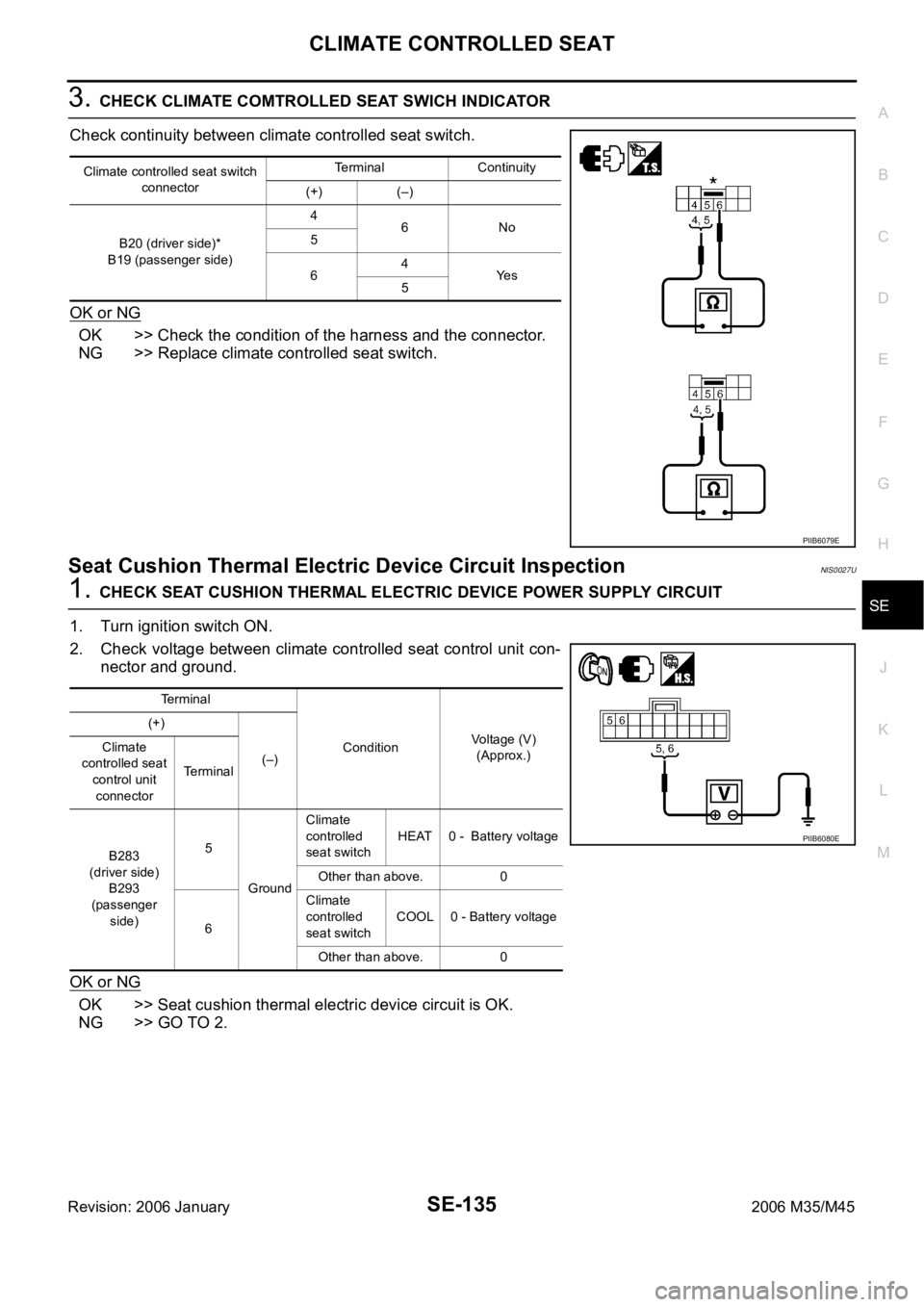
3. CHECK CLIMATE COMTROLLED SEAT SWICH INDICATOR
Check continuity between climate controlled seat switch.
OK or NG
OK >> Check the condition of the harness and the connector.
NG >> Replace climate controlled seat switch.
Seat Cushion Thermal Electric Device Circuit InspectionNIS0027U
1. CHECK SEAT CUSHION THERMAL ELECTRIC DEVICE POWER SUPPLY CIRCUIT
1. Turn ignition switch ON.
2. Check voltage between climate controlled seat control unit con-
nector and ground.
OK or NG
OK >> Seat cushion thermal electric device circuit is OK.
NG >> GO TO 2.
Climate controlled seat switch
connectorTerminal Continuity
(+) (–)
B20 (driver side)*
B19 (passenger side)4
6No
5
64
Ye s
5
PIIB6079E
Terminal
ConditionVoltage (V)
(Approx.) (+)
(–) Climate
controlled seat
control unit
connectorTerminal
B283
(driver side)
B293
(passenger
side)5
GroundClimate
controlled
seat switchHEAT 0 - Battery voltage
Other than above. 0
6Climate
controlled
seat switchCOOL 0 - Battery voltage
Other than above. 0
PIIB6080E
Page 5317 of 5621
SE-136
CLIMATE CONTROLLED SEAT
Revision: 2006 January2006 M35/M45
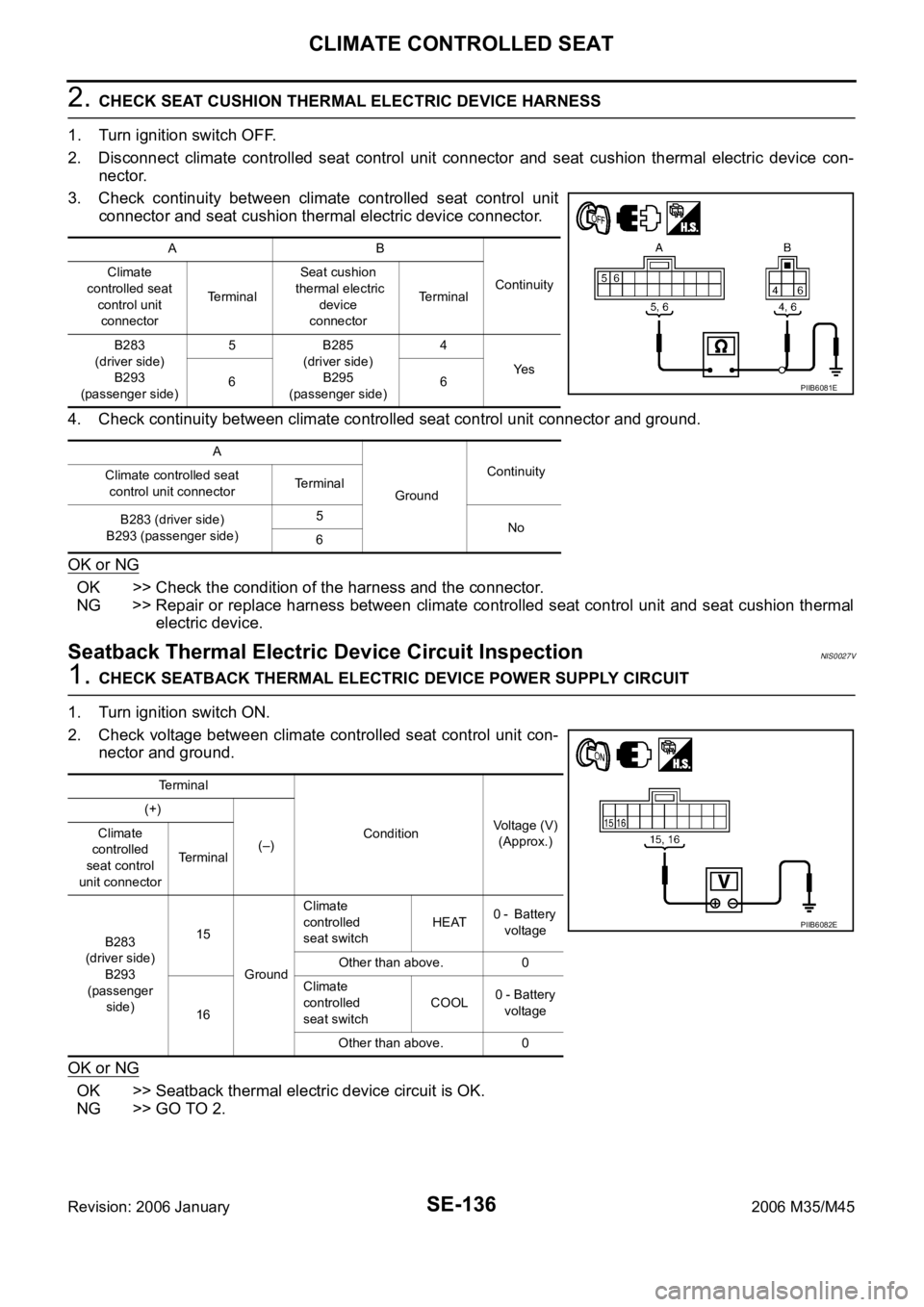
2. CHECK SEAT CUSHION THERMAL ELECTRIC DEVICE HARNESS
1. Turn ignition switch OFF.
2. Disconnect climate controlled seat control unit connector and seat cushion thermal electric device con-
nector.
3. Check continuity between climate controlled seat control unit
connector and seat cushion thermal electric device connector.
4. Check continuity between climate controlled seat control unit connector and ground.
OK or NG
OK >> Check the condition of the harness and the connector.
NG >> Repair or replace harness between climate controlled seat control unit and seat cushion thermal
electric device.
Seatback Thermal Electric Device Circuit InspectionNIS0027V
1. CHECK SEATBACK THERMAL ELECTRIC DEVICE POWER SUPPLY CIRCUIT
1. Turn ignition switch ON.
2. Check voltage between climate controlled seat control unit con-
nector and ground.
OK or NG
OK >> Seatback thermal electric device circuit is OK.
NG >> GO TO 2.
AB
Continuity Climate
controlled seat
control unit
connectorTe r m i n a lSeat cushion
thermal electric
device
connectorTerminal
B283
(driver side)
B293
(passenger side)5 B285
(driver side)
B295
(passenger side)4
Ye s
66
A
GroundContinuity
Climate controlled seat
control unit connectorTerminal
B283 (driver side)
B293 (passenger side)5
No
6
PIIB6081E
Te r m i n a l
ConditionVoltage (V)
(Approx.) (+)
(–) Climate
controlled
seat control
unit connectorTerminal
B283
(driver side)
B293
(passenger
side)15
GroundClimate
controlled
seat switchHEAT0 - Battery
voltage
Other than above. 0
16Climate
controlled
seat switchCOOL0 - Battery
voltage
Other than above. 0
PIIB6082E
Page 5318 of 5621
CLIMATE CONTROLLED SEAT
SE-137
C
D
E
F
G
H
J
K
L
MA
B
SE
Revision: 2006 January2006 M35/M45
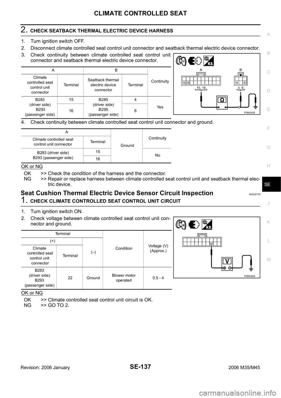
2. CHECK SEATBACK THERMAL ELECTRIC DEVICE HARNESS
1. Turn ignition switch OFF.
2. Disconnect climate controlled seat control unit connector and seatback thermal electric device connector.
3. Check continuity between climate controlled seat control unit
connector and seatback thermal electric device connector.
4. Check continuity between climate controlled seat control unit connector and ground.
OK or NG
OK >> Check the condition of the harness and the connector.
NG >> Repair or replace harness between climate controlled seat control unit and seatback thermal elec-
tric device.
Seat Cushion Thermal Electric Device Sensor Circuit InspectionNIS0027W
1. CHECK CLIMATE CONTROLLED SEAT CONTROL UNIT CIRCUIT
1. Turn ignition switch ON.
2. Check voltage between climate controlled seat control unit con-
nector and ground.
OK or NG
OK >> Climate controlled seat control unit circuit is OK.
NG >> GO TO 2.
AB
Continuity Climate
controlled seat
control unit
connectorTerminalSeatback thermal
electric device
connectorTerminal
B283
(driver side)
B293
(passenger side)15 B285
(driver side)
B295
(passenger side)4
Ye s
16 6
A
GroundContinuity
Climate controlled seat
control unit connectorTerminal
B283 (driver side)
B293 (passenger side)15
No
16
PIIB6083E
Terminal
ConditionVoltage (V)
(Approx.) (+)
(–) Climate
controlled seat
control unit
connectorTe r m i n a l
B283
(driver side)
B293
(passenger side)22 GroundBlower motor
operated0.5 - 4
PIIB6084E
Page 5319 of 5621

SE-138
CLIMATE CONTROLLED SEAT
Revision: 2006 January2006 M35/M45
2. CHECK SEAT CUSHION THERMAL ELECTRIC DEVICE SENSOR HARNESS
1. Turn ignition switch OFF.
2. Disconnect climate controlled seat control unit connector and seat cushion thermal electric device con-
nector.
3. Check continuity between climate controlled seat control unit
connector and seat cushion thermal electric device connector.
4. Check continuity between climate controlled seat control unit connector and ground.
OK or NG
OK >> GO TO 3.
NG >> Repair or replace harness between climate controlled seat control unit and seat cushion thermal
electric device.
3. CHECK SEAT CUSHION THERMAL ELECTRIC DEVICE SENSOR
Check resistance between seat cushion thermal electric device con-
nector.
OK or NG
OK >> Check the condition of the harness and the connector.
NG >> Replace seat cushion thermal electric device.
AB
Continuity Climate
controlled seat
control unit
connectorTe r m i n a lSeat cushion
thermal electric
device connectorTerminal
B283
(driver side)
B293
(passenger side)21 B285
(driver side)
B295
(passenger side)2
Ye s
22 1
A
GroundContinuity
Climate controlled seat
control unit connectorTerminal
B283 (driver side)
B293 (passenger side)21
No
22
PIIB6085E
Seat cushion thermal
electric device connectorTerminal Resistance (K)
(Approx.)
B220
(driver side)
B258
(passenger side)12 2
PIIB6086E
Page 5320 of 5621
CLIMATE CONTROLLED SEAT
SE-139
C
D
E
F
G
H
J
K
L
MA
B
SE
Revision: 2006 January2006 M35/M45
Seatback Thermal Electric Device Sensor Circuit InspectionNIS0027X
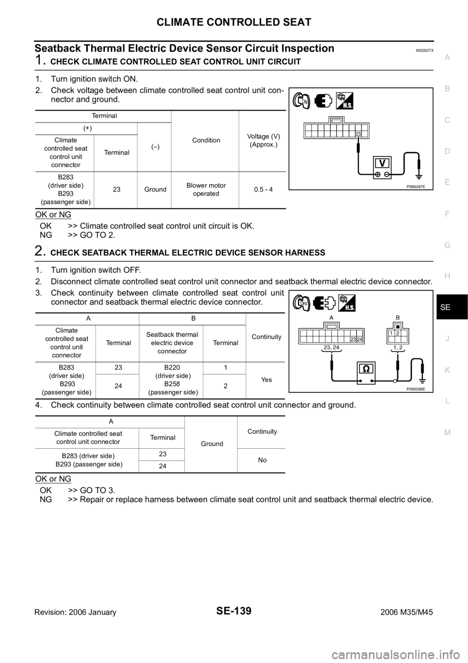
1. CHECK CLIMATE CONTROLLED SEAT CONTROL UNIT CIRCUIT
1. Turn ignition switch ON.
2. Check voltage between climate controlled seat control unit con-
nector and ground.
OK or NG
OK >> Climate controlled seat control unit circuit is OK.
NG >> GO TO 2.
2. CHECK SEATBACK THERMAL ELECTRIC DEVICE SENSOR HARNESS
1. Turn ignition switch OFF.
2. Disconnect climate controlled seat control unit connector and seatback thermal electric device connector.
3. Check continuity between climate controlled seat control unit
connector and seatback thermal electric device connector.
4. Check continuity between climate controlled seat control unit connector and ground.
OK or NG
OK >> GO TO 3.
NG >> Repair or replace harness between climate seat control unit and seatback thermal electric device.
Terminal
ConditionVoltage (V)
(Approx.) (+)
(–) Climate
controlled seat
control unit
connectorTe r m i n a l
B283
(driver side)
B293
(passenger side)23 GroundBlower motor
operated0.5 - 4
PIIB6087E
AB
Continuity Climate
controlled seat
control unit
connectorTerminalSeatback thermal
electric device
connectorTerminal
B283
(driver side)
B293
(passenger side)23 B220
(driver side)
B258
(passenger side)1
Ye s
24 2
A
GroundContinuity
Climate controlled seat
control unit connectorTerminal
B283 (driver side)
B293 (passenger side)23
No
24
PIIB6088E
Page 5321 of 5621
SE-140
CLIMATE CONTROLLED SEAT
Revision: 2006 January2006 M35/M45
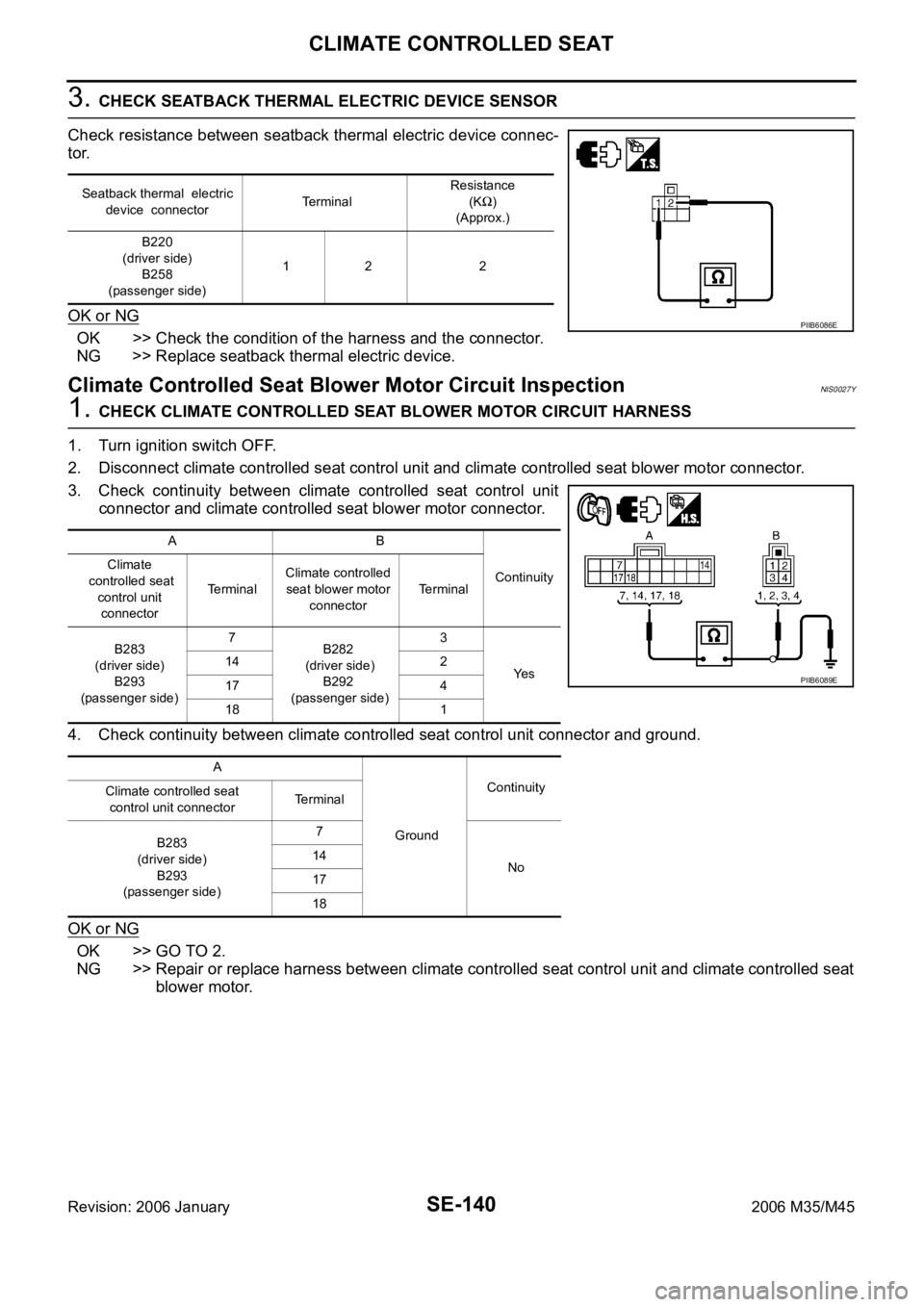
3. CHECK SEATBACK THERMAL ELECTRIC DEVICE SENSOR
Check resistance between seatback thermal electric device connec-
tor.
OK or NG
OK >> Check the condition of the harness and the connector.
NG >> Replace seatback thermal electric device.
Climate Controlled Seat Blower Motor Circuit InspectionNIS0027Y
1. CHECK CLIMATE CONTROLLED SEAT BLOWER MOTOR CIRCUIT HARNESS
1. Turn ignition switch OFF.
2. Disconnect climate controlled seat control unit and climate controlled seat blower motor connector.
3. Check continuity between climate controlled seat control unit
connector and climate controlled seat blower motor connector.
4. Check continuity between climate controlled seat control unit connector and ground.
OK or NG
OK >> GO TO 2.
NG >> Repair or replace harness between climate controlled seat control unit and climate controlled seat
blower motor.
Seatback thermal electric
device connectorTe r m i n a l Resistance
(K)
(Approx.)
B220
(driver side)
B258
(passenger side)12 2
PIIB6086E
AB
Continuity Climate
controlled seat
control unit
connectorTe r m i n a lClimate controlled
seat blower motor
connectorTerminal
B283
(driver side)
B293
(passenger side)7
B282
(driver side)
B292
(passenger side)3
Ye s 14 2
17 4
18 1
A
GroundContinuity
Climate controlled seat
control unit connectorTerminal
B283
(driver side)
B293
(passenger side)7
No 14
17
18
PIIB6089E
Page 5322 of 5621
CLIMATE CONTROLLED SEAT
SE-141
C
D
E
F
G
H
J
K
L
MA
B
SE
Revision: 2006 January2006 M35/M45
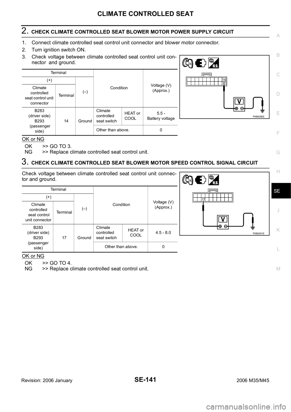
2. CHECK CLIMATE CONTROLLED SEAT BLOWER MOTOR POWER SUPPLY CIRCUIT
1. Connect climate controlled seat control unit connector and blower motor connector.
2. Turn ignition switch ON.
3. Check voltage between climate controlled seat control unit con-
nector and ground.
OK or NG
OK >> GO TO 3.
NG >> Replace climate controlled seat control unit.
3. CHECK CLIMATE CONTROLLED SEAT BLOWER MOTOR SPEED CONTROL SIGNAL CIRCUIT
Check voltage between climate controlled seat control unit connec-
tor and ground.
OK or NG
OK >> GO TO 4.
NG >> Replace climate controlled seat control unit.
Terminal
ConditionVoltage (V)
(Approx.) (+)
(–) Climate
controlled
seat control unit
connectorTerminal
B283
(driver side)
B293
(passenger
side)14 GroundClimate
controlled
seat switchHEAT or
COOL5.5 -
Battery voltage
Other than above. 0
PIIB6090E
Terminal
ConditionVoltage (V)
(Approx.) (+)
(–) Climate
controlled
seat control
unit connectorTerminal
B283
(driver side)
B293
(passenger
side)17 GroundClimate
controlled
seat switchHEAT or
COOL4.5 - 8.0
Other than above. 0
PIIB6091E
Page 5324 of 5621
HEATED SEAT
SE-143
C
D
E
F
G
H
J
K
L
MA
B
SE
Revision: 2006 January2006 M35/M45
HEATED SEATPFP:87335
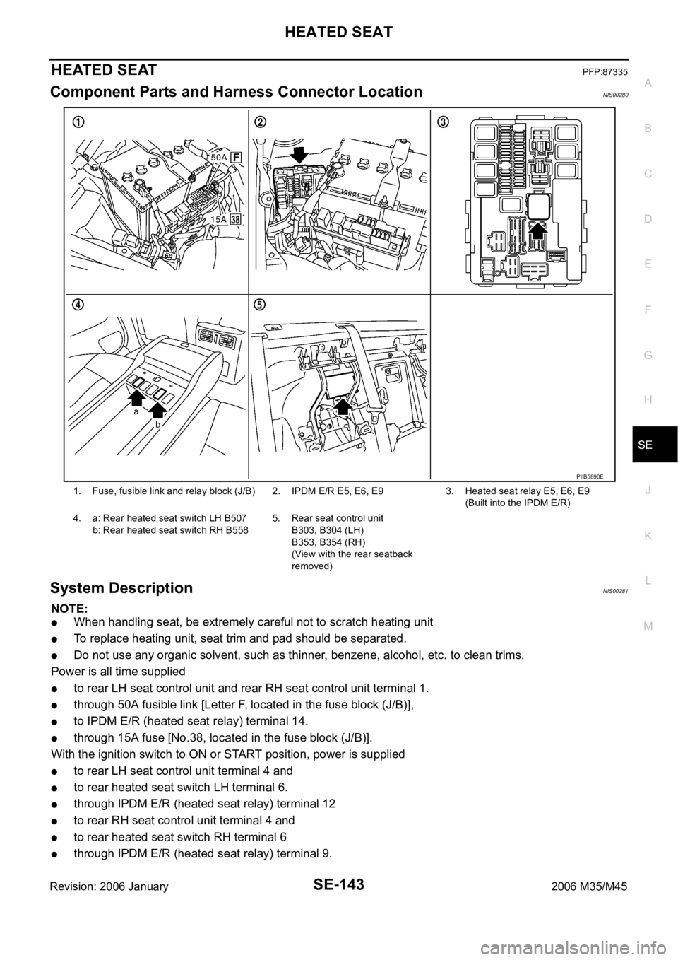
Component Parts and Harness Connector LocationNIS00280
System Description NIS00281
NOTE:
When handling seat, be extremely careful not to scratch heating unit
To replace heating unit, seat trim and pad should be separated.
Do not use any organic solvent, such as thinner, benzene, alcohol, etc. to clean trims.
Power is all time supplied
to rear LH seat control unit and rear RH seat control unit terminal 1.
through 50A fusible link [Letter F, located in the fuse block (J/B)],
to IPDM E/R (heated seat relay) terminal 14.
through 15A fuse [No.38, located in the fuse block (J/B)].
With the ignition switch to ON or START position, power is supplied
to rear LH seat control unit terminal 4 and
to rear heated seat switch LH terminal 6.
through IPDM E/R (heated seat relay) terminal 12
to rear RH seat control unit terminal 4 and
to rear heated seat switch RH terminal 6
through IPDM E/R (heated seat relay) terminal 9.
1. Fuse, fusible link and relay block (J/B) 2. IPDM E/R E5, E6, E93. Heated seat relay E5, E6, E9
(Built into the IPDM E/R)
4. a: Rear heated seat switch LH B507
b: Rear heated seat switch RH B5585. Rear seat control unit
B303, B304 (LH)
B353, B354 (RH)
(View with the rear seatback
removed)
PIIB5890E