Page 5245 of 5621
SE-64
AUTOMATIC DRIVE POSITIONER
Revision: 2006 January2006 M35/M45
2. CHECK DOOR MIRROR LH SENSOR
With CONSULT–II
Check that “VOLTAGE” is displayed on “MIR/SE LH R–L, MIR/SE LH U–D" in the DATA MONITOR.
Without CONSULT–II
1. Turn ignition switch to ACC.
2. Check voltage between automatic drive positioner control unit connector and ground.
OK or NG
OK >> Mirror sensor LH circuit is OK.
NG >> GO TO 3.
Monitor item [OPERATION or
UNIT]Contents
MIR/
SEN LH R–L“V”Voltage output from door mirror LH sensor (LH/
RH) is displayed.
MIR/
SEN LH U–D“V”Voltage output from door mirror LH sensor (UP/
DOWN) is displayed.
PIIB6495E
Automatic
drive posi-
tioner con-
trol unit
connectorTerminals
ConditionVoltage (V)
(Approx.)
(+) (–)
M622
GroundMirror motor is
operated LEFT or
RIGHTChanges between
3.5 (close to right edge) –
0.5 (close to left edge)
6Mirror motor is
operated UP or
DOWN Changes between
4.2 (close to peak) –
0.5 (close to valley)
PIIB6163E
Page 5246 of 5621

AUTOMATIC DRIVE POSITIONER
SE-65
C
D
E
F
G
H
J
K
L
MA
B
SE
Revision: 2006 January2006 M35/M45
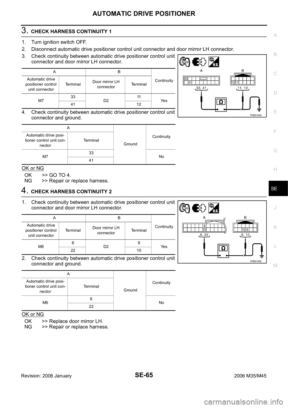
3. CHECK HARNESS CONTINUITY 1
1. Turn ignition switch OFF.
2. Disconnect automatic drive positioner control unit connector and door mirror LH connector.
3. Check continuity between automatic drive positioner control unit
connector and door mirror LH connector.
4. Check continuity between automatic drive positioner control unit
connector and ground.
OK or NG
OK >> GO TO 4.
NG >> Repair or replace harness.
4. CHECK HARNESS CONTINUITY 2
1. Check continuity between automatic drive positioner control unit
connector and door mirror LH connector.
2. Check continuity between automatic drive positioner control unit
connector and ground.
OK or NG
OK >> Replace door mirror LH.
NG >> Repair or replace harness.
AB
Continuity Automatic drive
positioner control
unit connectorTerminalDoor mirror LH
connectorTerminal
M733
D211
Ye s
41 12
A
GroundContinuity Automatic drive posi-
tioner control unit con-
nectorTerminal
M733
No
41
PIIB6164E
AB
Continuity Automatic drive
positioner control
unit connectorTerminalDoor mirror LH
connectorTerminal
M66
D29
Ye s
22 10
A
GroundContinuity Automatic drive posi-
tioner control unit con-
nectorTerminal
M66
No
22
PIIB6165E
Page 5247 of 5621

SE-66
AUTOMATIC DRIVE POSITIONER
Revision: 2006 January2006 M35/M45
Door Mirror Sensor RH Circuit Check NIS0026K
1. CHECK DOOR MIRROR FUNCTION
Check the following items.
Operation malfunction in memory operation.
NOTE:
If a door mirror face position is set to an implausible angle, the set position may not be reproduced.
OK or NG
OK >> GO TO 2.
NG >> Repair or replace the malfunctioning parts, and check the symptom again.
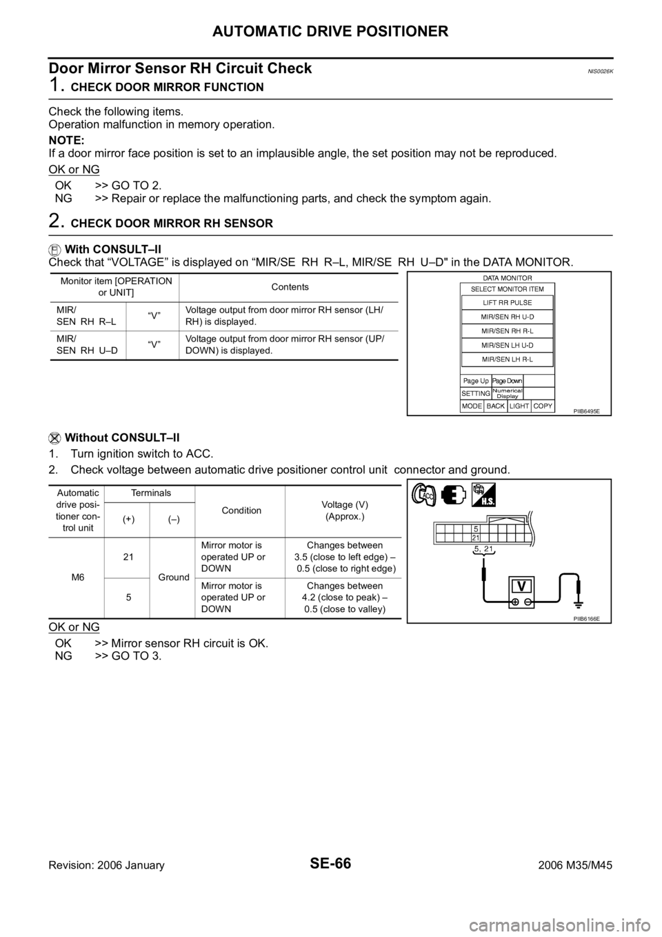
2. CHECK DOOR MIRROR RH SENSOR
With CONSULT–II
Check that “VOLTAGE” is displayed on “MIR/SE RH R–L, MIR/SE RH U–D" in the DATA MONITOR.
Without CONSULT–II
1. Turn ignition switch to ACC.
2. Check voltage between automatic drive positioner control unit connector and ground.
OK or NG
OK >> Mirror sensor RH circuit is OK.
NG >> GO TO 3.
Monitor item [OPERATION
or UNIT]Contents
MIR/
SEN RH R–L“V”Voltage output from door mirror RH sensor (LH/
RH) is displayed.
MIR/
SEN RH U–D“V”Voltage output from door mirror RH sensor (UP/
DOWN) is displayed.
PIIB6495E
Automatic
drive posi-
tioner con-
trol unitTerminals
ConditionVoltage (V)
(Approx.)
(+) (–)
M621
GroundMirror motor is
operated UP or
DOWNChanges between
3.5 (close to left edge) –
0.5 (close to right edge)
5Mirror motor is
operated UP or
DOWN Changes between
4.2 (close to peak) –
0.5 (close to valley)
PIIB6166E
Page 5248 of 5621

AUTOMATIC DRIVE POSITIONER
SE-67
C
D
E
F
G
H
J
K
L
MA
B
SE
Revision: 2006 January2006 M35/M45
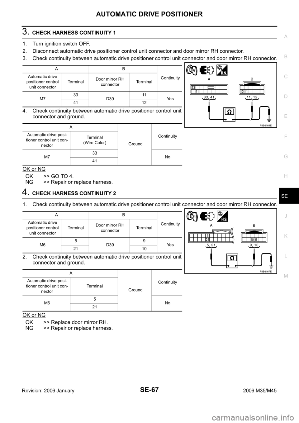
3. CHECK HARNESS CONTINUITY 1
1. Turn ignition switch OFF.
2. Disconnect automatic drive positioner control unit connector and door mirror RH connector.
3. Check continuity between automatic drive positioner control unit connector and door mirror RH connector.
4. Check continuity between automatic drive positioner control unit
connector and ground.
OK or NG
OK >> GO TO 4.
NG >> Repair or replace harness.
4. CHECK HARNESS CONTINUITY 2
1. Check continuity between automatic drive positioner control unit connector and door mirror RH connector.
2. Check continuity between automatic drive positioner control unit
connector and ground.
OK or NG
OK >> Replace door mirror RH.
NG >> Repair or replace harness.
AB
Continuity Automatic drive
positioner control
unit connectorTerminalDoor mirror RH
connectorTerminal
M733
D3911
Ye s
41 12
A
GroundContinuity Automatic drive posi-
tioner control unit con-
nectorTerminal
(Wire Color)
M733
No
41
PIIB6164E
AB
Continuity Automatic drive
positioner control
unit connectorTerminalDoor mirror RH
connectorTerminal
M65
D399
Ye s
21 10
A
GroundContinuity Automatic drive posi-
tioner control unit con-
nectorTerminal
M65
No
21
PIIB6167E
Page 5249 of 5621
SE-68
AUTOMATIC DRIVE POSITIONER
Revision: 2006 January2006 M35/M45
Sliding Switch Circuit CheckNIS0026L
1. CHECK FUNCTION
With CONSULT-II
With “SLIDE SW-FR, SLIDE SW-RR” on the DATA MONITOR, oper-
ate the sliding switch to check ON/OFF operation.
Without CONSULT-II
1. Turn ignition switch OFF.
2. Check voltage between driver seat control unit connector and
ground.
OK or NG
OK >> Sliding switch circuit is OK.
NG >> GO TO 2.
Monitor item [OPER-
ATION or UNIT]Contents
SLIDE SW–
FR"ON/
OFF"ON / OFF status judged from the sliding switch (FR) sig-
nal is displayed.
SLIDE SW–
RR"ON/
OFF"ON / OFF status judged from the sliding switch (RR) sig-
nal is displayed.
PIIA0313E
Driver seat
control unit
connectorTerminal
ConditionVoltage (V)
(Approx.)
(+) (–)
B20411
GroundSliding switch ON
(BACKWARD oper-
ation)0
Other than above Battery voltage
26Sliding switch ON
(FORWARD opera-
tion)0
Other than above Battery voltage
PIIB6168E
Page 5251 of 5621
SE-70
AUTOMATIC DRIVE POSITIONER
Revision: 2006 January2006 M35/M45
Reclining Switch Circuit CheckNIS0026M
1. CHECK FUNCTION
With CONSULT-II
With “RECLN SW-FR, RECLN SW-RR” on the DATA MONITOR,
operate the reclining switch to check ON/OFF operation.
Without CONSULT-II
1. Turn ignition switch OFF.
2. Check voltage between driver seat control unit connector and
ground.
OK or NG
OK >> Reclining switch circuit is OK.
NG >> GO TO 2.
Monitor item [OPERA-
TION or UNIT]Contents
RECLN SW
–FR“ON/
OFF”ON/OFF status judged from the reclining switch (FR)
signal is displayed.
RECLIN S
W–RR“ON/
OFF”ON/OFF status judged from the reclining switch (RR)
signal is displayed.
PIIA0313E
Driver seat
control unitTe r m i n a l s
ConditionVoltage (V)
(Approx.)
(+) (–)
B20412
GroundReclining switch ON
(BACKWARD oper-
ation)0
Other than above Battery voltage
27Reclining switch ON
(FORWARD opera-
tion)0
Other than above Battery voltage
PIIB6171E
Page 5253 of 5621
SE-72
AUTOMATIC DRIVE POSITIONER
Revision: 2006 January2006 M35/M45
Lifting Switch (Front) Circuit CheckNIS0026N
1. CHECK FUNCTION
With CONSULT-II
With “LIFT FR SW-UP, LIFT FR SW-DN” on the DATA MONITOR,
operate the lifting switch (front) to check ON/OFF operation.
Without CONSULT-II
1. Turn ignition switch OFF.
2. Check voltage between driver seat control unit connector and
ground.
OK or NG
OK >> Lifting switch (front) circuit is OK.
NG >> GO TO 2.
Monitor item [OPERA-
TION or UNIT]Contents
LIFT FR SW–
DN"ON/
OFF"ON / OFF status judged from the FR lifter switch
(DOWN) signal is displayed.
LIFT FR SW–
UP"ON/
OFF"ON / OFF status judged from the FR lifter switch (UP)
signal is displayed.
PIIA0323E
Driver seat
control unit
connectorTerminals
ConditionVoltage (V)
(Approx.)
(+) (–)
B20413
GroundLifting switch (front) ON
(DOWN operation)0
Other than above Battery voltage
28Lifting switch (front) ON
(UP operation)0
Other than above Battery voltage
PIIB6174E
Page 5255 of 5621

SE-74
AUTOMATIC DRIVE POSITIONER
Revision: 2006 January2006 M35/M45
Lifting Switch (Rear) Circuit CheckNIS0026O
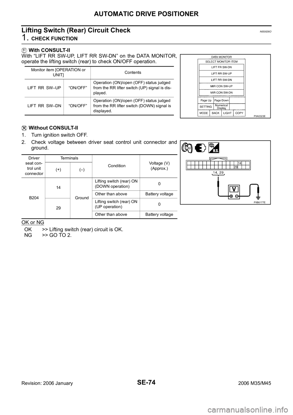
1. CHECK FUNCTION
With CONSULT-II
With “LIFT RR SW-UP, LIFT RR SW-DN” on the DATA MONITOR,
operate the lifting switch (rear) to check ON/OFF operation.
Without CONSULT-II
1. Turn ignition switch OFF.
2. Check voltage between driver seat control unit connector and
ground.
OK or NG
OK >> Lifting switch (rear) circuit is OK.
NG >> GO TO 2.
Monitor item [OPERATION or
UNIT]Contents
LIFT RR SW–UP “ON/OFF”Operation (ON)/open (OFF) status judged
from the RR lifter switch (UP) signal is dis-
played.
LIFT RR SW–DN “ON/OFF”Operation (ON)/open (OFF) status judged
from the RR lifter switch (DOWN) signal is
displayed.
PIIA0323E
Driver
seat con-
trol unit
connectorTerminals
ConditionVoltage (V)
(Approx.)
(+) (–)
B20414
GroundLifting switch (rear) ON
(DOWN operation)0
Other than above Battery voltage
29Lifting switch (rear) ON
(UP operation)0
Other than above Battery voltage
PIIB6177E