Page 1112 of 5621
INTELLIGENT KEY SYSTEM/ENGINE START FUNCTION
BL-173
C
D
E
F
G
H
J
K
L
MA
B
BL
Revision: 2006 January2006 M35/M45
2. CHECK HARNESS CONTINUITY 1
1. Turn ignition switch OFF.
2. Disconnect Intelligent Key unit and A/T device connector.
3. Check continuity between Intelligent Key unit connector and A/T device connector.
4. Check continuity between Intelligent Key unit connector and
ground.
OK or NG
OK >> GO TO 3.
NG >> Repair or replace harness.
3. CHECK A/T DEVICE
Check A/T device.
OK or NG
OK >> Check the condition of harness and connector. If it is
OK, check the self-diagnosis results using CONSULT-II
again.
NG >> Replace A/T device.
AB
Continuity
Intelligent Key
unit connectorTerminalA/T device
connectorTerminal
M32 27
M13310
Ye s
M33 58 9
A
GroundContinuity
Intelligent Key unit connector Terminal
M32 27
No
M33 58
PIIB6245E
Terminal
A/T control device
positionContinuity
A/T device
910PYes
Other than above No
PIIB6246E
Page 1113 of 5621
BL-174
INTELLIGENT KEY SYSTEM/ENGINE START FUNCTION
Revision: 2006 January2006 M35/M45
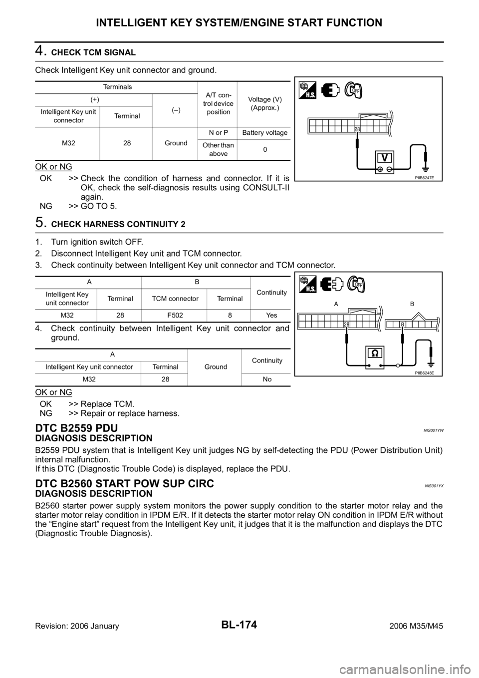
4. CHECK TCM SIGNAL
Check Intelligent Key unit connector and ground.
OK or NG
OK >> Check the condition of harness and connector. If it is
OK, check the self-diagnosis results using CONSULT-II
again.
NG >> GO TO 5.
5. CHECK HARNESS CONTINUITY 2
1. Turn ignition switch OFF.
2. Disconnect Intelligent Key unit and TCM connector.
3. Check continuity between Intelligent Key unit connector and TCM connector.
4. Check continuity between Intelligent Key unit connector and
ground.
OK or NG
OK >> Replace TCM.
NG >> Repair or replace harness.
DTC B2559 PDUNIS001YW
DIAGNOSIS DESCRIPTION
B2559 PDU system that is Intelligent Key unit judges NG by self-detecting the PDU (Power Distribution Unit)
internal malfunction.
If this DTC (Diagnostic Trouble Code) is displayed, replace the PDU.
DTC B2560 START POW SUP CIRCNIS001YX
DIAGNOSIS DESCRIPTION
B2560 starter power supply system monitors the power supply condition to the starter motor relay and the
starter motor relay condition in IPDM E/R. If it detects the starter motor relay ON condition in IPDM E/R without
the “Engine start” request from the Intelligent Key unit, it judges that it is the malfunction and displays the DTC
(Diagnostic Trouble Diagnosis).
Terminals
A/T con-
trol device
positionVoltage (V)
(Approx.) (+)
(–)
Intelligent Key unit
connectorTerminal
M32 28 GroundN or P Battery voltage
Other than
above0
PIIB6247E
AB
Continuity
Intelligent Key
unit connectorTerminal TCM connector Terminal
M32 28 F502 8 Yes
A
GroundContinuity
Intelligent Key unit connector Terminal
M32 28 No
PIIB6248E
Page 1114 of 5621

INTELLIGENT KEY SYSTEM/ENGINE START FUNCTION
BL-175
C
D
E
F
G
H
J
K
L
MA
B
BL
Revision: 2006 January2006 M35/M45
TERMINALS AND REFERENCE VALUE
Intelligent Key Unit
PDU (Power Distribution Unit)
SELF-DIAGNOSTIC LOGIC
DIAGNOSTIC PROCEDURE
1. CHECK HARNESS CONTINUITY 1
1. Turn ignition switch OFF.
2. Disconnect Intelligent Key unit and power distribution unit connector.
3. Check continuity between Intelligent Key unit connector and power distribution unit connector.
4. Check continuity between Intelligent Key unit connector and
ground.
OK or NG
OK >> GO TO 2.
NG >> Repair or replace harness.
Te r m i -
nal
No.Wire
colorItemCondition
Voltage (V)
(Approx.) Push-
button
ignition
switch
positionOperation or conditions
3YIPDM E/R current sig-
nalSTART At starter motor cranking 5
LOCK Any condition other than above 2
Te r -
minal
No.Wire
colorItemCondition
Voltage (V)
(Approx.) Push-
button
ignition
switch
positionOperation or conditions
13 R Starter relaySTART At starter motor cranking Battery voltage
— Any condition other than above 4
DTC Self-diagnosis name DTC detecting condition Possible causes
B2560START POW SUP
CIRCIt is detected that the power is supplied to the
starter motor without the engine start request from
the Intelligent Key unit
Harness and connector
(Open in the circuit between
the units)
PDU
IPDM E/R
AB
Continuity
Intelligent Key
unit connectorTerminalPower distribution
unit connectorTerminal
M32 3 M30 11 Yes
A
GroundContinuity
Intelligent Key unit connector Terminal
M32 3 No
PIIB6249E
Page 1121 of 5621
BL-182
INTELLIGENT KEY SYSTEM/ENGINE START FUNCTION
Revision: 2006 January2006 M35/M45
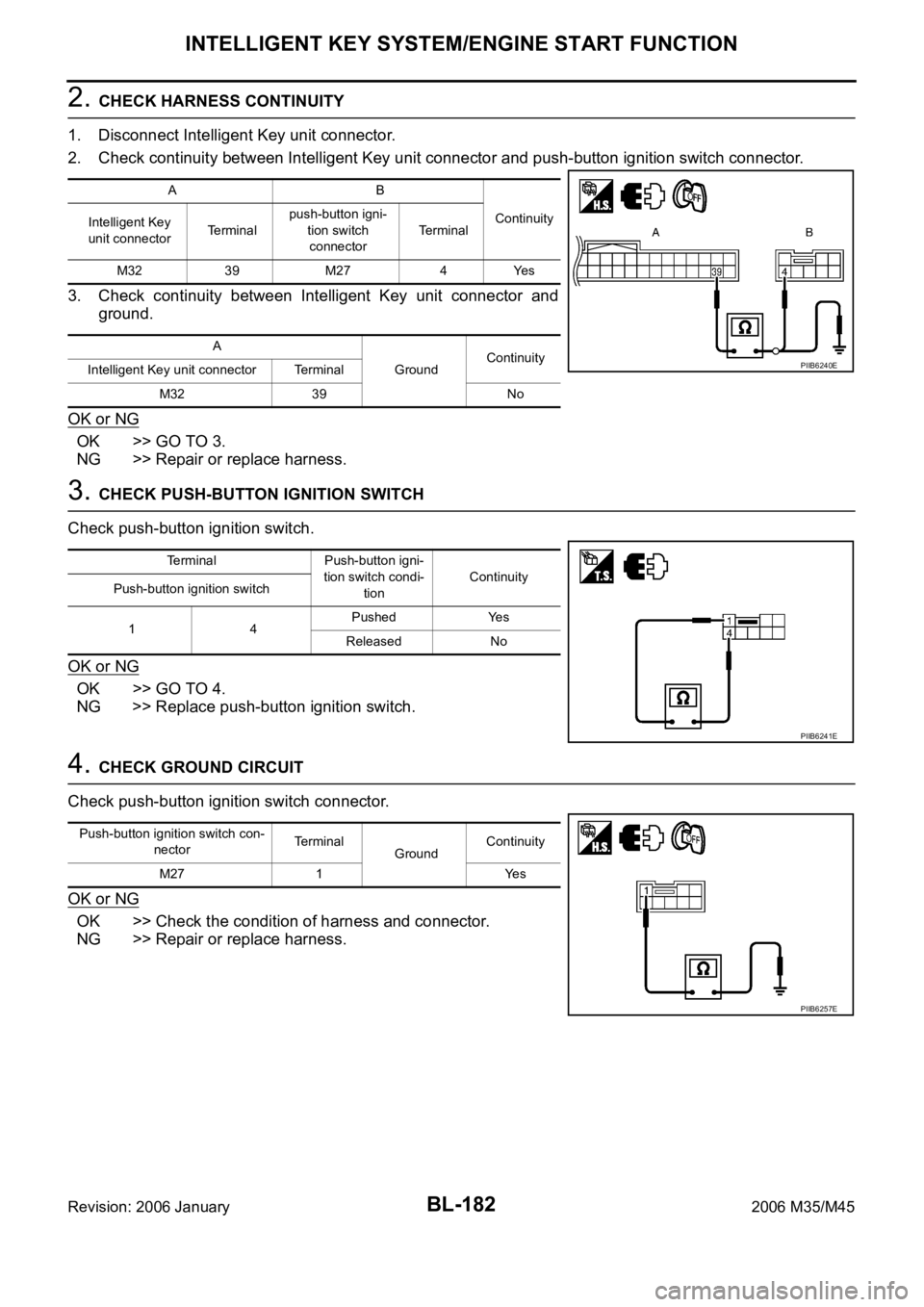
2. CHECK HARNESS CONTINUITY
1. Disconnect Intelligent Key unit connector.
2. Check continuity between Intelligent Key unit connector and push-button ignition switch connector.
3. Check continuity between Intelligent Key unit connector and
ground.
OK or NG
OK >> GO TO 3.
NG >> Repair or replace harness.
3. CHECK PUSH-BUTTON IGNITION SWITCH
Check push-button ignition switch.
OK or NG
OK >> GO TO 4.
NG >> Replace push-button ignition switch.
4. CHECK GROUND CIRCUIT
Check push-button ignition switch connector.
OK or NG
OK >> Check the condition of harness and connector.
NG >> Repair or replace harness.
AB
Continuity
Intelligent Key
unit connectorTe r m i n a lpush-button igni-
tion switch
connectorTerminal
M32 39 M27 4 Yes
A
GroundContinuity
Intelligent Key unit connector Terminal
M32 39 No
PIIB6240E
Terminal Push-button igni-
tion switch condi-
tionContinuity
Push-button ignition switch
14Pushed Yes
Released No
PIIB6241E
Push-button ignition switch con-
nectorTerminal
GroundContinuity
M27 1 Yes
PIIB6257E
Page 1126 of 5621
INTELLIGENT KEY SYSTEM/ENGINE START FUNCTION
BL-187
C
D
E
F
G
H
J
K
L
MA
B
BL
Revision: 2006 January2006 M35/M45
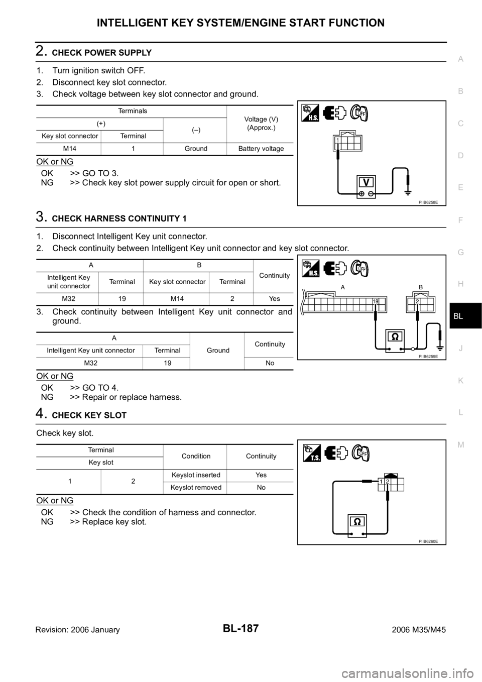
2. CHECK POWER SUPPLY
1. Turn ignition switch OFF.
2. Disconnect key slot connector.
3. Check voltage between key slot connector and ground.
OK or NG
OK >> GO TO 3.
NG >> Check key slot power supply circuit for open or short.
3. CHECK HARNESS CONTINUITY 1
1. Disconnect Intelligent Key unit connector.
2. Check continuity between Intelligent Key unit connector and key slot connector.
3. Check continuity between Intelligent Key unit connector and
ground.
OK or NG
OK >> GO TO 4.
NG >> Repair or replace harness.
4. CHECK KEY SLOT
Check key slot.
OK or NG
OK >> Check the condition of harness and connector.
NG >> Replace key slot.
Terminals
Voltage (V)
(Approx.) (+)
(–)
Key slot connector Terminal
M14 1 Ground Battery voltage
PIIB6258E
AB
Continuity
Intelligent Key
unit connectorTerminal Key slot connector Terminal
M32 19 M14 2 Yes
A
GroundContinuity
Intelligent Key unit connector Terminal
M32 19 No
PIIB6259E
Terminal
Condition Continuity
Key slot
12Keyslot inserted Yes
Keyslot removed No
PIIB6260E
Page 1128 of 5621
INTELLIGENT KEY SYSTEM/ENGINE START FUNCTION
BL-189
C
D
E
F
G
H
J
K
L
MA
B
BL
Revision: 2006 January2006 M35/M45
3. CHECK KEY SLOT SIGNAL
1. Connect key slot connector.
2. Check voltage between key slot connector and ground.
OK or NG
OK >> Check the condition of harness and connector.
NG >> Repair or replace harness between BCM and key slot.
Terminals
ConditionVoltage (V)
(Approx.) (+)
(–)
Key slot
connectorTerminal
M146
GroundCheck the voltage just
after the Intelligent Key
is inserted into the key
slot and the ignition
switch is turned to
START.The pointer of
the analog
tester fluctu-
ates. 7
PIIB6263E
Page 1156 of 5621
TRUNK LID OPENER
BL-217
C
D
E
F
G
H
J
K
L
MA
B
BL
Revision: 2006 January2006 M35/M45
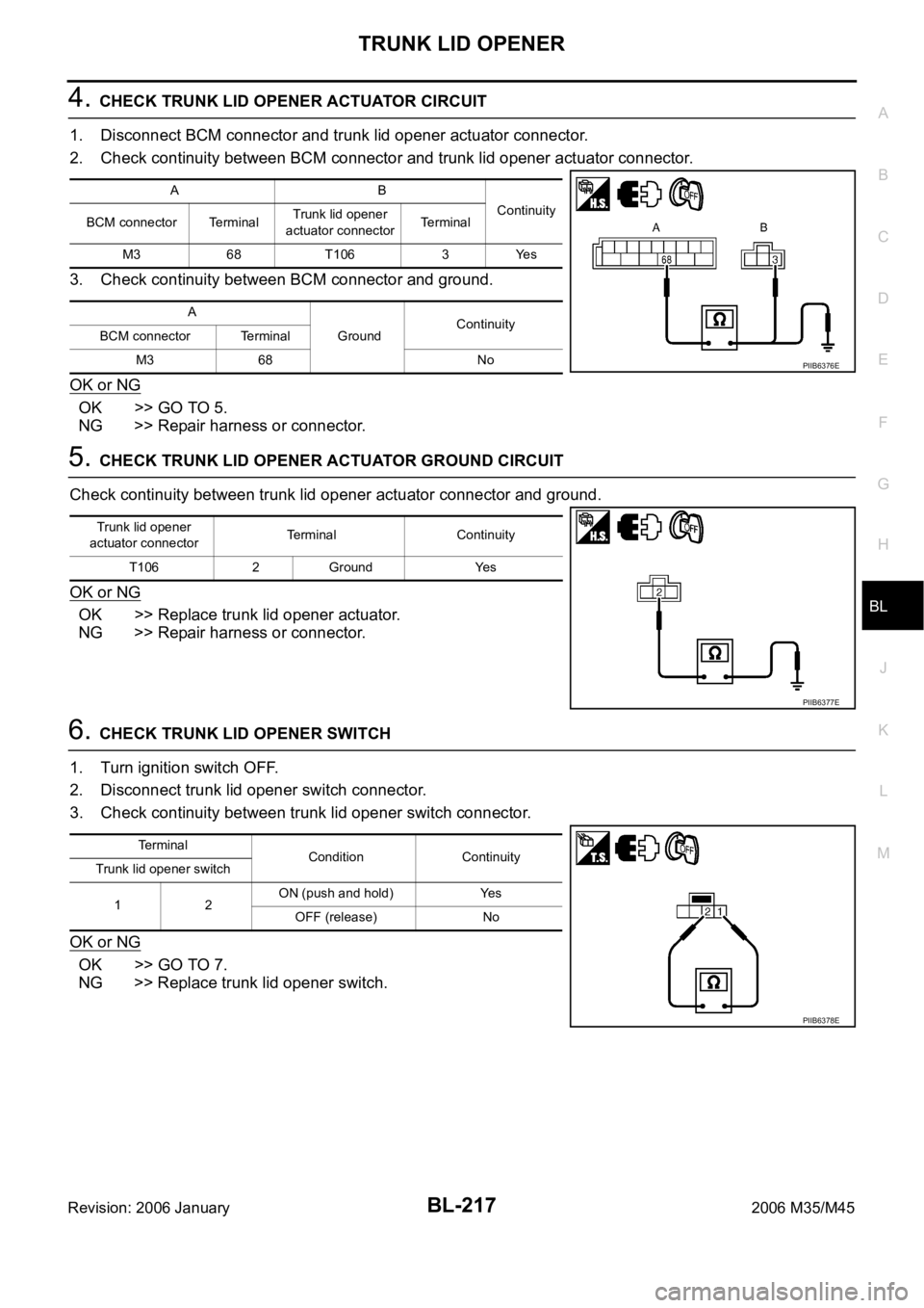
4. CHECK TRUNK LID OPENER ACTUATOR CIRCUIT
1. Disconnect BCM connector and trunk lid opener actuator connector.
2. Check continuity between BCM connector and trunk lid opener actuator connector.
3. Check continuity between BCM connector and ground.
OK or NG
OK >> GO TO 5.
NG >> Repair harness or connector.
5. CHECK TRUNK LID OPENER ACTUATOR GROUND CIRCUIT
Check continuity between trunk lid opener actuator connector and ground.
OK or NG
OK >> Replace trunk lid opener actuator.
NG >> Repair harness or connector.
6. CHECK TRUNK LID OPENER SWITCH
1. Turn ignition switch OFF.
2. Disconnect trunk lid opener switch connector.
3. Check continuity between trunk lid opener switch connector.
OK or NG
OK >> GO TO 7.
NG >> Replace trunk lid opener switch.
AB
Continuity
BCM connector TerminalTrunk lid opener
actuator connectorTerminal
M3 68 T106 3 Yes
A
GroundContinuity
BCM connector Terminal
M3 68 No
PIIB6376E
Trunk lid opener
actuator connectorTerminal Continuity
T106 2 Ground Yes
PIIB6377E
Te r m i n a l
Condition Continuity
Trunk lid opener switch
12ON (push and hold) Yes
OFF (release) No
PIIB6378E
Page 1157 of 5621
BL-218
TRUNK LID OPENER
Revision: 2006 January2006 M35/M45
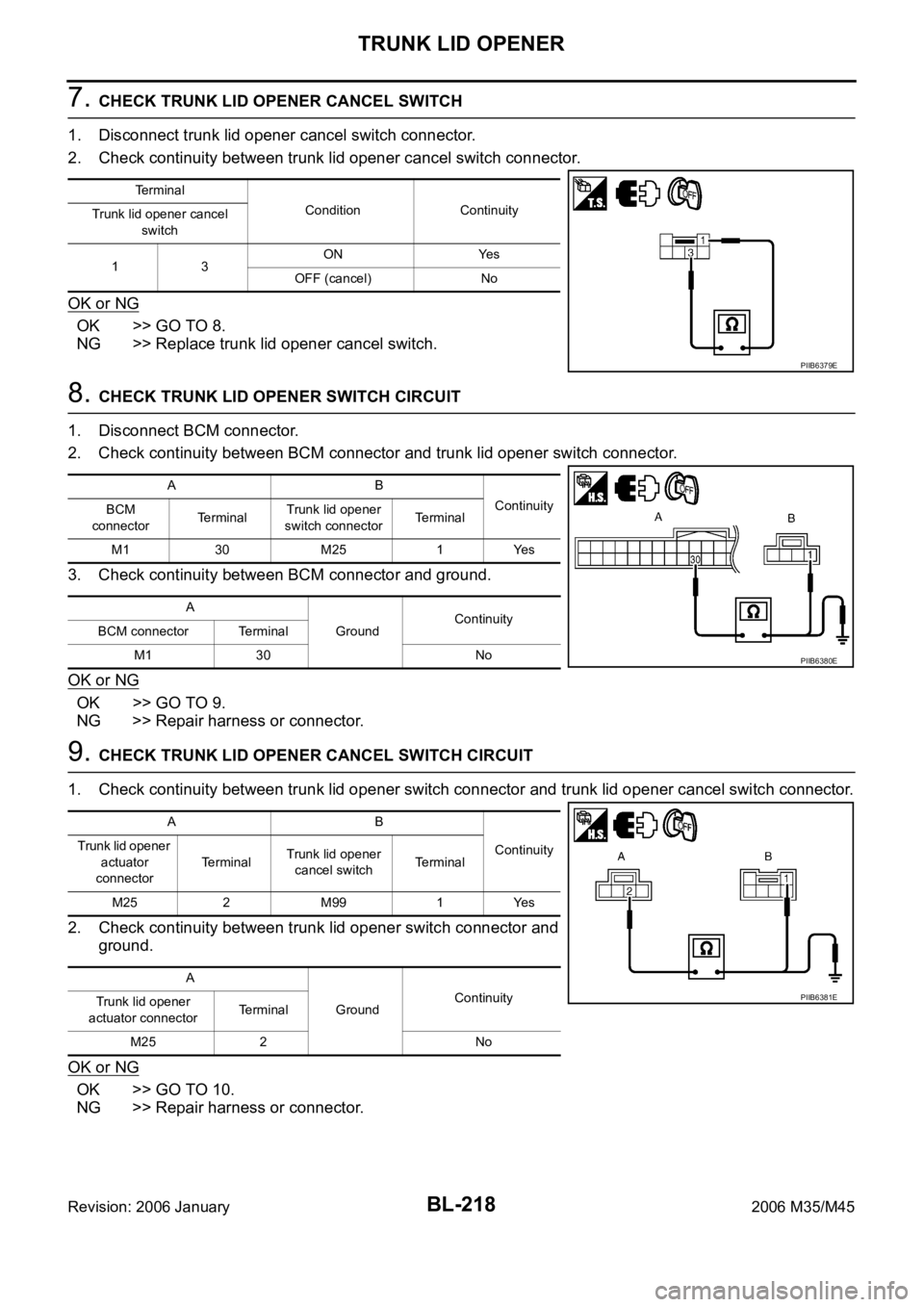
7. CHECK TRUNK LID OPENER CANCEL SWITCH
1. Disconnect trunk lid opener cancel switch connector.
2. Check continuity between trunk lid opener cancel switch connector.
OK or NG
OK >> GO TO 8.
NG >> Replace trunk lid opener cancel switch.
8. CHECK TRUNK LID OPENER SWITCH CIRCUIT
1. Disconnect BCM connector.
2. Check continuity between BCM connector and trunk lid opener switch connector.
3. Check continuity between BCM connector and ground.
OK or NG
OK >> GO TO 9.
NG >> Repair harness or connector.
9. CHECK TRUNK LID OPENER CANCEL SWITCH CIRCUIT
1. Check continuity between trunk lid opener switch connector and trunk lid opener cancel switch connector.
2. Check continuity between trunk lid opener switch connector and
ground.
OK or NG
OK >> GO TO 10.
NG >> Repair harness or connector.
Terminal
Condition Continuity
Trunk lid opener cancel
switch
13ON Yes
OFF (cancel) No
PIIB6379E
AB
Continuity
BCM
connectorTerminalTrunk lid opener
switch connectorTerminal
M1 30 M25 1 Yes
A
GroundContinuity
BCM connector Terminal
M1 30 No
PIIB6380E
AB
Continuity Trunk lid opener
actuator
connectorTerminalTrunk lid opener
cancel switchTerminal
M25 2 M99 1 Yes
A
GroundContinuity
Trunk lid opener
actuator connectorTerminal
M25 2 No
PIIB6381E