2006 INFINITI M35 air condition
[x] Cancel search: air conditionPage 1158 of 5621
TRUNK LID OPENER
BL-219
C
D
E
F
G
H
J
K
L
MA
B
BL
Revision: 2006 January2006 M35/M45
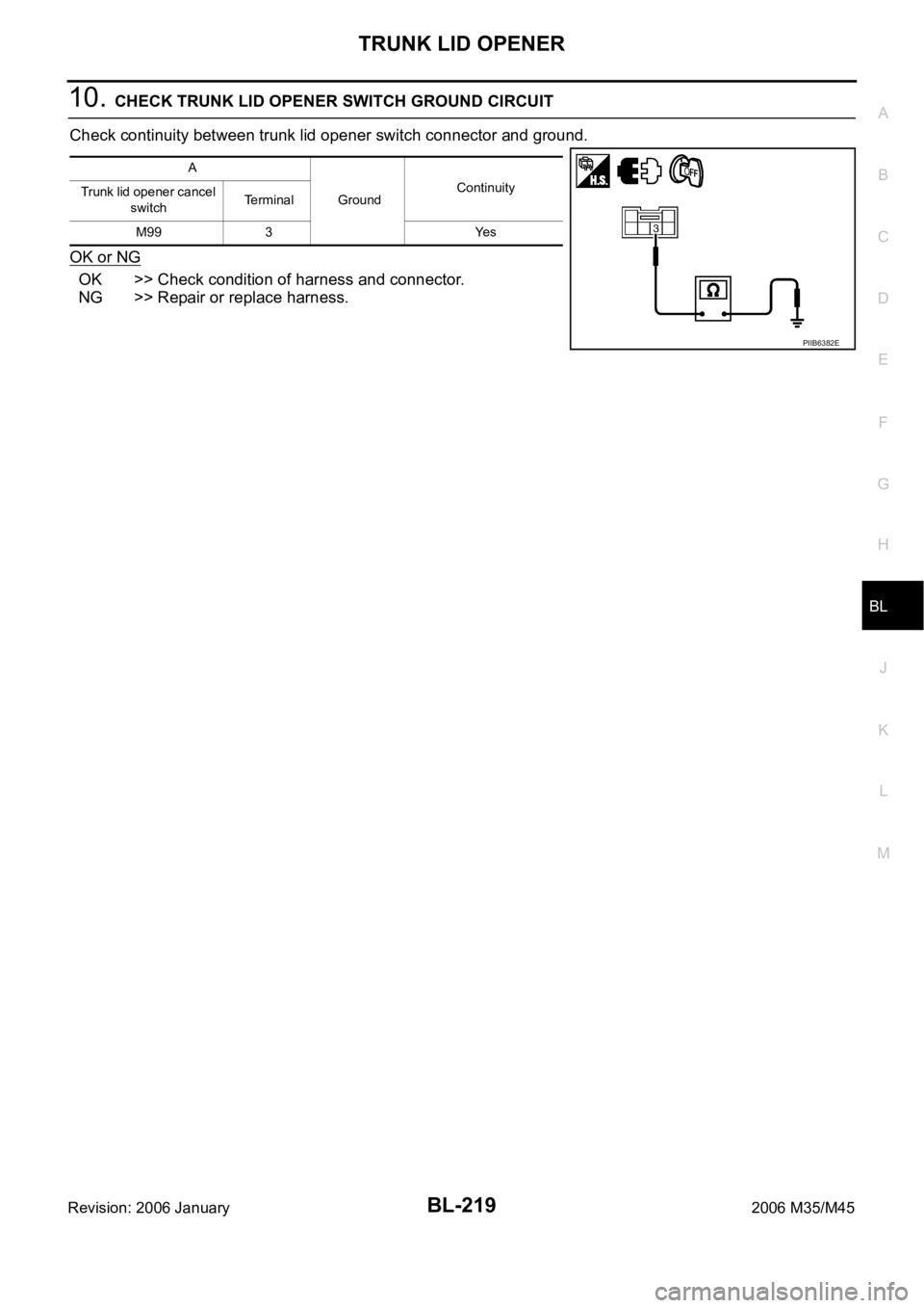
10. CHECK TRUNK LID OPENER SWITCH GROUND CIRCUIT
Check continuity between trunk lid opener switch connector and ground.
OK or NG
OK >> Check condition of harness and connector.
NG >> Repair or replace harness.
A
GroundContinuity
Trunk lid opener cancel
switchTerminal
M99 3 Yes
PIIB6382E
Page 1174 of 5621
VEHICLE SECURITY (THEFT WARNING) SYSTEM
BL-235
C
D
E
F
G
H
J
K
L
MA
B
BL
Revision: 2006 January2006 M35/M45
Active Test
Trouble Diagnosis Work FlowNIS00202
1. CHECK IN
Listen to customer complaint.
>> GO TO 2.
2. CHECK FUNCTION
Do “Power door lock system” and “Intelligent Key system” work properly?
YES >> GO TO 3.
NO >> Preform diagnosis and repair. Refer to .
3. PERFORM DIAGNOSTIC PROCEDURE
Perform diagnostic procedure according to the symptom chart. Refer to BL-237, "
Trouble Diagnosis Symptom
Chart" .
>> GO TO 4.
4. FINAL CHECK
Confirm that the malfunction is completely fixed by operating the system.
OK >> INSPECTION END
NG >> GO TO 3.
Preliminary CheckNIS00203
1. INSPECTION START
Turn ignition switch "OFF" and pull out Intelligent Key from key slot.
NOTE:
Before starting operation check, open front windows.
>> GO TO 2.
CDL LOCK SW Indicates [ON/OFF] condition of lock signal from door lock/unlock switch LH and RH.
CDL UNLOCK SW Indicates [ON/OFF] condition of unlock signal from door lock/unlock switch LH and RH. Monitored Item Description
Test Item Description
THEFT INDThis test is able to check security indicator lamp operation. The lamp will be turned on when “ON”
on CONSULT-II screen is touched.
VEHICLE SECURITY HORNThis test is able to check vehicle security horn operation. The horns will be activated for 0.5 sec-
onds after “ON” on CONSULT-II screen is touched.
HEADLAMP(HI)This test is able to check vehicle security lamp operation. The headlamps will be activated for 0.5
seconds after “ON” on CONSULT-II screen is touched.
FLASHERThis test is able to check vehicle security hazard lamp operation. The hazard lamps will be acti-
vated after “ON” on CONSULT-II screen is touched.
Page 1181 of 5621
BL-242
VEHICLE SECURITY (THEFT WARNING) SYSTEM
Revision: 2006 January2006 M35/M45
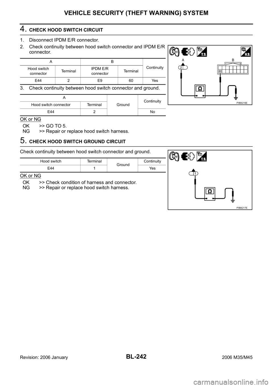
4. CHECK HOOD SWITCH CIRCUIT
1. Disconnect IPDM E/R connector.
2. Check continuity between hood switch connector and IPDM E/R
connector.
3. Check continuity between hood switch connector and ground.
OK or NG
OK >> GO TO 5.
NG >> Repair or replace hood switch harness.
5. CHECK HOOD SWITCH GROUND CIRCUIT
Check continuity between hood switch connector and ground.
OK or NG
OK >> Check condition of harness and connector.
NG >> Repair or replace hood switch harness.
AB
Continuity
Hood switch
connectorTe r m i n a lIPDM E/R
connectorTerminal
E44 2 E9 60 Yes
A
GroundContinuity
Hood switch connector Terminal
E44 2 No
PIIB6216E
Hood switch Terminal
GroundContinuity
E44 1 Yes
PIIB6217E
Page 1183 of 5621
BL-244
VEHICLE SECURITY (THEFT WARNING) SYSTEM
Revision: 2006 January2006 M35/M45
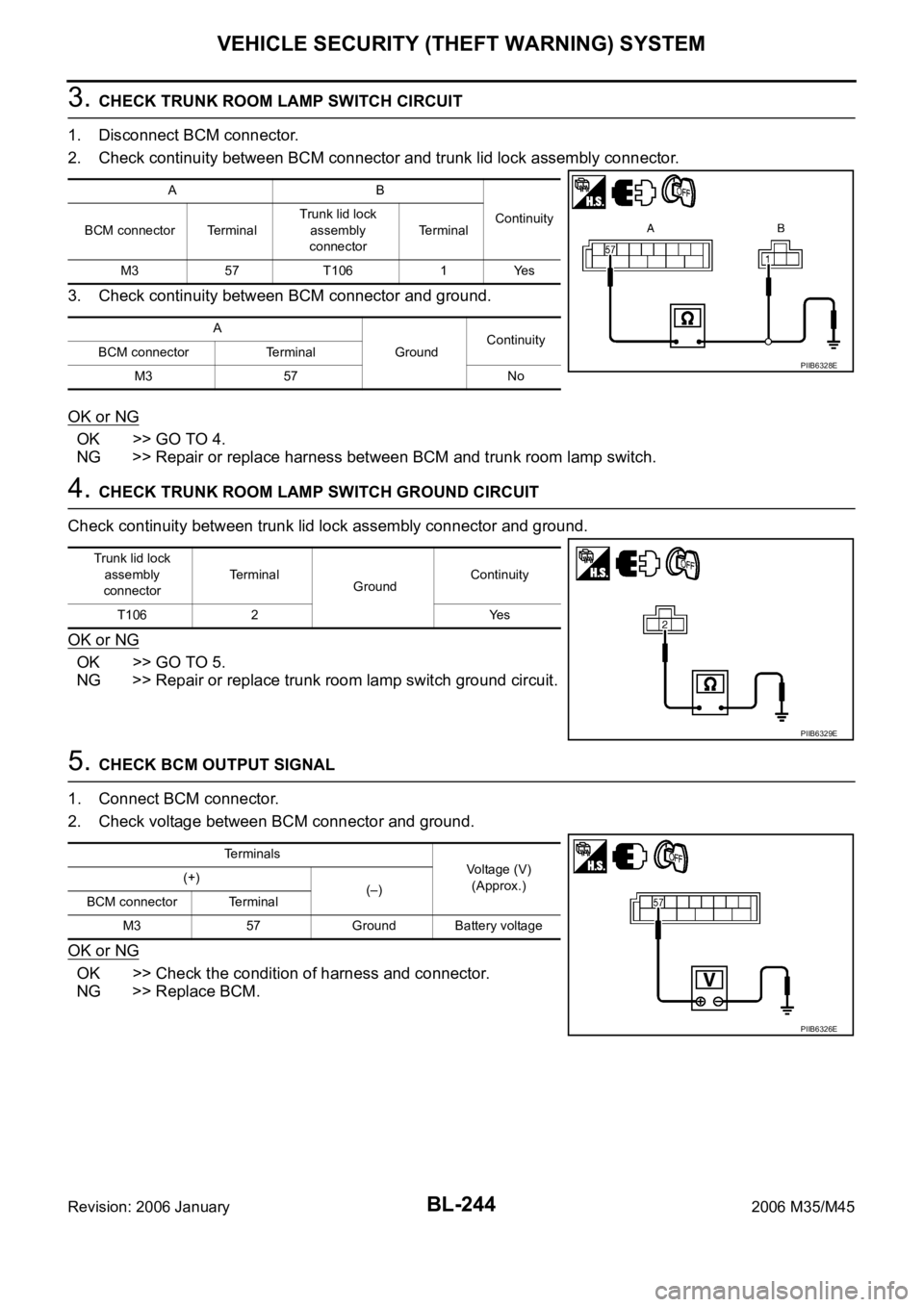
3. CHECK TRUNK ROOM LAMP SWITCH CIRCUIT
1. Disconnect BCM connector.
2. Check continuity between BCM connector and trunk lid lock assembly connector.
3. Check continuity between BCM connector and ground.
OK or NG
OK >> GO TO 4.
NG >> Repair or replace harness between BCM and trunk room lamp switch.
4. CHECK TRUNK ROOM LAMP SWITCH GROUND CIRCUIT
Check continuity between trunk lid lock assembly connector and ground.
OK or NG
OK >> GO TO 5.
NG >> Repair or replace trunk room lamp switch ground circuit.
5. CHECK BCM OUTPUT SIGNAL
1. Connect BCM connector.
2. Check voltage between BCM connector and ground.
OK or NG
OK >> Check the condition of harness and connector.
NG >> Replace BCM.
AB
Continuity
BCM connector TerminalTrunk lid lock
assembly
connectorTerminal
M3 57 T106 1 Yes
A
GroundContinuity
BCM connector Terminal
M3 57 No
PIIB6328E
Trunk lid lock
assembly
connectorTerminal
GroundContinuity
T106 2 Yes
PIIB6329E
Terminals
Voltage (V)
(Approx.) (+)
(–)
BCM connector Terminal
M3 57 Ground Battery voltage
PIIB6326E
Page 1218 of 5621
IVIS (INFINITI VEHICLE IMMOBILIZER SYSTEM-NATS)
BL-279
C
D
E
F
G
H
J
K
L
MA
B
BL
Revision: 2006 January2006 M35/M45
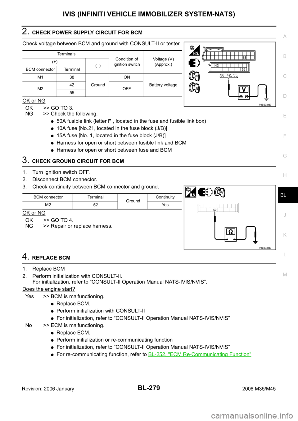
2. CHECK POWER SUPPLY CIRCUIT FOR BCM
Check voltage between BCM and ground with CONSULT-II or tester.
OK or NG
OK >> GO TO 3.
NG >> Check the following.
50A fusible link (letter F , located in the fuse and fusible link box)
10A fuse [No.21, located in the fuse block (J/B)]
15A fuse [No. 1, located in the fuse block (J/B)]
Harness for open or short between fusible link and BCM
Harness for open or short between fuse and BCM
3. CHECK GROUND CIRCUIT FOR BCM
1. Turn ignition switch OFF.
2. Disconnect BCM connector.
3. Check continuity between BCM connector and ground.
OK or NG
OK >> GO TO 4.
NG >> Repair or replace harness.
4. REPLACE BCM
1. Replace BCM
2. Perform initialization with CONSULT-II.
For initialization, refer to “CONSULT-II Operation Manual NATS-IVIS/NVIS”.
Does the engine start?
Yes >> BCM is malfunctioning.
Replace BCM.
Perform initialization with CONSULT-II
For initialization, refer to “CONSULT-II Operation Manual NATS-IVIS/NVIS”
No >> ECM is malfunctioning.
Replace ECM.
Perform initialization or re-communicating function
For initialization, refer to “CONSULT-II Operation Manual NATS-IVIS/NVIS”
For re-communicating function, refer to BL-252, "ECM Re-Communicating Function"
Terminals
Condition of
ignition switchVoltage (V)
(Approx.) (+)
(–)
BCM connector Terminal
M1 38
GroundON
Battery voltage
M242
OFF
55
PIIB5934E
BCM connector Terminal
GroundContinuity
M2 52 Yes
PIIB5935E
Page 1309 of 5621
BR-34
REAR DISC BRAKE
Revision: 2006 January2006 M35/M45
DISC ROTOR INSPECTION
Visual Inspection
Check surface of disc rotor for uneven wear, cracks, and serious damage. Replace if there are.
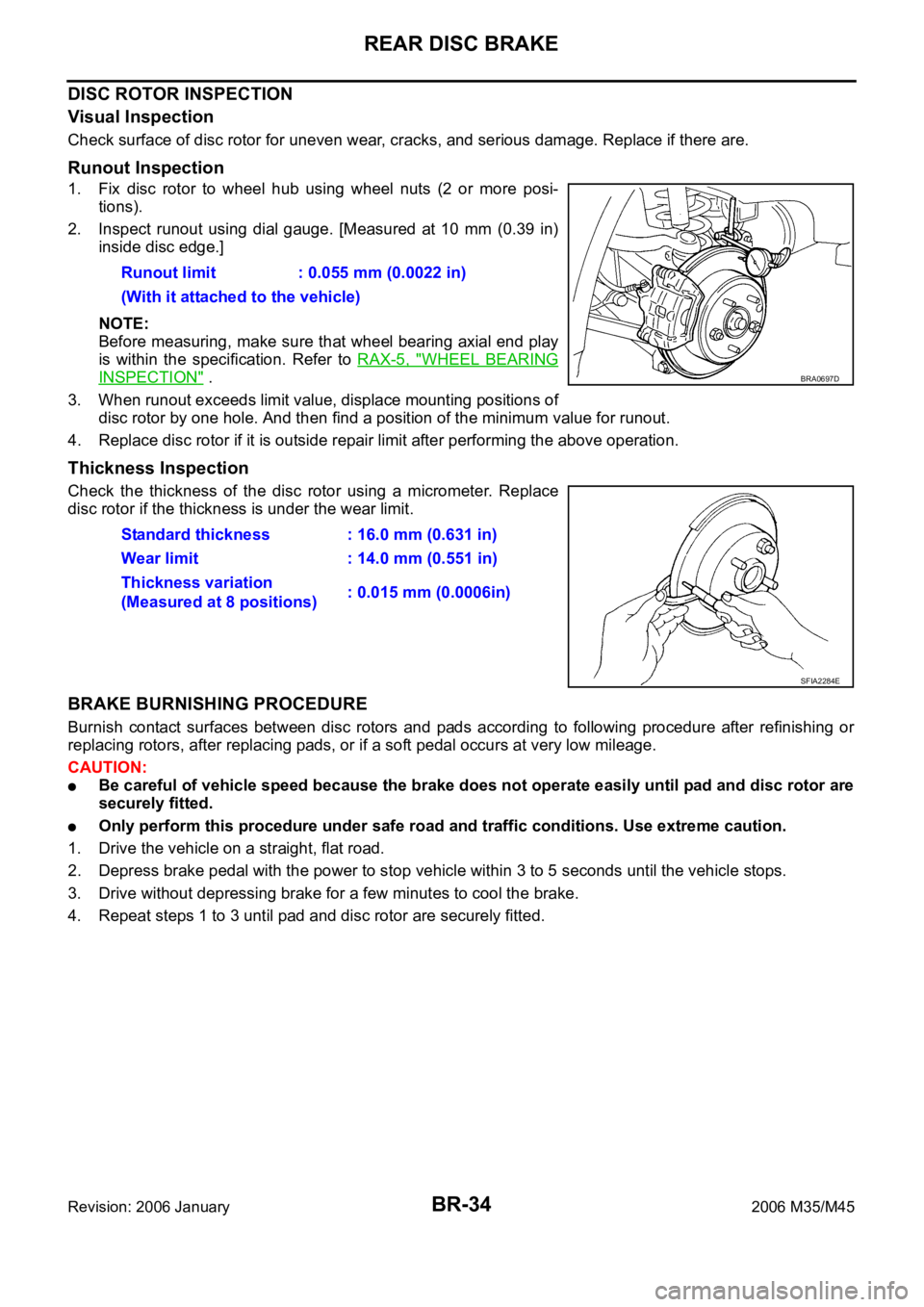
Runout Inspection
1. Fix disc rotor to wheel hub using wheel nuts (2 or more posi-
tions).
2. Inspect runout using dial gauge. [Measured at 10 mm (0.39 in)
inside disc edge.]
NOTE:
Before measuring, make sure that wheel bearing axial end play
is within the specification. Refer to RAX-5, "
WHEEL BEARING
INSPECTION" .
3. When runout exceeds limit value, displace mounting positions of
disc rotor by one hole. And then find a position of the minimum value for runout.
4. Replace disc rotor if it is outside repair limit after performing the above operation.
Thickness Inspection
Check the thickness of the disc rotor using a micrometer. Replace
disc rotor if the thickness is under the wear limit.
BRAKE BURNISHING PROCEDURE
Burnish contact surfaces between disc rotors and pads according to following procedure after refinishing or
replacing rotors, after replacing pads, or if a soft pedal occurs at very low mileage.
CAUTION:
Be careful of vehicle speed because the brake does not operate easily until pad and disc rotor are
securely fitted.
Only perform this procedure under safe road and traffic conditions. Use extreme caution.
1. Drive the vehicle on a straight, flat road.
2. Depress brake pedal with the power to stop vehicle within 3 to 5 seconds until the vehicle stops.
3. Drive without depressing brake for a few minutes to cool the brake.
4. Repeat steps 1 to 3 until pad and disc rotor are securely fitted. Runout limit : 0.055 mm (0.0022 in)
(With it attached to the vehicle)
BRA0697D
Standard thickness : 16.0 mm (0.631 in)
Wear limit : 14.0 mm (0.551 in)
Thickness variation
(Measured at 8 positions): 0.015 mm (0.0006in)
SFIA2284E
Page 1337 of 5621
![INFINITI M35 2006 Factory Service Manual BRC-26
[VDC/TCS/ABS]
TROUBLE DIAGNOSIS
Revision: 2006 January2006 M35/M45
Note 1: After completing repairs of shorted sensor circuit, when ignition switch is turned ON, ABS warning lamp turns on. Make INFINITI M35 2006 Factory Service Manual BRC-26
[VDC/TCS/ABS]
TROUBLE DIAGNOSIS
Revision: 2006 January2006 M35/M45
Note 1: After completing repairs of shorted sensor circuit, when ignition switch is turned ON, ABS warning lamp turns on. Make](/manual-img/42/57023/w960_57023-1336.png)
BRC-26
[VDC/TCS/ABS]
TROUBLE DIAGNOSIS
Revision: 2006 January2006 M35/M45
Note 1: After completing repairs of shorted sensor circuit, when ignition switch is turned ON, ABS warning lamp turns on. Make sure that
ABS warning lamp turns off while driving vehicle at 30 km/h (19 MPH) or more for approximately 1 minute according to self-diagnosis
procedure. In addition, if wheel sensor 2 is displayed for wheels, check wheel sensor circuit and also check control unit power voltage.
Note 2: When malfunctions are detected in several systems, including CAN communication circuit [U1000], troubleshoot CAN communi-
cation circuit. Refer to BRC-51, "
Inspection 16: CAN Communication Circuit" . C1147 USV LINE [FL-RR]VDC switch-over solenoid valve (USV1) on the primary side is
open circuit or shorted, or the control line is open or shorted to
the power supply or the ground.
BRC-40,
"Inspection 6:
Solenoid, VDC
Change-Over
Valve and Actua-
tor Relay Circuit"
C1148 USV LINE [FR-RL]VDC switch-over solenoid valve (USV2) on the secondary side is
open circuit or shorted, or the control line is open or shorted to
the power supply or the ground.
C1149 HSV LINE [FL-RR]VDC switch-over solenoid valve (HSV1) on the primary side is
open circuit or shorted, or the control line is open or shorted to
the power supply or the ground.
C1150 HSV LINE [FR-RL]VDC switch-over solenoid valve (HSV2) on the secondary side is
open circuit or shorted, or the control line is open or shorted to
the power supply or the ground.
C1153 EMERGENCY BRAKEWhen ABS actuator and electric unit (control unit) is malfunction-
ing. (pressure increase is too much or too little)BRC-36,
"Inspection 3:
ABS Actuator
and Electric Unit
(Control Unit)"
C1154 PNP POS SIGTCM or ABS actuator and electric unit (control unit) internal mal-
function.BRC-43,
"Inspection 9:
Park/Neutral
Position (PNP)
Switch Circuit"
C1155 BR FLUID LEVEL LOWBrake fluid level is low or communication line between the ABS
actuator and electric unit (control unit) and brake fluid level switch
is open or shorted. BRC-48,
"Inspection 12:
Brake Fluid
Level Switch Cir-
cuit"
C1156 ST ANG SEN COM CIRCAN communication circuit or steering angle sensor is malfunc-
tioning.BRC-51, "Inspection 16:
CAN Communi-
cation Circuit"
C1170 VARIANT CODING In a case where VARIANT CODING is different.BRC-36,
"Inspection 3:
ABS Actuator
and Electric Unit
(Control Unit)"
C1185 ACC CONT ICC sensor integrated unit internal malfunction.BRC-50,
"Inspection 14:
ICC Sensor Inte-
grated Unit Cir-
cuit (With ICC)"
U1000 CAN COMM CIRCUIT When there is a malfunction in the CAN communication circuit.BRC-51,
"Inspection 16:
CAN Communi-
cation Circuit"
(Note 2)
U1100 ACC COMM CIRCUITWhen there is a malfunction in the CAN communication circuit or
ICC sensor integrated unit.BRC-51,
"Inspection 16:
CAN Communi-
cation Circuit"
Code Display item Malfunction detecting condition Check item
Page 1341 of 5621
![INFINITI M35 2006 Factory Service Manual BRC-30
[VDC/TCS/ABS]
TROUBLE DIAGNOSIS
Revision: 2006 January2006 M35/M45
Note 1: Confirm tire pressure is normal.
Note 2: Only AWD model.
Note 3: A brief moment of ON/OFF condition occurs every 20 se INFINITI M35 2006 Factory Service Manual BRC-30
[VDC/TCS/ABS]
TROUBLE DIAGNOSIS
Revision: 2006 January2006 M35/M45
Note 1: Confirm tire pressure is normal.
Note 2: Only AWD model.
Note 3: A brief moment of ON/OFF condition occurs every 20 se](/manual-img/42/57023/w960_57023-1340.png)
BRC-30
[VDC/TCS/ABS]
TROUBLE DIAGNOSIS
Revision: 2006 January2006 M35/M45
Note 1: Confirm tire pressure is normal.
Note 2: Only AWD model.
Note 3: A brief moment of ON/OFF condition occurs every 20 seconds after ignition switch turned ON. This is not malfunction because it
is an operation for checking.
Note 4: On and off timing for warning lamp and indicator lanp.Refer to BRC-33, "
ON and OFF Timing for Warning Lamp and Indicator
Lamp" .
Active TestNFS000QI
CAUTION:
Do not perform active test while driving vehicle.
Make sure to completely bleed air from brake system.
The active test cannot be performed with the ABS warning lamp, VDC indicator lamp, SLIP indica-
tor lamp and brake warning lamp are on.
ABS warning lamp, VDC OFF indicator lamp, SLIP indicator lamp and brake warning lamp are on
during active test.
Erase memory of ICC system after implementing active test. Refer to ACS-34, "Self-Diagnostic
Function" .
OPERATION PROCEDURE
1. Touch “START (NISSAN BASED VHCL)”, “ABS”, “ACTIVE TEST” in order on the CONSULT-II screen.
CAUTION:
When “START (NISSAN BASED VHCL)” is touched immediately after starting engine or turning on
ignition switch, “ABS” might not be displayed in the "SELECT SYSTEM" screen. In this case,
repeat the operation from step 1.
2. Touch “SELECT TEST ITEM” is displayed.
3. Touch necessary test item.
4. While “MAIN SIGNALS” indication is inverted, touch “START”.
5. “ACTIVE TEST” screen will be displayed so perform the following test.
SV/R OUTPUT
(Note 3)Solenoid valve relay activatedWhen the solenoid valve
relay is active (When igni-
tion switch OFF)ON
When the solenoid valve
relay is not active (in the
fail-safe mode)OFF
S M/R OUTPUTActuator motor and motor relay acti-
vatedWhen the actuator motor
and motor relay are active
(
ACTIVE TEST” with
CONSULT-II)ON
When the actuator motor
and motor relay are inac-
tiveOFF E: ECU INPUT SIGNALS M: MAIN SIGNALS S: SELECTION FROM MENU
SELECT
MONITOR
ITEM Monitor item Display contentData monitor
ConditionReference value in
normal operation
SFIA0591E