Page 1033 of 5621
BL-94
INTELLIGENT KEY SYSTEM
Revision: 2006 January2006 M35/M45
Check Key SlotNIS001XN
1. CHECK KEY SLOT INPUT SIGNAL
Check voltage between Intelligent Key unit harness connector and ground.
OK or NG
OK >> Key slot is OK.
NG >> GO TO 2.
2. CHECK KEY SLOT POWER SUPPLY CIRCUIT
1. Turn ignition switch OFF.
2. Disconnect key slot connector.
3. Check voltage between slot connector and ground.
OK or NG
OK >> GO TO 3.
NG >> Repair or replace key slot power supply circuit.
3. CHECK KEY SLOT
Check key slot.
OK or NG
OK >> GO TO 4.
NG >> Replace key slot.
Terminals
ConditionVoltage (V)
(Approx.) (+)
(–)
Intelligent Key
unit connectorTerminal
M32 19 GroundIntelligent Key inserted Battery voltage
Intelligent Key removed 0
PIIB6319E
Terminals
Voltage (V)
(Approx.) (+)
(–)
Key slot connector Terminal
M14 1 Ground Battery voltage
PIIB6320E
Terminal
Condition Continuity
Key slot
13Intelligent Key inserted Yes
Intelligent Key removed No
PIIB6321E
Page 1034 of 5621
INTELLIGENT KEY SYSTEM
BL-95
C
D
E
F
G
H
J
K
L
MA
B
BL
Revision: 2006 January2006 M35/M45
4. CHECK KEY SLOT GROUND CIRCUIT
Check continuity between key slot connector and ground.
OK or NG
OK >> GO TO 5.
NG >> Repair or replace key slot ground circuit.
5. CHECK KEY SWITCH CIRCUIT
1. Disconnect Intelligent Key unit connector.
2. Check continuity between Intelligent Key unit connector 7 and key slot connector.
3. Check continuity between Intelligent Key unit connector and
ground.
OK or NG
OK >> Check the condition of harness and harness connector.
NG >> Repair or replace harness between Intelligent Key unit and key slot.
Key slot connector Terminal
GroundContinuity
M14 8 Yes
PIIB6322E
AB
Continuity
Intelligent Key
unit connectorTerminal Key slot connector Terminal
M32 19 M14 2 Yes
A
GroundContinuity
Intelligent Key unit connector Terminal
M32 19 No
PIIB6323E
Page 1039 of 5621
BL-100
INTELLIGENT KEY SYSTEM
Revision: 2006 January2006 M35/M45
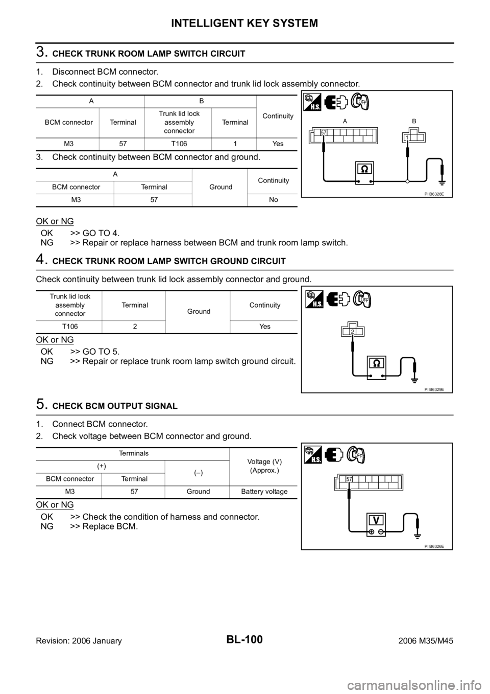
3. CHECK TRUNK ROOM LAMP SWITCH CIRCUIT
1. Disconnect BCM connector.
2. Check continuity between BCM connector and trunk lid lock assembly connector.
3. Check continuity between BCM connector and ground.
OK or NG
OK >> GO TO 4.
NG >> Repair or replace harness between BCM and trunk room lamp switch.
4. CHECK TRUNK ROOM LAMP SWITCH GROUND CIRCUIT
Check continuity between trunk lid lock assembly connector and ground.
OK or NG
OK >> GO TO 5.
NG >> Repair or replace trunk room lamp switch ground circuit.
5. CHECK BCM OUTPUT SIGNAL
1. Connect BCM connector.
2. Check voltage between BCM connector and ground.
OK or NG
OK >> Check the condition of harness and connector.
NG >> Replace BCM.
AB
Continuity
BCM connector TerminalTrunk lid lock
assembly
connectorTerminal
M3 57 T106 1 Yes
A
GroundContinuity
BCM connector Terminal
M3 57 No
PIIB6328E
Trunk lid lock
assembly
connectorTerminal
GroundContinuity
T106 2 Yes
PIIB6329E
Terminals
Voltage (V)
(Approx.) (+)
(–)
BCM connector Terminal
M3 57 Ground Battery voltage
PIIB6326E
Page 1041 of 5621
BL-102
INTELLIGENT KEY SYSTEM
Revision: 2006 January2006 M35/M45
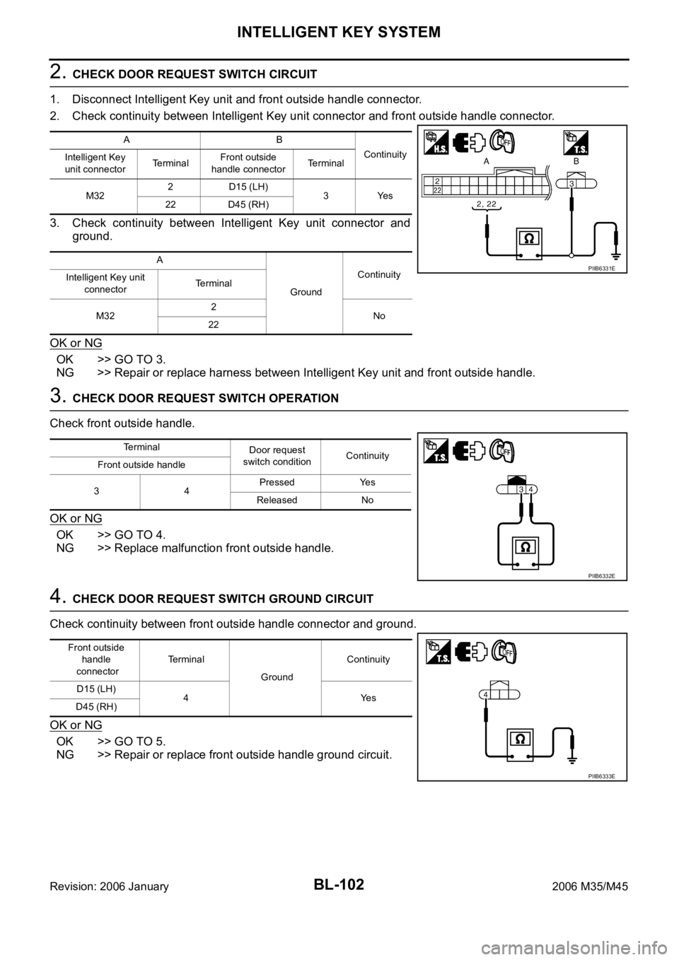
2. CHECK DOOR REQUEST SWITCH CIRCUIT
1. Disconnect Intelligent Key unit and front outside handle connector.
2. Check continuity between Intelligent Key unit connector and front outside handle connector.
3. Check continuity between Intelligent Key unit connector and
ground.
OK or NG
OK >> GO TO 3.
NG >> Repair or replace harness between Intelligent Key unit and front outside handle.
3. CHECK DOOR REQUEST SWITCH OPERATION
Check front outside handle.
OK or NG
OK >> GO TO 4.
NG >> Replace malfunction front outside handle.
4. CHECK DOOR REQUEST SWITCH GROUND CIRCUIT
Check continuity between front outside handle connector and ground.
OK or NG
OK >> GO TO 5.
NG >> Repair or replace front outside handle ground circuit.
AB
Continuity
Intelligent Key
unit connectorTe r m i n a lFront outside
handle connectorTerminal
M322 D15 (LH)
3Yes
22 D45 (RH)
A
GroundContinuity
Intelligent Key unit
connectorTerminal
M322
No
22
PIIB6331E
Terminal
Door request
switch conditionContinuity
Front outside handle
34Pressed Yes
Released No
PIIB6332E
Front outside
handle
connectorTe r m i n a l
GroundContinuity
D15 (LH)
4Yes
D45 (RH)
PIIB6333E
Page 1043 of 5621
BL-104
INTELLIGENT KEY SYSTEM
Revision: 2006 January2006 M35/M45
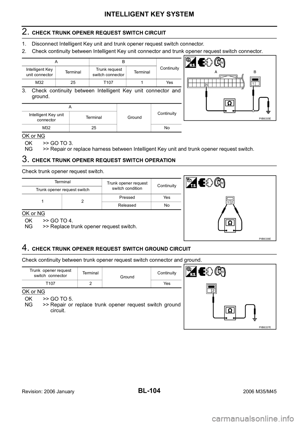
2. CHECK TRUNK OPENER REQUEST SWITCH CIRCUIT
1. Disconnect Intelligent Key unit and trunk opener request switch connector.
2. Check continuity between Intelligent Key unit connector and trunk opener request switch connector.
3. Check continuity between Intelligent Key unit connector and
ground.
OK or NG
OK >> GO TO 3.
NG >> Repair or replace harness between Intelligent Key unit and trunk opener request switch.
3. CHECK TRUNK OPENER REQUEST SWITCH OPERATION
Check trunk opener request switch.
OK or NG
OK >> GO TO 4.
NG >> Replace trunk opener request switch.
4. CHECK TRUNK OPENER REQUEST SWITCH GROUND CIRCUIT
Check continuity between trunk opener request switch connector and ground.
OK or NG
OK >> GO TO 5.
NG >> Repair or replace trunk opener request switch ground
circuit.
AB
Continuity
Intelligent Key
unit connectorTerminal Trunk request
switch connectorTerminal
M32 25 T107 1 Yes
A
GroundContinuity
Intelligent Key unit
connectorTe r m i n a l
M32 25 No
PIIB6335E
Terminal
Trunk opener request
switch conditionContinuity
Trunk opener request switch
12Pressed Yes
Released No
PIIB6336E
Trunk opener request
switch connectorTerminal
GroundContinuity
T107 2 Yes
PIIB6337E
Page 1046 of 5621

INTELLIGENT KEY SYSTEM
BL-107
C
D
E
F
G
H
J
K
L
MA
B
BL
Revision: 2006 January2006 M35/M45
Check Intelligent Key Warning BuzzerNIS001XT
1. CHECK INTELLIGENT KEY WARNING BUZZER
Check voltage between Intelligent Key unit connector and ground.
OK or NG
OK >> Intelligent Key warning buzzer is OK.
NG >> GO TO 2.
2. CHECK INTELLIGENT KEY WARNING BUZZER POWER SUPPLY CIRCUIT
1. Turn ignition switch OFF.
2. Disconnect Intelligent Key warning buzzer connector.
3. Check voltage between Intelligent Key warning buzzer connector and ground.
OK or NG
OK >> GO TO 3.
NG >> Repair or replace Intelligent Key warning buzzer power
supply circuit.
3. CHECK INTELLIGENT KEY WARNING BUZZER CIRCUIT
1. Disconnect Intelligent Key unit connector.
2. Check continuity between Intelligent Key unit connector and Intelligent Key warning buzzer connector.
3. Check continuity between Intelligent Key unit connector and
ground.
OK or NG
OK >> GO TO 4.
NG >> Repair or replace harness between Intelligent Key unit and Intelligent Key warning buzzer.
Te r m i n a l s
Warning
buzzer opera-
tion conditionVoltage (V)
(Approx.) (+)
(–)
Intelligent Key
unit connectorTerminal
M33 55 GroundYe s 0
No Battery voltage
PIIB6341E
Terminals
Voltage (V)
(Approx.) (+)
(–) Intelligent Key
warning buzzer
connectorTerminal
E37 3 Ground Battery voltage
PIIB6342E
AB
Continuity
Intelligent Key
unit connectorTerminalIntelligent Key
warning buzzer
connectorTerminal
M33 55 E37 1 Yes
A
GroundContinuity
Intelligent Key unit
connectorTerminal
M33 55 No
PIIB6343E
Page 1048 of 5621
INTELLIGENT KEY SYSTEM
BL-109
C
D
E
F
G
H
J
K
L
MA
B
BL
Revision: 2006 January2006 M35/M45
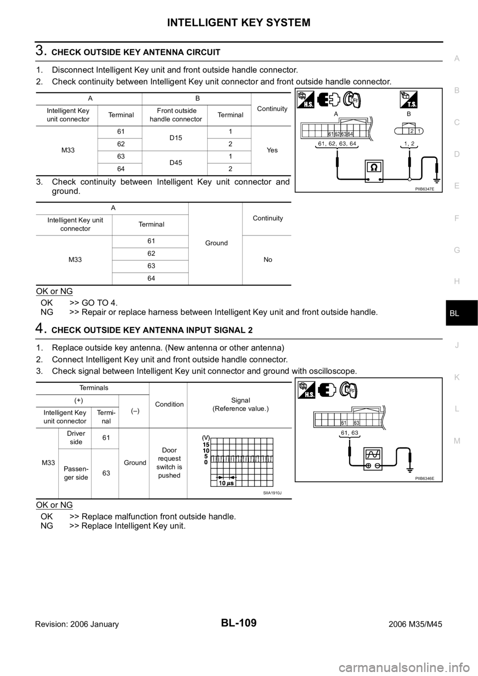
3. CHECK OUTSIDE KEY ANTENNA CIRCUIT
1. Disconnect Intelligent Key unit and front outside handle connector.
2. Check continuity between Intelligent Key unit connector and front outside handle connector.
3. Check continuity between Intelligent Key unit connector and
ground.
OK or NG
OK >> GO TO 4.
NG >> Repair or replace harness between Intelligent Key unit and front outside handle.
4. CHECK OUTSIDE KEY ANTENNA INPUT SIGNAL 2
1. Replace outside key antenna. (New antenna or other antenna)
2. Connect Intelligent Key unit and front outside handle connector.
3. Check signal between Intelligent Key unit connector and ground with oscilloscope.
OK or NG
OK >> Replace malfunction front outside handle.
NG >> Replace Intelligent Key unit.
AB
Continuity
Intelligent Key
unit connectorTerminal Front outside
handle connectorTerminal
M3361
D151
Ye s 62 2
63
D451
64 2
A
GroundContinuity
Intelligent Key unit
connectorTerminal
M3361
No 62
63
64
PIIB6347E
Terminals
ConditionSignal
(Reference value.) (+)
(–)
Intelligent Key
unit connectorTe r m i -
nal
M33Driver
side61
GroundDoor
request
switch is
pushed Passen-
ger side63
PIIB6346E
SIIA1910J
Page 1050 of 5621
INTELLIGENT KEY SYSTEM
BL-111
C
D
E
F
G
H
J
K
L
MA
B
BL
Revision: 2006 January2006 M35/M45
3. CHECK OUTSIDE KEY ANTENNA CIRCUIT
1. Disconnect Intelligent Key unit and outside key antenna (trunk room) connector.
2. Check continuity between Intelligent Key unit connector and outside key antenna (trunk room) connector.
3. Check continuity between Intelligent Key unit connector and
ground.
OK or NG
OK >> GO TO 4.
NG >> Repair or replace harness between Intelligent Key unit and outside key antenna (trunk room).
4. CHECK OUTSIDE KEY ANTENNA INPUT SIGNAL 2
1. Replace outside key antenna. (New antenna or other antenna)
2. Connect Intelligent Key unit and outside key antenna (trunk room) connector.
3. Check signal between Intelligent Key unit connector and ground with oscilloscope.
OK or NG
OK >> Replace malfunction front outside handle.
NG >> Replace Intelligent Key unit.
AB
Continuity
Intelligent Key
unit connectorTerminalOutside key
antenna (trunk
room) connectorTerminal
M3369
B1211
Ye s
70 2
A
GroundContinuity
Intelligent Key unit
connectorTerminal
M3369
No
70
PIIB6349E
Te r m i n a l s
ConditionSignal
(Reference value.) (+)
(–) Intelligent
Key unit
connectorTerminal
M33 69 GroundTrunk
request
switch is
pushed
PIIB6348E
SIIA1910J