Page 3673 of 4462
LIGHTING AND TURN SIGNAL SWITCH LT-111
C
D E
F
G H
I
J
L
M A
B
LT
Revision: 2006 December 2006 FX35/FX45
LIGHTING AND TURN SIGNAL SWITCHPFP:25540
Removal and InstallationNKS002XV
REMOVAL
1. Remove steering column cover. Refer to IP-10, "INSTRUMENT
PANEL ASSEMBLY" .
2. While pressing pawls in direction as shown in the figure, pull lighting and turn signal switch toward driver door and disconnect
from the base.
INSTALLATION
Installation is the reverse order of removal.
PKIB3477E
Page 3674 of 4462
LT-112
HAZARD SWITCH
Revision: 2006 December 2006 FX35/FX45
HAZARD SWITCHPFP:25290
Removal and InstallationNKS002XW
REMOVAL
1. Remove A/T console finisher. Refer to IP-10, "INSTRUMENT
PANEL ASSEMBLY" .
2. Disconnect the hazard switch connector.
3. Remove the drink holder.
4. Press pawl on reverse side and remove hazard switch.
INSTALLATION
Installation is the reverse order of removal.
PKIC9691E
Page 3684 of 4462
LT-122
COMBINATION SWITCH
Revision: 2006 December 2006 FX35/FX45
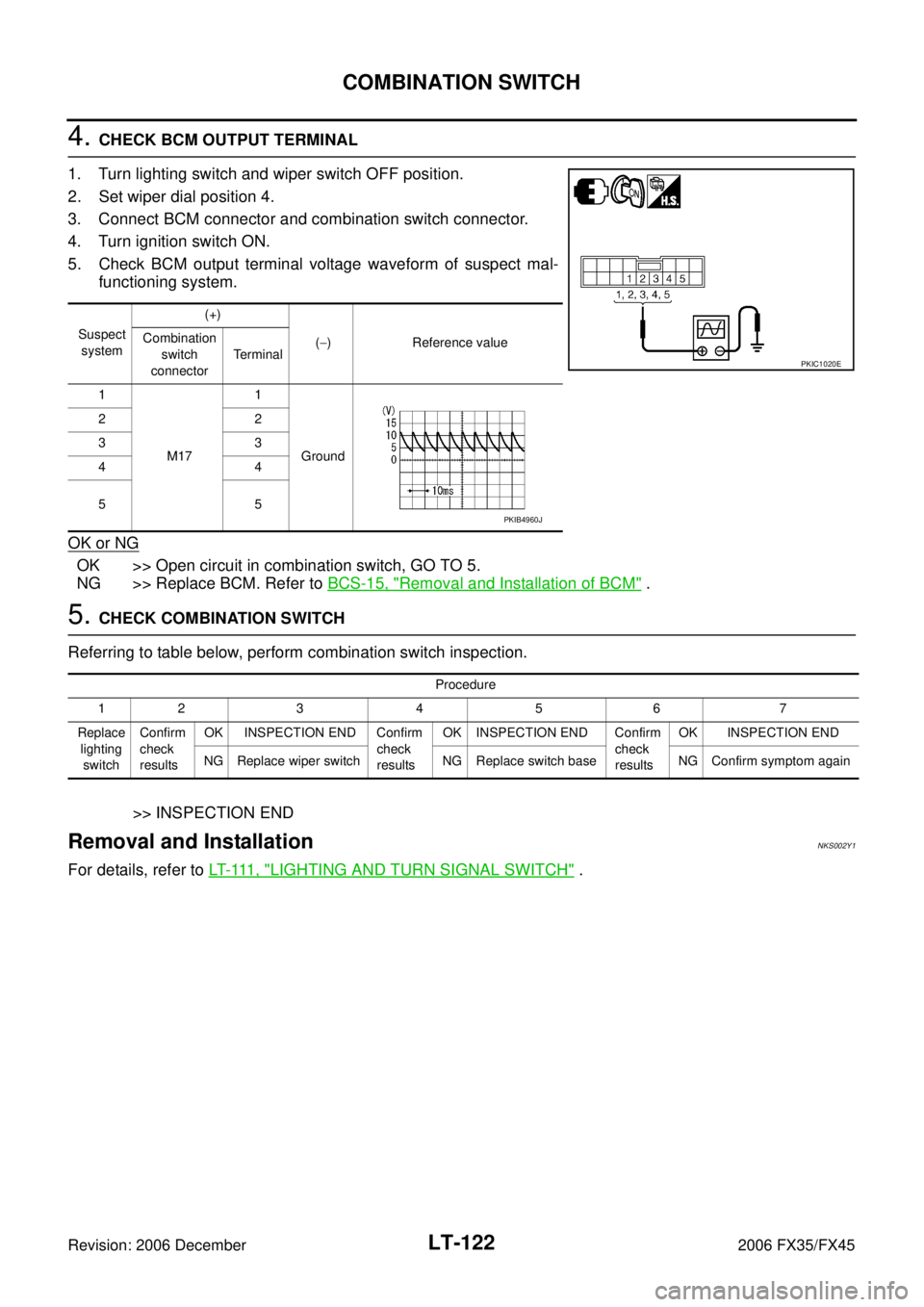
4. CHECK BCM OUTPUT TERMINAL
1. Turn lighting switch and wiper switch OFF position.
2. Set wiper dial position 4.
3. Connect BCM connector and combination switch connector.
4. Turn ignition switch ON.
5. Check BCM output terminal voltage waveform of suspect mal- functioning system.
OK or NG
OK >> Open circuit in combination switch, GO TO 5.
NG >> Replace BCM. Refer to BCS-15, "
Removal and Installation of BCM" .
5. CHECK COMBINATION SWITCH
Referring to table below, perform combination switch inspection.
>> INSPECTION END
Removal and InstallationNKS002Y1
For details, refer to LT- 111 , "LIGHTING AND TURN SIGNAL SWITCH" .
Suspect
system (+)
( − ) Reference value
Combination
switch
connector Terminal
1
M17 1
Ground
22
33
44
55
PKIC1020E
PKIB4960J
Procedure
12 3 4 5 6 7
Replace lighting switch Confirm
check
results OK INSPECTION END Confirm
check
results OK INSPECTION END Confirm
check
results OK INSPECTION END
NG Replace wiper switch NG Replace switch base NG Confirm symptom again
Page 3692 of 4462
LT-130
STOP LAMP
Revision: 2006 December 2006 FX35/FX45
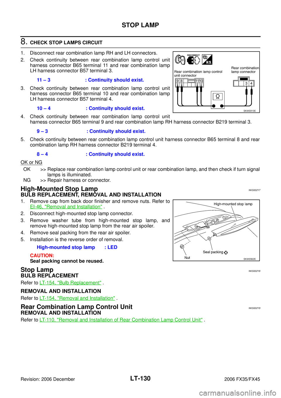
8. CHECK STOP LAMPS CIRCUIT
1. Disconnect rear combination lamp RH and LH connectors.
2. Check continuity between rear combination lamp control unit harness connector B65 terminal 11 and rear combination lamp
LH harness connector B57 terminal 3.
3. Check continuity between rear combination lamp control unit harness connector B65 terminal 10 and rear combination lamp
LH harness connector B57 terminal 4.
4. Check continuity between rear combination lamp control unit harness connector B65 terminal 9 and rear combination lamp RH harness connector B219 terminal 3.
5. Check continuity between rear combination lamp control unit harness connector B65 terminal 8 and rear combination lamp RH harness connector B219 terminal 4.
OK or NG
OK >> Replace rear combination lamp control unit or rear combination lamp, and then check if turn signal lamps is illuminated.
NG >> Repair harness or connector.
High-Mounted Stop LampNKS002Y7
BULB REPLACEMENT, REMOVAL AND INSTALLATION
1. Remove cap from back door finisher and remove nuts. Refer to EI-46, "
Removal and Installation" .
2. Disconnect high-mounted stop lamp connector.
3. Remove washer tube from high-mounted stop lamp, and remove high-mounted stop lamp from the rear air spoiler.
4. Remove seal packing from the rear air spoiler.
5. Installation is the reverse order of removal.
CAUTION:
Seal packing cannot be reused.
Stop LampNKS002Y8
BULB REPLACEMENT
Refer to LT- 1 5 4 , "Bulb Replacement" .
REMOVAL AND INSTALLATION
Refer to LT- 1 5 4 , "Removal and Installation" .
Rear Combination Lamp Control UnitNKS002Y9
REMOVAL AND INSTALLATION
Refer to LT- 11 0 , "Removal and Installation of Rear Combination Lamp Control Unit" .
11 – 3 : Continuity should exist.
10 – 4 : Continuity should exist.
9 – 3 : Continuity should exist.
8 – 4 : Continuity should exist.
SKIA5910E
High-mounted stop lamp : LED
SKIA5562E
Page 3694 of 4462
LT-132
BACK-UP LAMP
Revision: 2006 December 2006 FX35/FX45
Bulb ReplacementNKS003GX
Refer to LT- 1 5 4 , "Bulb Replacement" .
Removal and InstallationNKS003GY
Refer to LT- 1 5 4 , "Removal and Installation" .
Page 3708 of 4462
LT-146
PARKING, LICENSE PLATE AND TAIL LAMPS
Revision: 2006 December 2006 FX35/FX45
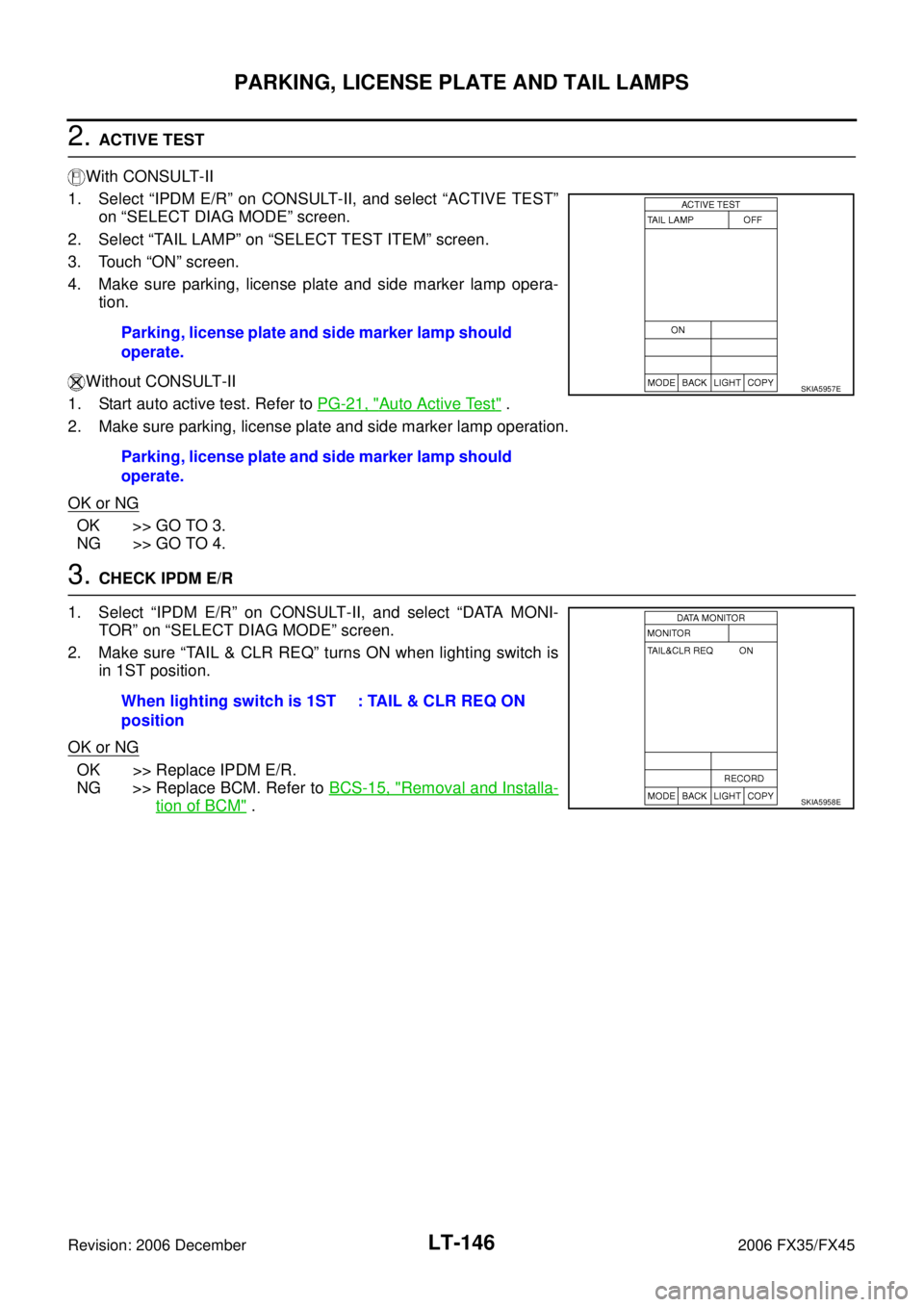
2. ACTIVE TEST
With CONSULT-II
1. Select “IPDM E/R” on CONSULT-II, and select “ACTIVE TEST” on “SELECT DIAG MODE” screen.
2. Select “TAIL LAMP” on “SELECT TEST ITEM” screen.
3. Touch “ON” screen.
4. Make sure parking, license plate and side marker lamp opera- tion.
Without CONSULT-II
1. Start auto active test. Refer to PG-21, "
Auto Active Test" .
2. Make sure parking, license plate and side marker lamp operation.
OK or NG
OK >> GO TO 3.
NG >> GO TO 4.
3. CHECK IPDM E/R
1. Select “IPDM E/R” on CONSULT-II, and select “DATA MONI- TOR” on “SELECT DIAG MODE” screen.
2. Make sure “TAIL & CLR REQ” turns ON when lighting switch is in 1ST position.
OK or NG
OK >> Replace IPDM E/R.
NG >> Replace BCM. Refer to BCS-15, "
Removal and Installa-
tion of BCM" .
Parking, license plate and side marker lamp should
operate.
Parking, license plate and side marker lamp should
operate.
SKIA5957E
When lighting switch is 1ST
position : TAIL & CLR REQ ON
SKIA5958E
Page 3714 of 4462
LT-152
PARKING, LICENSE PLATE AND TAIL LAMPS
Revision: 2006 December 2006 FX35/FX45
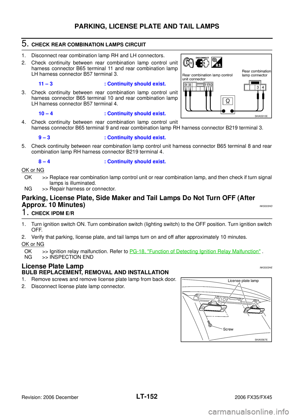
5. CHECK REAR COMBINATION LAMPS CIRCUIT
1. Disconnect rear combination lamp RH and LH connectors.
2. Check continuity between rear combination lamp control unit harness connector B65 terminal 11 and rear combination lamp
LH harness connector B57 terminal 3.
3. Check continuity between rear combination lamp control unit harness connector B65 terminal 10 and rear combination lamp
LH harness connector B57 terminal 4.
4. Check continuity between rear combination lamp control unit harness connector B65 terminal 9 and rear combination lamp RH harness connector B219 terminal 3.
5. Check continuity between rear combination lamp control unit harness connector B65 terminal 8 and rear combination lamp RH harness connector B219 terminal 4.
OK or NG
OK >> Replace rear combination lamp control unit or rear combination lamp, and then check if turn signal lamps is illuminated.
NG >> Repair harness or connector.
Parking, License Plate, Side Maker and Tail Lamps Do Not Turn OFF (After
Approx. 10 Minutes)
NKS003HD
1. CHECK IPDM E/R
1. Turn ignition switch ON. Turn combination switch (lighting switch) to the OFF position. Turn ignition switch OFF.
2. Verify that parking, license plate, and tail lamps turn on and off after approximately 10 minutes.
OK or NG
OK >> Ignition relay malfunction. Refer to PG-18, "Function of Detecting Ignition Relay Malfunction" .
NG >> INSPECTION END
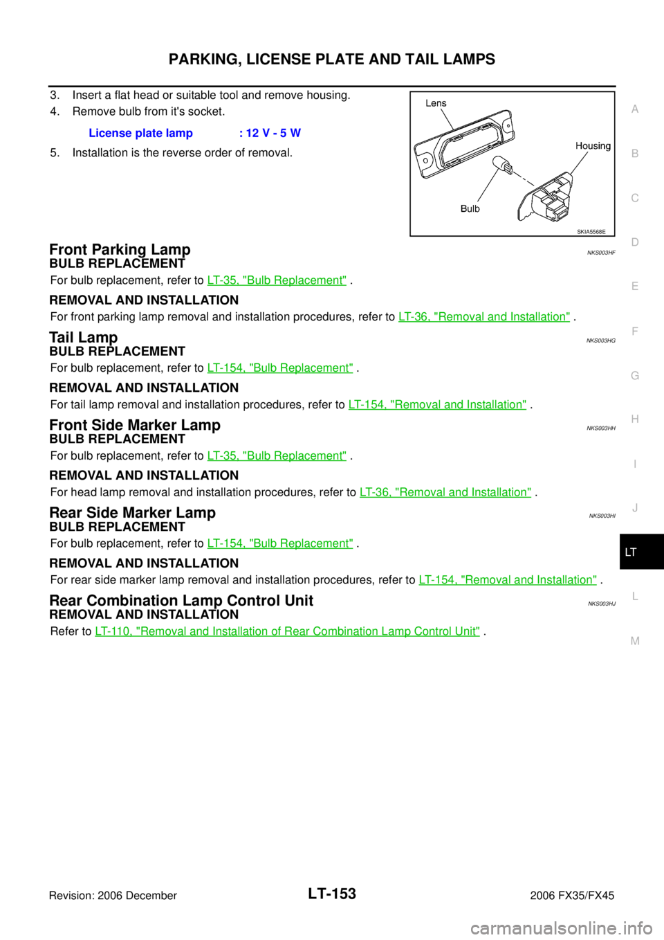
License Plate LampNKS003HE
BULB REPLACEMENT, REMOVAL AND INSTALLATION
1. Remove screws and remove license plate lamp from back door.
2. Disconnect license plate lamp connector. 11 – 3 : Continuity should exist.
10 – 4 : Continuity should exist.
9 – 3 : Continuity should exist.
8 – 4 : Continuity should exist.
SKIA5910E
SKIA5567E
Page 3715 of 4462
PARKING, LICENSE PLATE AND TAIL LAMPS LT-153
C
D E
F
G H
I
J
L
M A
B
LT
Revision: 2006 December 2006 FX35/FX45
3. Insert a flat head or suitable tool and remove housing.
4. Remove bulb from it's socket.
5. Installation is the reverse order of removal.
Front Parking LampNKS003HF
BULB REPLACEMENT
For bulb replacement, refer to LT- 3 5 , "Bulb Replacement" .
REMOVAL AND INSTALLATION
For front parking lamp removal and installation procedures, refer to LT- 3 6 , "Removal and Installation" .
Ta i l L a m pNKS003HG
BULB REPLACEMENT
For bulb replacement, refer to LT- 1 5 4 , "Bulb Replacement" .
REMOVAL AND INSTALLATION
For tail lamp removal and installation procedures, refer to LT- 1 5 4 , "Removal and Installation" .
Front Side Marker LampNKS003HH
BULB REPLACEMENT
For bulb replacement, refer to LT- 3 5 , "Bulb Replacement" .
REMOVAL AND INSTALLATION
For head lamp removal and installation procedures, refer to LT- 3 6 , "Removal and Installation" .
Rear Side Marker LampNKS003HI
BULB REPLACEMENT
For bulb replacement, refer to LT- 1 5 4 , "Bulb Replacement" .
REMOVAL AND INSTALLATION
For rear side marker lamp removal and installation procedures, refer to LT- 1 5 4 , "Removal and Installation" .
Rear Combination Lamp Control UnitNKS003HJ
REMOVAL AND INSTALLATION
Refer to LT- 11 0 , "Removal and Installation of Rear Combination Lamp Control Unit" .
License plate lamp : 12 V - 5 W
SKIA5568E