2006 INFINITI FX35 removal
[x] Cancel search: removalPage 3746 of 4462
LT-184
INTERIOR ROOM LAMP
Revision: 2006 December 2006 FX35/FX45
All Step Lamps Do Not OperateNKS002YY
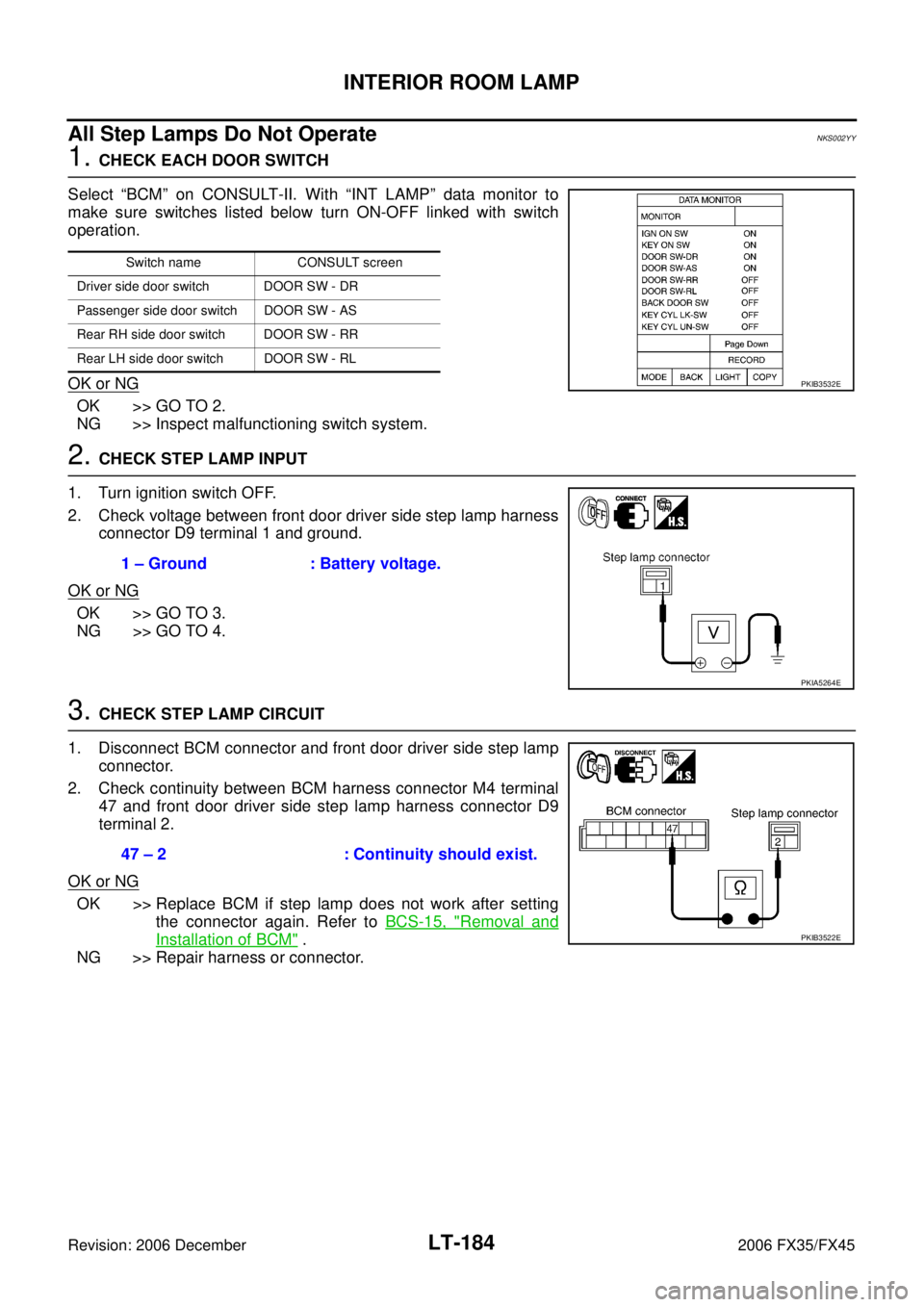
1. CHECK EACH DOOR SWITCH
Select “BCM” on CONSULT-II. With “INT LAMP” data monitor to
make sure switches listed below turn ON-OFF linked with switch
operation.
OK or NG
OK >> GO TO 2.
NG >> Inspect malfunctioning switch system.
2. CHECK STEP LAMP INPUT
1. Turn ignition switch OFF.
2. Check voltage between front door driver side step lamp harness connector D9 terminal 1 and ground.
OK or NG
OK >> GO TO 3.
NG >> GO TO 4.
3. CHECK STEP LAMP CIRCUIT
1. Disconnect BCM connector and front door driver side step lamp connector.
2. Check continuity between BCM harness connector M4 terminal 47 and front door driver side step lamp harness connector D9
terminal 2.
OK or NG
OK >> Replace BCM if step lamp does not work after setting the connector again. Refer to BCS-15, "
Removal and
Installation of BCM" .
NG >> Repair harness or connector.
Switch name CONSULT screen
Driver side door switch DOOR SW - DR
Passenger side door switch DOOR SW - AS
Rear RH side door switch DOOR SW - RR
Rear LH side door switch DOOR SW - RL
PKIB3532E
1 – Ground : Battery voltage.
PKIA5264E
47 – 2 : Continuity should exist.
PKIB3522E
Page 3747 of 4462
INTERIOR ROOM LAMP LT-185
C
D E
F
G H
I
J
L
M A
B
LT
Revision: 2006 December 2006 FX35/FX45
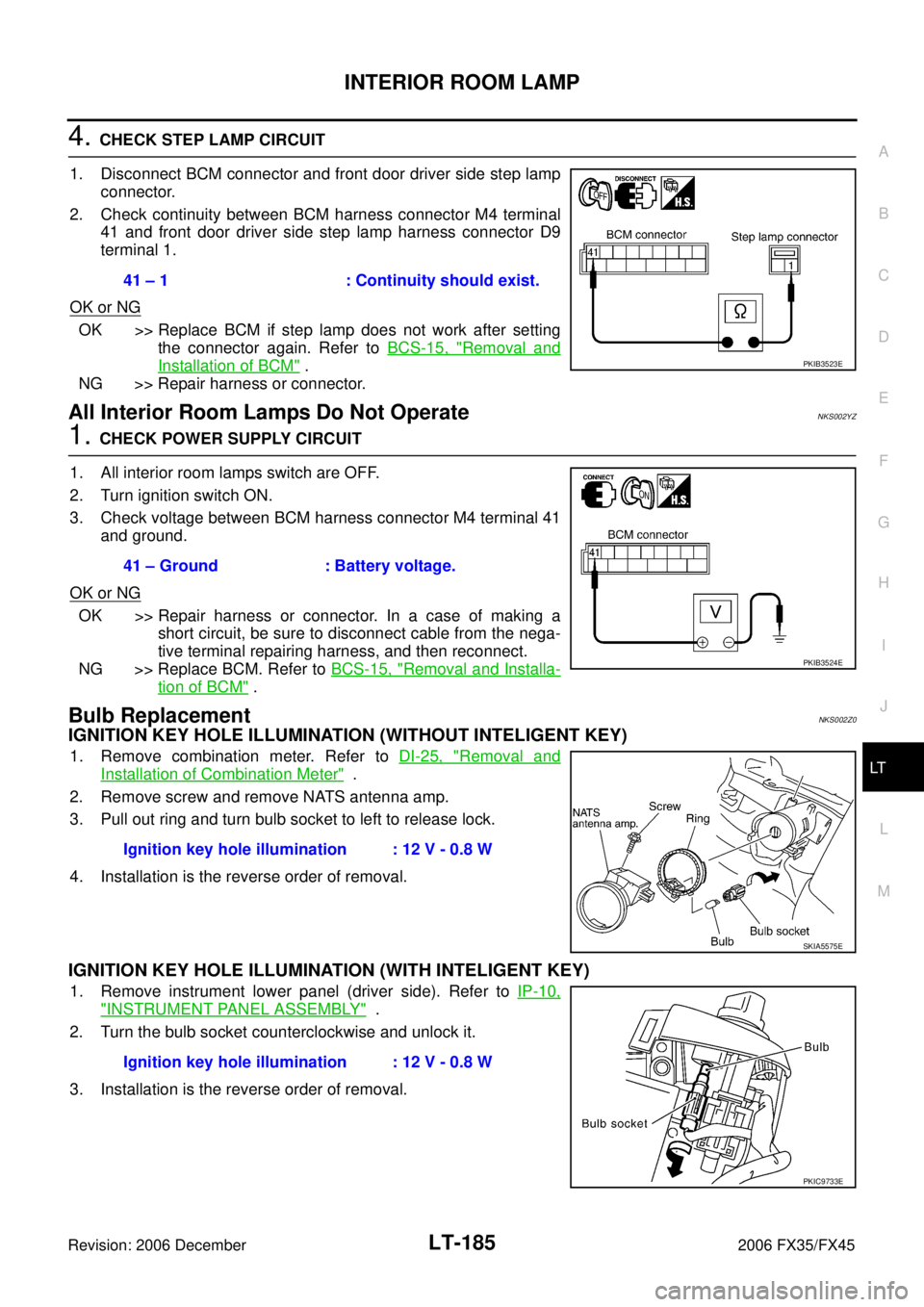
4. CHECK STEP LAMP CIRCUIT
1. Disconnect BCM connector and front door driver side step lamp connector.
2. Check continuity between BCM harness connector M4 terminal 41 and front door driver side step lamp harness connector D9
terminal 1.
OK or NG
OK >> Replace BCM if step lamp does not work after setting the connector again. Refer to BCS-15, "
Removal and
Installation of BCM" .
NG >> Repair harness or connector.
All Interior Room Lamps Do Not OperateNKS002YZ
1. CHECK POWER SUPPLY CIRCUIT
1. All interior room lamps switch are OFF.
2. Turn ignition switch ON.
3. Check voltage between BCM harness connector M4 terminal 41 and ground.
OK or NG
OK >> Repair harness or connector. In a case of making a short circuit, be sure to disconnect cable from the nega-
tive terminal repairing harness, and then reconnect.
NG >> Replace BCM. Refer to BCS-15, "
Removal and Installa-
tion of BCM" .
Bulb ReplacementNKS002Z0
IGNITION KEY HOLE ILLUMINATION (WITHOUT INTELIGENT KEY)
1. Remove combination meter. Refer to DI-25, "Removal and
Installation of Combination Meter" .
2. Remove screw and remove NATS antenna amp.
3. Pull out ring and turn bulb socket to left to release lock.
4. Installation is the reverse order of removal.
IGNITION KEY HOLE ILLUMINATION (WITH INTELIGENT KEY)
1. Remove instrument lower panel (driver side). Refer to IP-10,
"INSTRUMENT PANEL ASSEMBLY" .
2. Turn the bulb socket counterclockwise and unlock it.
3. Installation is the reverse order of removal. 41 – 1 : Continuity should exist.
PKIB3523E
41 – Ground : Battery voltage.
PKIB3524E
Ignition key hole illumination : 12 V - 0.8 W
SKIA5575E
Ignition key hole illumination : 12 V - 0.8 W
PKIC9733E
Page 3748 of 4462
LT-186
INTERIOR ROOM LAMP
Revision: 2006 December 2006 FX35/FX45
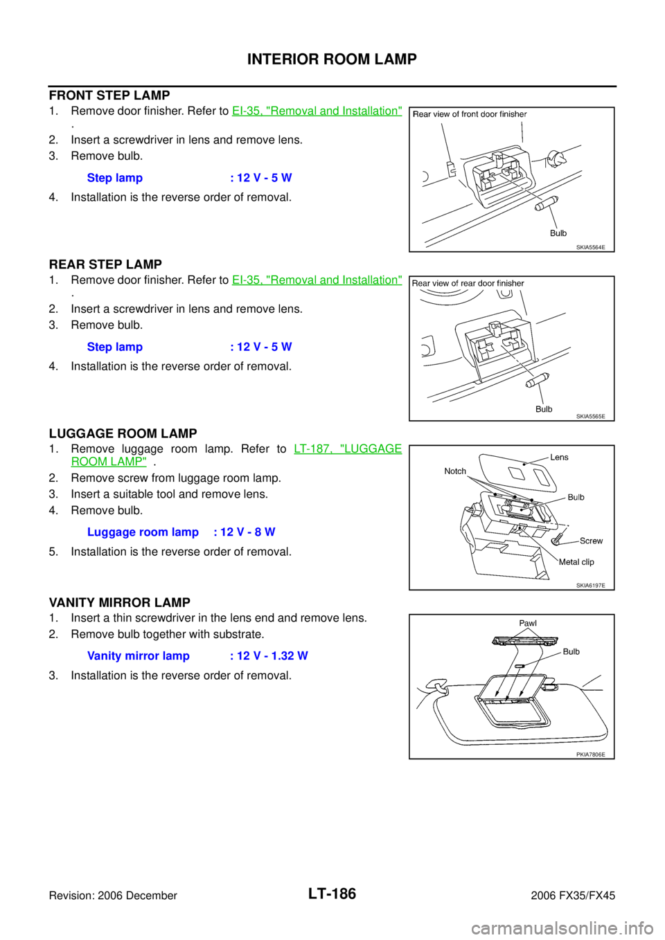
FRONT STEP LAMP
1. Remove door finisher. Refer to EI-35, "Removal and Installation"
.
2. Insert a screwdriver in lens and remove lens.
3. Remove bulb.
4. Installation is the reverse order of removal.
REAR STEP LAMP
1. Remove door finisher. Refer to EI-35, "Removal and Installation"
.
2. Insert a screwdriver in lens and remove lens.
3. Remove bulb.
4. Installation is the reverse order of removal.
LUGGAGE ROOM LAMP
1. Remove luggage room lamp. Refer to LT- 1 8 7 , "LUGGAGE
ROOM LAMP" .
2. Remove screw from luggage room lamp.
3. Insert a suitable tool and remove lens.
4. Remove bulb.
5. Installation is the reverse order of removal.
VANITY MIRROR LAMP
1. Insert a thin screwdriver in the lens end and remove lens.
2. Remove bulb together with substrate.
3. Installation is the reverse order of removal. Step lamp : 12 V - 5 W
SKIA5564E
Step lamp : 12 V - 5 W
SKIA5565E
Luggage room lamp : 12 V - 8 W
SKIA6197E
Vanity mirror lamp : 12 V - 1.32 W
PKIA7806E
Page 3749 of 4462
INTERIOR ROOM LAMP LT-187
C
D E
F
G H
I
J
L
M A
B
LT
Revision: 2006 December 2006 FX35/FX45
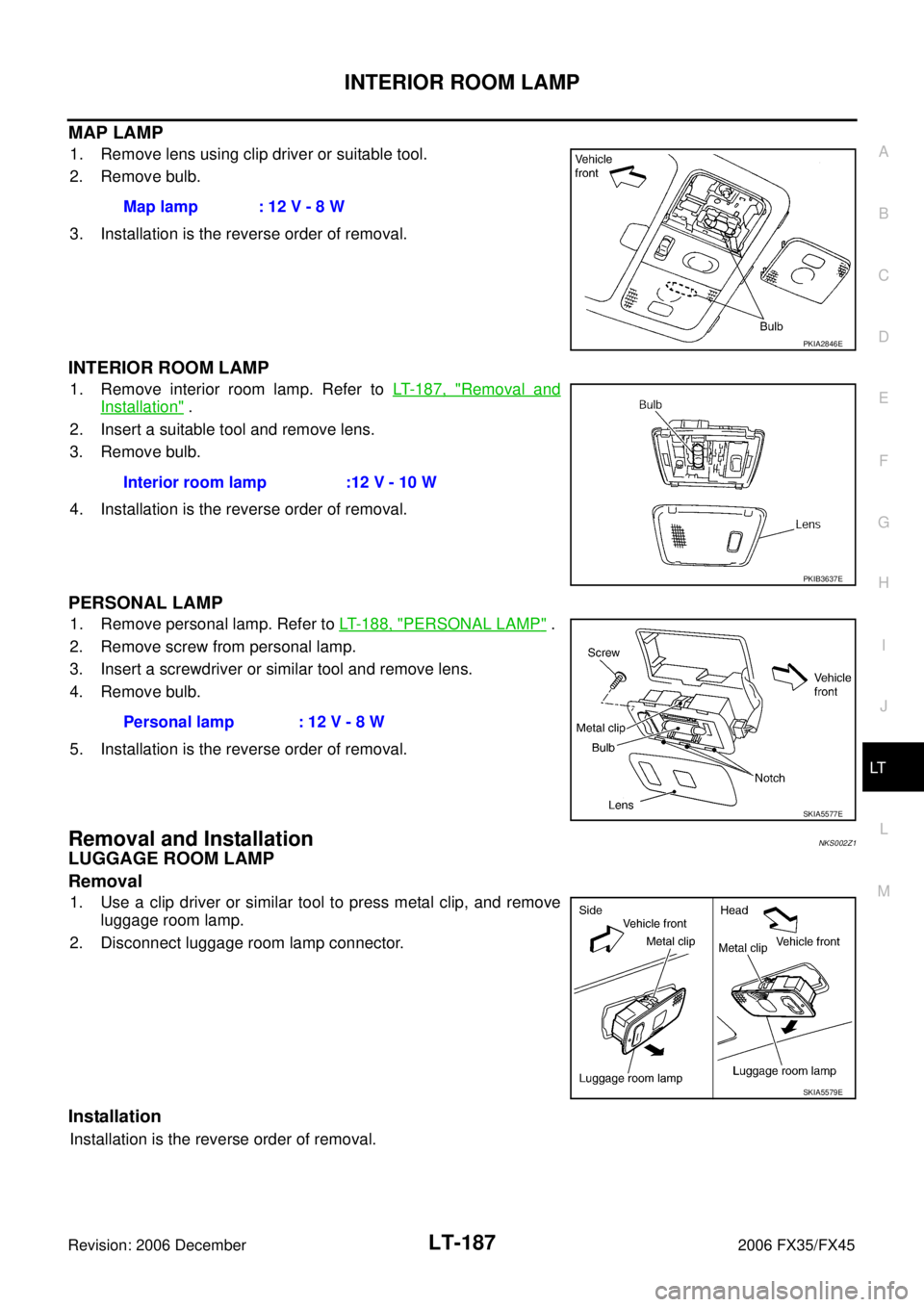
MAP LAMP
1. Remove lens using clip driver or suitable tool.
2. Remove bulb.
3. Installation is the reverse order of removal.
INTERIOR ROOM LAMP
1. Remove interior room lamp. Refer to LT- 1 8 7 , "Removal and
Installation" .
2. Insert a suitable tool and remove lens.
3. Remove bulb.
4. Installation is the reverse order of removal.
PERSONAL LAMP
1. Remove personal lamp. Refer to LT- 1 8 8 , "PERSONAL LAMP" .
2. Remove screw from personal lamp.
3. Insert a screwdriver or similar tool and remove lens.
4. Remove bulb.
5. Installation is the reverse order of removal.
Removal and InstallationNKS002Z1
LUGGAGE ROOM LAMP
Removal
1. Use a clip driver or similar tool to press metal clip, and remove luggage room lamp.
2. Disconnect luggage room lamp connector.
Installation
Installation is the reverse order of removal. Map lamp : 12 V - 8 W
PKIA2846E
Interior room lamp :12 V - 10 W
PKIB3637E
Personal lamp : 12 V - 8 W
SKIA5577E
SKIA5579E
Page 3750 of 4462
LT-188
INTERIOR ROOM LAMP
Revision: 2006 December 2006 FX35/FX45
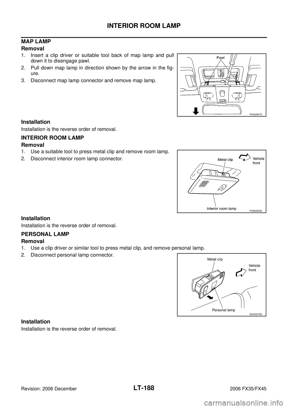
MAP LAMP
Removal
1. Insert a clip driver or suitable tool back of map lamp and pull down it to disengage pawl.
2. Pull down map lamp in direction shown by the arrow in the fig- ure.
3. Disconnect map lamp connector and remove map lamp.
Installation
Installation is the reverse order of removal.
INTERIOR ROOM LAMP
Removal
1. Use a suitable tool to press metal clip and remove room lamp.
2. Disconnect interior room lamp connector.
Installation
Installation is the reverse order of removal.
PERSONAL LAMP
Removal
1. Use a clip driver or similar tool to press metal clip, and remove personal lamp.
2. Disconnect personal lamp connector.
Installation
Installation is the reverse order of removal.
PKIA2847E
PKIB3525E
SKIA5578E
Page 3765 of 4462
ILLUMINATION LT-203
C
D E
F
G H
I
J
L
M A
B
LT
Revision: 2006 December 2006 FX35/FX45
Bulb ReplacementNKS003N7
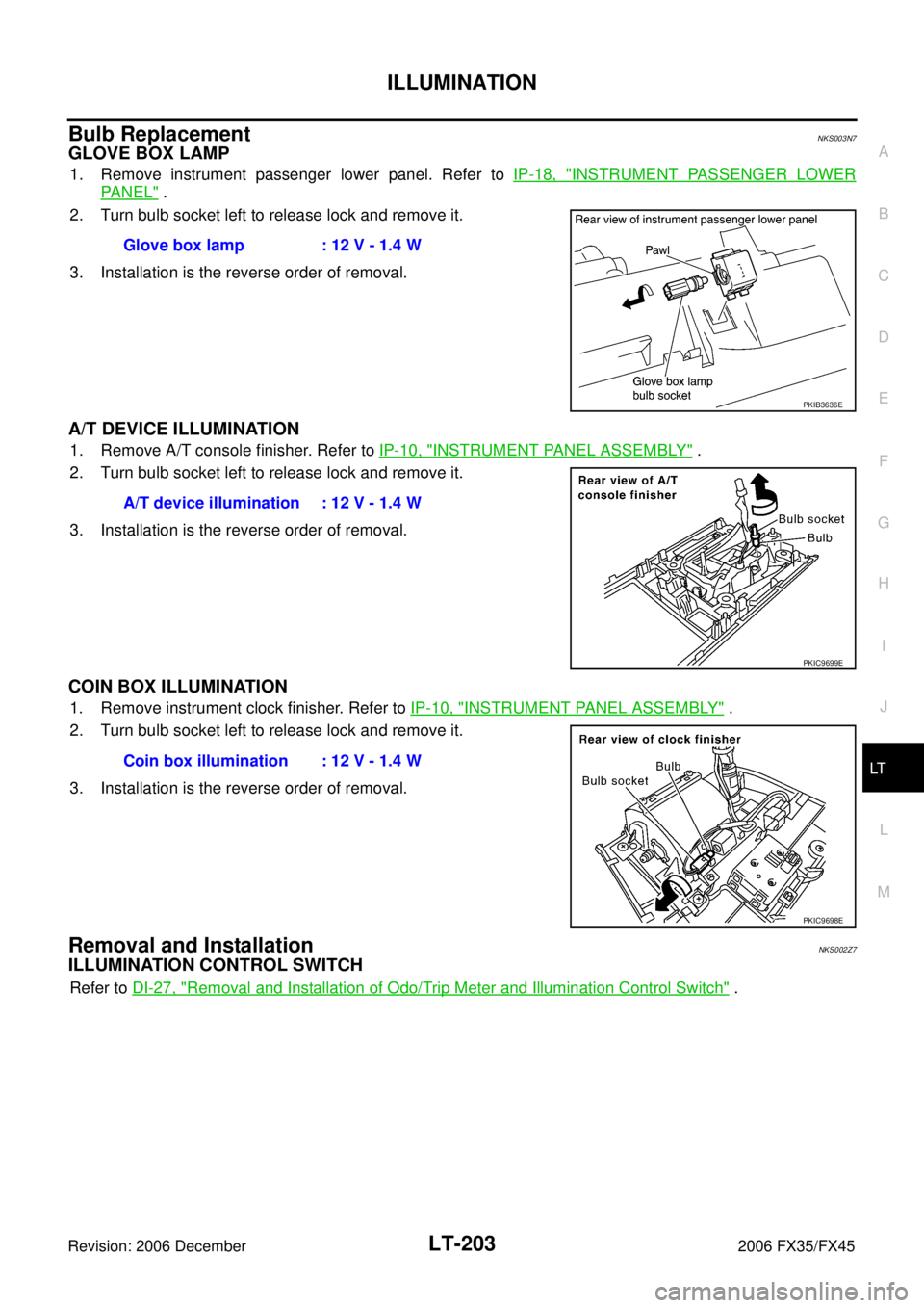
GLOVE BOX LAMP
1. Remove instrument passenger lower panel. Refer to IP-18, "INSTRUMENT PASSENGER LOWER
PA N E L" .
2. Turn bulb socket left to release lock and remove it.
3. Installation is the reverse order of removal.
A/T DEVICE ILLUMINATION
1. Remove A/T console finisher. Refer to IP-10, "INSTRUMENT PANEL ASSEMBLY" .
2. Turn bulb socket left to release lock and remove it.
3. Installation is the reverse order of removal.
COIN BOX ILLUMINATION
1. Remove instrument clock finisher. Refer to IP-10, "INSTRUMENT PANEL ASSEMBLY" .
2. Turn bulb socket left to release lock and remove it.
3. Installation is the reverse order of removal.
Removal and InstallationNKS002Z7
ILLUMINATION CONTROL SWITCH
Refer to DI-27, "Removal and Installation of Odo/Trip Meter and Illumination Control Switch" .
Glove box lamp : 12 V - 1.4 W
PKIB3636E
A/T device illumination : 12 V - 1.4 W
PKIC9699E
Coin box illumination : 12 V - 1.4 W
PKIC9698E
Page 3767 of 4462
LU-1
ENGINE LUBRICATION SYSTEM
B ENGINE
CONTENTS
C
D E
F
G H
I
J
K L
M
SECTION LU
A
LU
Revision: 2006 December 2006 FX35/FX45
ENGINE LUBRICATION SYSTEM
VQ35DE
PRECAUTIONS ..................................................... ..... 3
Precautions for Liquid Gasket ............................. ..... 3
LIQUID GASKET APPLICATION PROCEDURE ..... 3
PREPARATION ...................................................... ..... 4
Special Service Tools .......................................... ..... 4
Commercial Service Tools ................................... ..... 4
LUBRICATION SYSTEM ....................................... ..... 5
Lubrication Circuit ............................................... ..... 5
System Chart ...................................................... ..... 6
ENGINE OIL .......................................................... ..... 7
Inspection ............................................................ ..... 7
ENGINE OIL LEVEL ........................................ ..... 7
ENGINE OIL APPEARANCE ........................... ..... 7
ENGINE OIL LEAKAGE ................................... ..... 7
OIL PRESSURE CHECK ................................. ..... 8
Changing Engine Oil ........................................... ..... 9
OIL FILTER ............................................................ ... 10
Removal and Installation ..................................... ... 10
REMOVAL ........................................................ ... 10
INSTALLATION ................................................ ... 10
INSPECTION AFTER INSTALLATION ............ ... 10
OIL FILTER BRACKET (AWD) .............................. ... 12
Components ........................................................ ... 12
Removal and Installation ..................................... ... 12
REMOVAL ........................................................ ... 12
INSTALLATION ................................................ ... 12
INSPECTION AFTER INSTALLATION ............ ... 13
OIL COOLER ......................................................... ... 14
Components ........................................................ ... 14
Removal and Installation ..................................... ... 15
REMOVAL ........................................................ ... 15
INSPECTION AFTER REMOVAL .................... ... 16
INSTALLATION ................................................ ... 16
INSPECTION AFTER INSTALLATION ............ ... 16
OIL PUMP .............................................................. ... 17
Components ........................................................ ... 17
Removal and Installation ..................................... ... 17 REMOVAL ........................................................
... 17
INSTALLATION ................................................ ... 17
INSPECTION AFTER INSTALLATION ............. ... 17
Disassembly and Assembly ................................. ... 17
DISASSEMBLY ................................................ ... 17
INSPECTION AFTER DISASSEMBLY ............. ... 18
ASSEMBLY ...................................................... ... 19
SERVICE DATA AND SPECIFICATIONS (SDS) ... ... 20
Standard and Limit ............................................... ... 20
ENGINE OIL PRESSURE ................................ ... 20
ENGINE OIL CAPACITY (APPROXIMATE) ..... ... 20
OIL PUMP ........................................................ ... 20
REGULATOR VALVE ....................................... ... 20
VK45DE
PRECAUTIONS ..................................................... ... 21
Precautions for Liquid Gasket ............................. ... 21
LIQUID GASKET APPLICATION PROCEDURE ... 21
PREPARATION ...................................................... ... 22
Special Service Tools .......................................... ... 22
Commercial Service Tools ................................... ... 22
LUBRICATION SYSTEM ....................................... ... 23
Lubrication Circuit ................................................ ... 23
System Chart ....................................................... ... 24
ENGINE OIL ........................................................... ... 25
Inspection ............................................................ ... 25
ENGINE OIL LEVEL ......................................... ... 25
ENGINE OIL APPEARANCE ........................... ... 25
ENGINE OIL LEAKAGE ................................... ... 25
OIL PRESSURE CHECK ................................. ... 25
Changing Engine Oil ............................................ ... 27
OIL FILTER ............................................................ ... 28
Removal and Installation ..................................... ... 28
REMOVAL ........................................................ ... 28
INSTALLATION ................................................ ... 28
INSPECTION AFTER INSTALLATION ............. ... 28
Page 3768 of 4462

LU-2Revision: 2006 December 2006 FX35/FX45
OIL COOLER .........................................................
... 29
Components ........................................................ ... 29
Removal and Installation ..................................... ... 29
REMOVAL ........................................................ ... 29
INSPECTION AFTER REMOVAL ..................... ... 30
INSTALLATION ................................................. ... 30
INSPECTION AFTER INSTALLATION ............. ... 30
OIL PUMP .............................................................. ... 31
Components ........................................................ ... 31
Removal and Installation ..................................... ... 31
REMOVAL ........................................................ ... 31
INSTALLATION ................................................. ... 31 INSPECTION AFTER INSTALLATION .............
... 32
Disassembly and Assembly ................................. ... 32
DISASSEMBLY ................................................. ... 32
INSPECTION AFTER DISASSEMBLY ............. ... 32
ASSEMBLY ....................................................... ... 33
SERVICE DATA AND SPECIFICATIONS (SDS) ... ... 34
Standard and Limit ............................................... ... 34
OIL PRESSURE ............................................... ... 34
ENGINE OIL CAPACITY (APPROXIMATE) ..... ... 34
OIL PUMP ......................................................... ... 34
REGULATOR VALVE ........................................ ... 34