Page 3828 of 4462
MA-28
ENGINE MAINTENANCE (VK45DE ENGINE)
Revision: 2006 December 2006 FX35/FX45
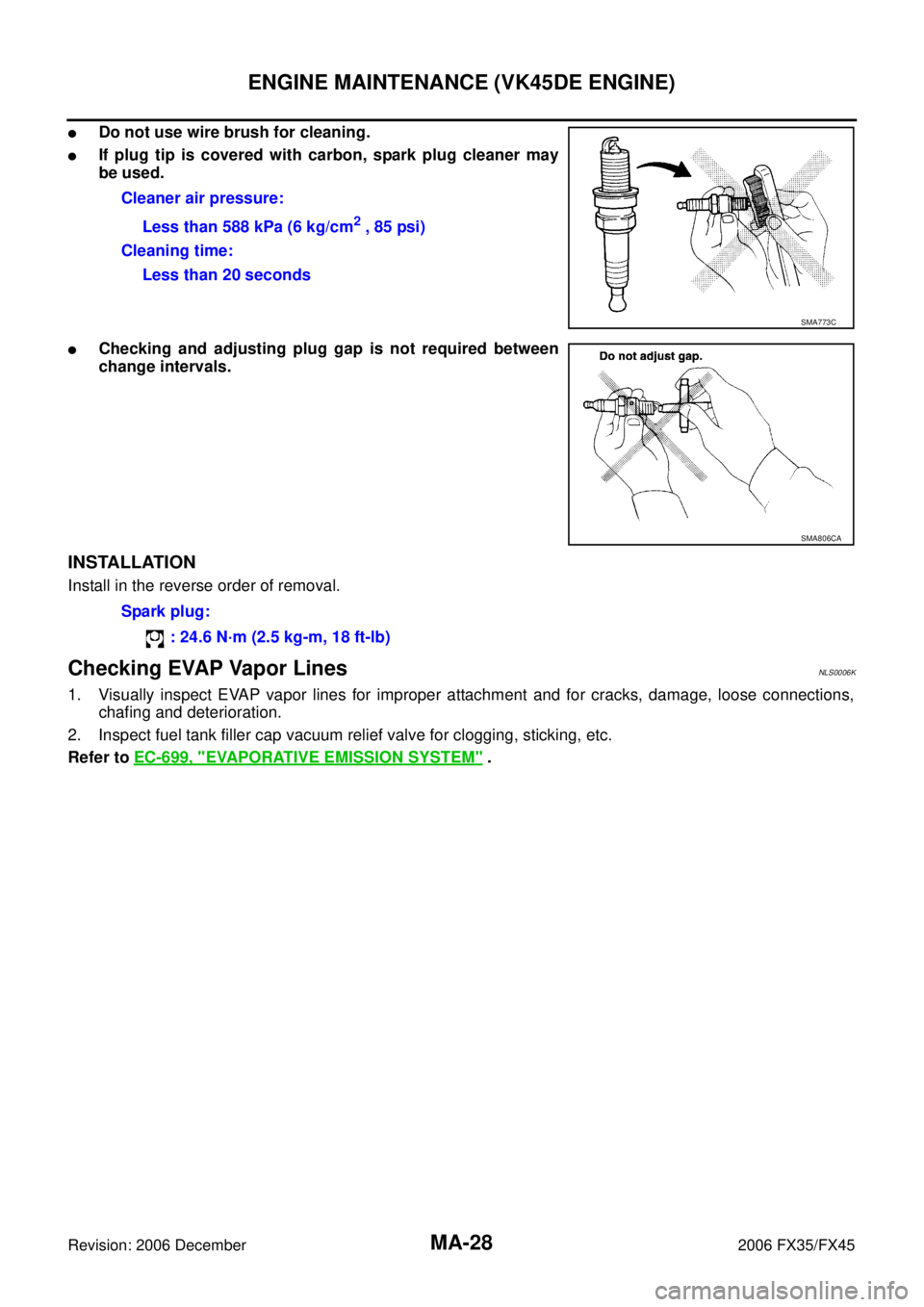
�Do not use wire brush for cleaning.
�If plug tip is covered with carbon, spark plug cleaner may
be used.
�Checking and adjusting plug gap is not required between
change intervals.
INSTALLATION
Install in the reverse order of removal.
Checking EVAP Vapor LinesNLS0006K
1. Visually inspect EVAP vapor lines for improper attachment and for cracks, damage, loose connections, chafing and deterioration.
2. Inspect fuel tank filler cap vacuum relief valve for clogging, sticking, etc.
Refer to EC-699, "
EVAPORATIVE EMISSION SYSTEM" .
Cleaner air pressure:
Less than 588 kPa (6 kg/cm
2 , 85 psi)
Cleaning time: Less than 20 seconds
SMA773C
SMA806CA
Spark plug:
: 24.6 N·m (2.5 kg-m, 18 ft-lb)
Page 3833 of 4462

CHASSIS AND BODY MAINTENANCE MA-33
C
D E
F
G H
I
J
K
M A
B
MA
Revision: 2006 December 2006 FX35/FX45
Changing Differential Gear OilNLS0006S
1. Drain oil from drain plug and refill with new gear oil.
2. Check oil level.
Balancing Wheels (Bonding Weight Type)NLS0006T
REMOVAL
1. Remove inner and outer balance weights from the road wheel. CAUTION:
Be careful not to scratch the road wheel during removal.
2. Using releasing agent, remove double-faced adhesive tape from the road wheel. CAUTION:
�Be careful not to scratch the road wheel during removal.
�After removing double-faced adhesive tape, wipe clean traces of releasing agent from the road
wheel.
WHEEL BALANCE ADJUSTMENT
�If a tire balance machine has adhesion balance weight mode settings and drive-in weight mode setting,
select and adjust a drive-in weight mode suitable for road wheels.
1. Set road wheel on tire balance machine using the center hole as a guide. Start the tire balance machine.
2. When inner and outer unbalance values are shown on the tire balance machine indicator, multiply outer unbalance value by 5/3 to determine balance weight that should be used. Select the outer balance weight
with a value closest to the calculated value above and install it to the designated outer position of, or at the
designated angle in relation to the road wheel.
CAUTION:
�Do not install the inner balance weight before installing the outer balance weight. Oil grade and Viscosity:
Refer to MA-12, "
RECOMMENDED FLUIDS
AND LUBRICANTS" .
Capacity:
Front final drive (F160A)
0.65 (1 - 3/8 US pt, 1 - 1/8 lmp pt)
Rear final drive (R200)
1.4 (3 US pt, 2 - 1/2 lmp pt)
Filler plug: Front final drive
: 34.5 N-m (3.5 kg-m, 25 ft-lb)
Rear final drive
: 34.5 N-m (3.5 kg-m, 25 ft-lb)
Drain plug: Front final drive
: 34.5 N-m (3.5 kg-m, 25 ft-lb)
Rear final drive
: 34.5 N-m (3.5 kg-m, 25 ft-lb)
SDIA1151E
Page 3843 of 4462

PB-1
PARKING BRAKE SYSTEM
F BRAKES
CONTENTS
C
D E
G H
I
J
K L
M
SECTION PB
A
B
PB
Revision: 2006 December 2006 FX35/FX45
PARKING BRAKE SYSTEM
PREPARATION ...................................................... ..... 2
Commercial Service Tools ................................... ..... 2
PARKING BRAKE SYSTEM ................................. ..... 3
On-Vehicle Inspection ......................................... ..... 3
PEDAL STROKE .............................................. ..... 3
INSPECT COMPONENTS ............................... ..... 3
ADJUSTMENT ................................................. ..... 3
PARKING BRAKE CONTROL .............................. ..... 4
Components ........................................................ ..... 4
Removal and Installation ..................................... ..... 4
REMOVAL ........................................................ ..... 4
INSTALLATION ................................................ ..... 5 PARKING BRAKE SHOE ......................................
..... 6
Components ........................................................ ..... 6
Removal and Installation ..................................... ..... 6
REMOVAL ........................................................ ..... 6
INSPECTION AFTER REMOVAL .................... ..... 7
INSTALLATION ................................................ ..... 8
SERVICE DATA AND SPECIFICATIONS (SDS) ... ..... 9
Parking Drum Brake ............................................ ..... 9
Parking Brake Control ......................................... ..... 9
Page 3846 of 4462
")
PB-4
PARKING BRAKE CONTROL
Revision: 2006 December 2006 FX35/FX45
PARKING BRAKE CONTROLPFP:36010
ComponentsNFS000MQ
Removal and InstallationNFS000MR
REMOVAL
1. Remove front kicking plate (driver side). Refer to EI-39, "KICKING PLATE" .
2. Remove front body side welt (driver side). Refer to EI-37, "
BODY SIDE TRIM" .
3. Remove dash side finisher (driver side). Refer to EI-38, "
DASH SIDE FINISHER" .
4. Remove instrument lower panel (driver side). Refer to IP-13, "
(K) Instrument Driver Lower Panel" .
5. Remove adjusting nut.
6. Remove front cable installation bolts, nuts, and lock plate, then remove front cable from the vehicle.
7. Remove heat insulator between center tube and rear propeller shaft.
8. Remove exhaust center muffler. Refer to EX-4, "
Removal and Installation" .
9. Remove propeller shaft. Refer to PR-9, "
Removal and Installation" .
10. Remove rear disc caliper and disc rotors. Refer to BR-27, "
Removal and Installation of Brake Caliper
Assembly" .
11. Remove parking brake shoe, and remove rear cable from toggle lever. Refer to PB-6, "
PARKING BRAKE
SHOE" .
1. Device assembly 2. Spring insulator 3. Return spring
4. Lock plate 5. Front cable 6. Return spring
7. Rear left cable 8. Rear right cable 9. Pin
10. Adjusting nut
SFIA1943E
Page 3847 of 4462
PARKING BRAKE CONTROL PB-5
C
D E
G H
I
J
K L
M A
B
PB
Revision: 2006 December 2006 FX35/FX45
12. Remove right and left rear cables installation nuts, bolts, and remove right and left rear cable assembly from the vehicle.
INSTALLATION
1. Install in the reverse order of removal. Tighten the mounting bolts and nuts to the specified torque. Referto PB-4, "
Components" .
CAUTION:
Do not reuse adjusting nut after removing it.
2. Adjust parking brake. Refer to PB-3, "
ADJUSTMENT" .
Page 3848 of 4462
PB-6
PARKING BRAKE SHOE
Revision: 2006 December 2006 FX35/FX45
PARKING BRAKE SHOEPFP:44060
ComponentsNFS000MS
Removal and InstallationNFS000MT
REMOVAL
WARNING:
Clean brakes with a vacuum dust collector to minimize the hazard of air borne particles or other mate-
rials.
CAUTION:
�Remove wheel, and remove disc rotor with parking brake pedal completely released. Refer to BR-
27, "Removal and Installation of Brake Caliper Assembly" .
�When removing disc rotor, mark both disc rotor and wheel hub for alignment.
1. Remove rear tires from vehicle with a power tool.
2. Remove disc rotor with the parking brake pedal in the completely released position.
3. Remove disc rotor. If disc rotor cannot be removed, remove as follows:
a. Secure the disc rotor in place with wheel nuts and remove adjuster hole plug.
1. Back plate 2. Anchor block 3. Toggle lever
4. Shoe 5. Adjuster 6. Return spring
7. Anti-rattle spring 8. Retainer 9. Anti-rattle pin
SFIA1167E
Page 3849 of 4462

PARKING BRAKE SHOE PB-7
C
D E
G H
I
J
K L
M A
B
PB
Revision: 2006 December 2006 FX35/FX45
b. Using flat-bladed screwdriver, rotate adjuster in direction “B” to retract and loosen brake shoe.
4. Remove anti −rattle pins, retainers, anti −rattle springs, them
return springs.
5. Remove parking brake shoes, adjuster assembly, adjuster spring and toggle lever.
INSPECTION AFTER REMOVAL
Lining Thickness Inspection
�Check thickness of lining.
Drum Inner Diameter Inspection
�Check drum inner diameter.
Other Inspections
�Check the following:
–Shoe for excessive wear, damage, and peeling.
–Shoe sliding surface for excessive wear and damage.
–Anti-rattle pin for excessive wear and corrosion.
–Return spring for sagging.
�Check that adjuster moves smoothly.
�Visually check the inside of drum for excessive wear, cracks, and damage. Check the inside of drum using
a pair of vernier calipers.
�Replace with new part if malfunction is detected on the above part.
�When disassembling adjuster, apply PBC (Poly Butyl Cuprysil) grease or equivalent to the threads. Refer
to PB-6, "
Components" .
PFIA0309E
Standard thickness “A” : 3.2 mm (0.126 in)
Repair limit thickness “A” : 1.5 mm (0.059 in)
SBR021A
Standard inner diameter : 190 mm (7.48 in) dia.
Maximum inner diameter : 191 mm (7.52 in) dia.
SBR768A
Page 3850 of 4462

PB-8
PARKING BRAKE SHOE
Revision: 2006 December 2006 FX35/FX45
INSTALLATION
Be careful of the following:
�Refer to PB-6, "Components" , and apply brake grease to the specified points during assembly.
�Assemble adjuster so that threaded part expands when rotating
it in the direction shown by the arrow.
�Shorten adjuster by rotating it.
�When disassembling adjuster, apply PBC (Poly Butyl Cuprysil)
grease or silicone based grease to the threads.
�After replacing brake shoes or disc rotors, or if brakes do not
function well, perform break-in operation as follows.
1. Install in the reverse order of the removal.
2. Adjust parking brake pedal stroke to the specified stroke. Refer to PB-3, "
ADJUSTMENT" .
3. Perform parking brake break-in (drag run) operation by driving the vehicle under the following conditions:
4. After break-in operation, check pedal stroke of parking brake. Readjust if it is no longer at the specified stroke. Refer to PB-3, "
ADJUSTMENT" .
�To prevent lining from getting too hot, allow a cool off period of approximately 5 minutes after every
break-in operation.
�Do not perform excessive break-in operations, because it may cause uneven or early wear of lining. Drive forward
�Perform the following
�Vehicle speed approx. 40 km/h (25 MPH) set (forward)
�Parking brake operating force approx. 200 N (20.4 kg, 44.9 lb) set
�Duration approx. 30sec.
SFIA0153E