2006 DODGE RAM SRT-10 clutch
[x] Cancel search: clutchPage 1358 of 5267
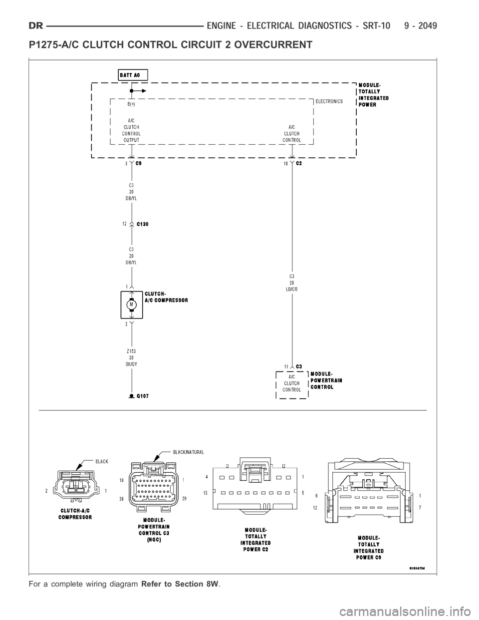
P1275-A/C CLUTCH CONTROL CIRCUIT 2 OVERCURRENT
For a complete wiring diagramRefer to Section 8W.
Page 1359 of 5267
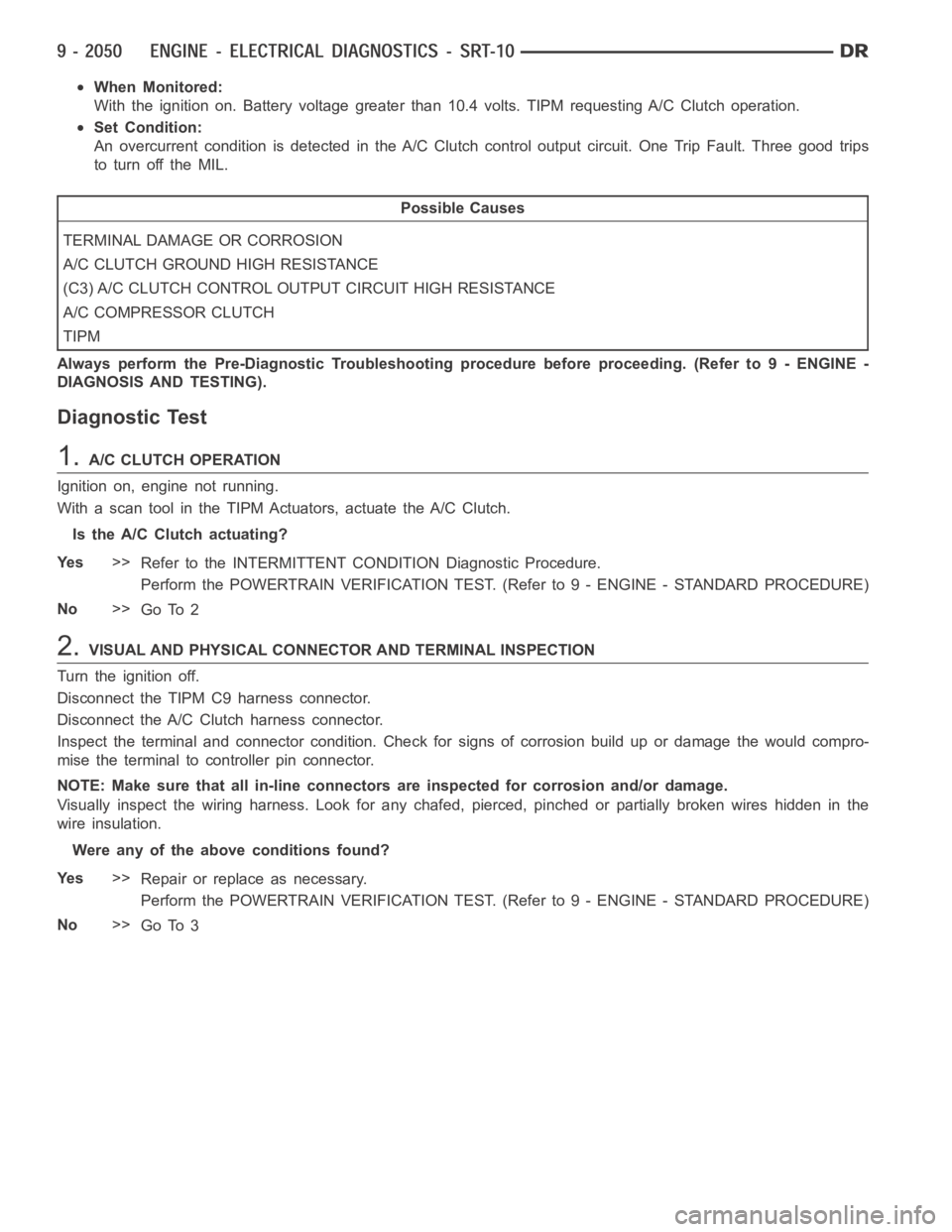
When Monitored:
With the ignition on. Battery voltage greater than 10.4 volts. TIPM requesting A/C Clutch operation.
Set Condition:
An overcurrent condition is detected in the A/C Clutch control output circuit. One Trip Fault. Three good trips
to turn off the MIL.
Possible Causes
TERMINAL DAMAGE OR CORROSION
A/C CLUTCH GROUND HIGH RESISTANCE
(C3) A/C CLUTCH CONTROL OUTPUT CIRCUIT HIGH RESISTANCE
A/C COMPRESSOR CLUTCH
TIPM
Always perform the Pre-Diagnostic Troubleshooting procedure before proceeding. (Refer to 9 - ENGINE -
DIAGNOSIS AND TESTING).
Diagnostic Test
1.A/C CLUTCH OPERATION
Ignition on, engine not running.
With a scan tool in the TIPM Actuators, actuate the A/C Clutch.
Is the A/C Clutch actuating?
Ye s>>
Refer to the INTERMITTENT CONDITION Diagnostic Procedure.
Perform the POWERTRAIN VERIFICATION TEST. (Refer to 9 - ENGINE - STANDARD PROCEDURE)
No>>
Go To 2
2.VISUAL AND PHYSICAL CONNECTOR AND TERMINAL INSPECTION
Turn the ignition off.
Disconnect the TIPM C9 harness connector.
Disconnect the A/C Clutch harness connector.
Inspect the terminal and connector condition. Check for signs of corrosion build up or damage the would compro-
mise the terminal to controller pin connector.
NOTE: Make sure that all in-line connectors are inspected for corrosion and/or damage.
Visually inspect the wiring harness. Look for any chafed, pierced, pinched or partially broken wires hidden in the
wire insulation.
Were any of the above conditions found?
Ye s>>
Repair or replace as necessary.
Perform the POWERTRAIN VERIFICATION TEST. (Refer to 9 - ENGINE - STANDARD PROCEDURE)
No>>
Go To 3
Page 1360 of 5267
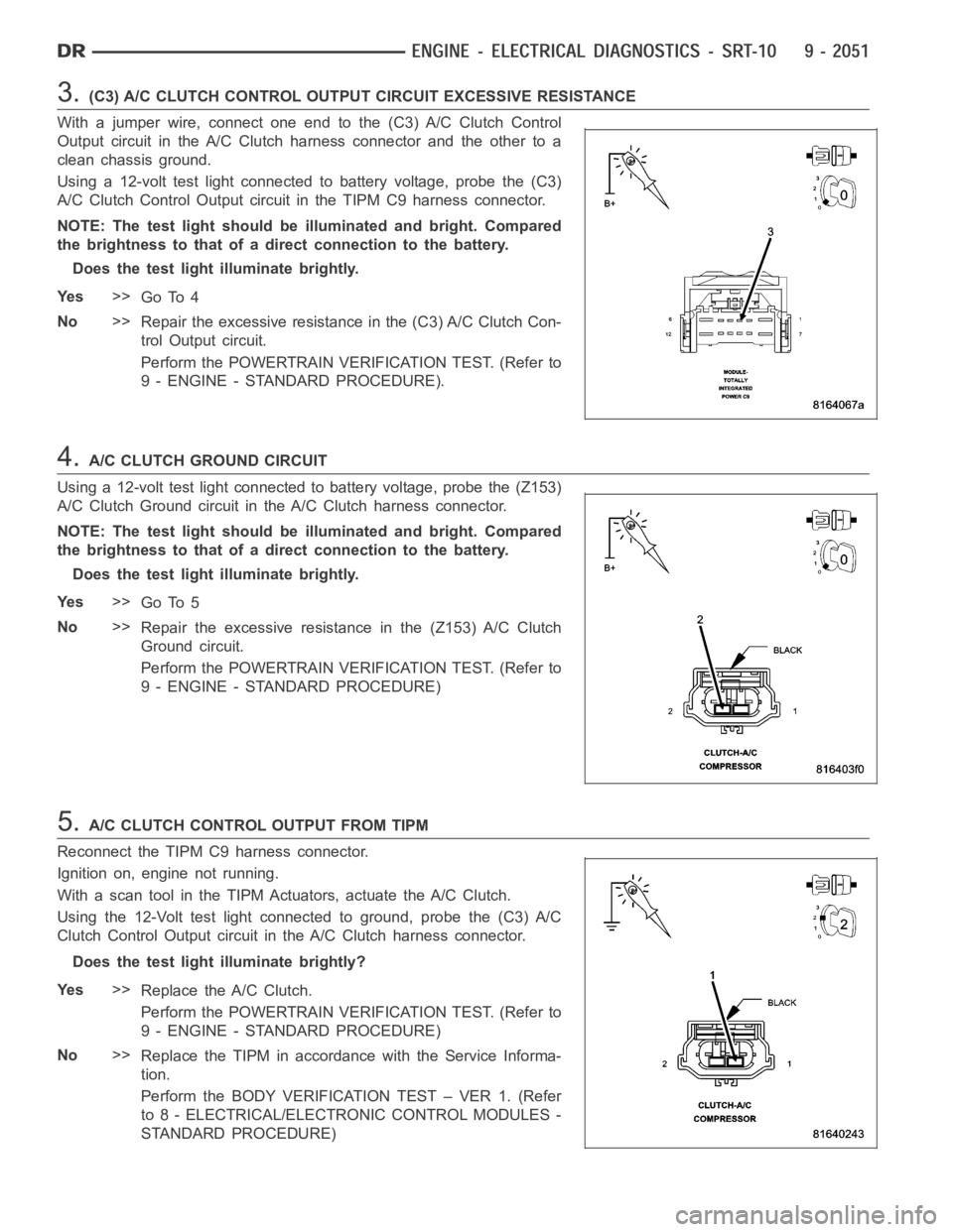
3.(C3) A/C CLUTCH CONTROL OUTPUT CIRCUIT EXCESSIVE RESISTANCE
With a jumper wire, connect one end to the (C3) A/C Clutch Control
Output circuit in the A/C Clutch harness connector and the other to a
clean chassis ground.
Using a 12-volt test light connected to battery voltage, probe the (C3)
A/C Clutch Control Output circuit in the TIPM C9 harness connector.
NOTE: The test light should be illuminated and bright. Compared
the brightness to that of a direct connection to the battery.
Does the test light illuminate brightly.
Ye s>>
Go To 4
No>>
Repair the excessive resistance in the (C3) A/C Clutch Con-
trol Output circuit.
Perform the POWERTRAIN VERIFICATION TEST. (Refer to
9 - ENGINE - STANDARD PROCEDURE).
4.A/C CLUTCH GROUND CIRCUIT
Using a 12-volt test light connected to battery voltage, probe the (Z153)
A/C Clutch Ground circuit in the A/C Clutch harness connector.
NOTE: The test light should be illuminated and bright. Compared
the brightness to that of a direct connection to the battery.
Does the test light illuminate brightly.
Ye s>>
Go To 5
No>>
Repair the excessive resistance in the (Z153) A/C Clutch
Ground circuit.
Perform the POWERTRAIN VERIFICATION TEST. (Refer to
9 - ENGINE - STANDARD PROCEDURE)
5.A/C CLUTCH CONTROL OUTPUT FROM TIPM
Reconnect the TIPM C9 harness connector.
Ignition on, engine not running.
With a scan tool in the TIPM Actuators, actuate the A/C Clutch.
Using the 12-Volt test light connected to ground, probe the (C3) A/C
Clutch Control Output circuit in the A/C Clutch harness connector.
Does the test light illuminate brightly?
Ye s>>
Replace the A/C Clutch.
Perform the POWERTRAIN VERIFICATION TEST. (Refer to
9 - ENGINE - STANDARD PROCEDURE)
No>>
Replace the TIPM in accordance with the Service Informa-
tion.
Perform the BODY VERIFICATION TEST – VER 1. (Refer
to 8 - ELECTRICAL/ELECTRONIC CONTROL MODULES -
STANDARD PROCEDURE)
Page 1469 of 5267
Possible Causes
A/C SELECT CIRCUIT OPEN
A/C SELECT IN HVAC
PCM
A/C REQUEST CIRCUIT OPEN
REFRIGERATION SYSTEM NOT PROPERLY CHARGED
HIGH PRESS CUT-OFF SWITCH
LOW PRESSURE SWITCH
A/CCLUTCHCOIL
A/C COMPRESSOR CLUTCH GROUND CIRCUIT OPEN
(C3) A/C CLUTCH RELAY OUTPUT CIRCUIT OPEN
FUSED B+ CIRCUIT OPEN
A/CCLUTCHRELAY
Always perform the Pre-Diagnostic Troubleshooting procedure before proceeding. (Refer to 9 - ENGINE -
DIAGNOSIS AND TESTING)
Diagnostic Test
1.DTC AND COMMUNICATION PRESENT
Ignition on, engine not running.
Verify that communication with the HVAC and PCM is available over the BUS.
With the scan tool, check for DTCs in the PCM and HVAC module.
Are any A/C DTC’s or communication failures present?
Ye s>>
Diagnose the related DTC(s) or BUS failure before continuing.
Perform BODY VERIFICATION TEST - VER 1.
No>>
Go To 2
2.A/C SELECT CIRCUIT OPEN
Engine running.
With the scan tool, read the A/C Select status in the PCM.
Turn the A/C Switch on and off a few times.
Does the A/C Select state change?
Ye s>>
Go To 3
No>>
Go To 12
3.A/C REQUEST CIRCUIT OPEN
Engine Running.
Turn the A/C system on and the fan on high.
With the scan tool in Inputs/Outputs, read the A/C request state.
Does the A/C request state change?
Ye s>>
Go To 4
No>>
Repair the open in the A/C Request circuit.
Perform BODY VERIFICATION TEST - VER 1.
Page 1470 of 5267
4.REFRIGERATION SYSTEM NOT PROPERLY CHARGED
Turn the ignition off.
Verify that the Refrigerant System is properly charged per Service Procedure.
Is the Refrigerant System properly charged?
Ye s>>
Go To 5
No>>
Properly charge the Refrigerant System per Service Information.
Perform BODY VERIFICATION TEST - VER 1.
5.HIGH PRESSURE CUT-OFF SWITCH
Turn the ignition off.
Verify the High Pressure Cut-Off Switch operation per Service Information.
Is the High Pressure Cut-Off Switch OK?
Ye s>>
Go To 6
No>>
Replace the High Pressure Cut-Off Switch.
Perform BODY VERIFICATION TEST - VER 1.
6.LOW PRESSURE SWITCH
Turn the ignition off.
Verify the Low Pressure Switch operation per Service Information.
Is the Low Pressure Switch OK?
Ye s>>
Go To 7
No>>
Replace the Low Pressure Switch.
Perform BODY VERIFICATION TEST - VER 1.
7.A/C CLUTCH COIL
Ignition on, engine not running.
Disconnect the A/C Compressor Clutch harness connector.
Connect a test light between the ground circuit and the A/C Clutch Relay Output circuit.
With the scan tool, actuate the A/C Clutch Relay.
Does the test light illuminate brightly on and off with the relay actuation?
Ye s>>
Replace the A/C Clutch Coil.
Perform BODY VERIFICATION TEST - VER 1.
No>>
Go To 8
8.A/C COMPRESSOR CLUTCH GROUND CIRCUIT OPEN
Turn the ignition off.
Disconnect the A/C Clutch harness connector.
NOTE: Check connectors - Clean/repair as necessary.
Measure the resistance between ground and the A/C Compressor Clutch ground circuit in the A/C Clutch harness
connector.
Is the resistance below 5.0 ohms?
Ye s>>
Go To 9
No>>
Repair the open in the A/C Compressor Clutch ground circuit.
Perform BODY VERIFICATION TEST - VER 1.
Page 1471 of 5267
9.(C3) A/C CLUTCH RELAY OUTPUT CIRCUIT OPEN
Turn the ignition off.
Disconnect the A/C Clutch harness connector.
Remove the A/C Clutch Relay.
NOTE: Check connectors - Clean/repair as necessary.
Measure the resistance of the (C3) A/C Clutch Relay Output circuit betweenthe IPM and the A/C Clutch Coil.
Is the resistance below 5.0 ohms?
Ye s>>
Go To 10
No>>
Repair the open in the (C3) A/C Clutch Relay Output circuit.
Perform BODY VERIFICATION TEST - VER 1.
10.(A17) FUSED B+ CIRCUIT OPEN
Turn the ignition off.
Remove the A/C Clutch Relay.
NOTE: Check connectors - Clean/repair as necessary.
Measure the voltage of the Fused B+ circuit at the A/C Clutch Relay connector.
Is the voltage above 11.0 volts?
Ye s>>
Go To 11
No>>
Repair the open in the Fused B+ circuit. The open may be in the IMP.
Perform BODY VERIFICATION TEST - VER 1.
11 .A/C CLUTCH RELAY
If there are no possible causes remaining, view repair.
Repair
Replace the A/C Clutch Relay.
Perform BODY VERIFICATION TEST - VER 1.
12.A/CSELECTSWITCHSTATUSINHVAC
Ignition on, engine not running.
With the scan tool in the HVAC, under the Monitors screen, read the A/C Select Switch state.
While monitoring the scan tool screen, turn the A/C switch on and off a few times.
Does the A/C Select State change on the HVAC Monitors screen.
Ye s>>
Check for any related TSBs. Replace and program the PCM in accordance with the Service Information
as long as no BUS problems exist.
Perform BODY VERIFICATION TEST - VER 1.
No>>
Replace the A/C-Heater Control module.
Perform BODY VERIFICATION TEST - VER 1.
Page 1564 of 5267
SEAL-CRANKSHAFT OIL-REAR
DIAGNOSIS AND TESTING - REAR SEAL AREA LEAKS
Since it is sometimes difficult to determine the source of an oil leak in therear seal area of the engine, a more
involved inspection is necessary. The following steps should be followedto help pinpoint the source of the leak.
If the leakage occurs at the crankshaft rear oil seal area:
1. Disconnect the battery.
2. Raise the vehicle.
3. Remove torque converter or clutch housing cover and inspect rear of block for evidence of oil. Use a black light
to check for the oil leak:
a. Circular spray pattern generally indicates seal leakage or crankshaftdamage.
b. Where leakage tends to run straight down, possible causes are a porous block, oil galley pipe plugs, oil filter
runoff, and main bearing cap to cylinder block mating surfaces. See Engine, for proper repair procedures of
these items.
4. If no leaks are detected, pressurized the crankcase as outlined in the section, Inspection (Engine oil Leaks in
general)
CAUTION: Do not exceed 20.6 kPa (3 psi).
5. If the leak is not detected, very slowly turn the crankshaft and watch forleakage. If a leak is detected between
the crankshaft and seal while slowly turning the crankshaft, it is possible the crankshaft seal surface is damaged.
The seal area on the crankshaft could have minor nicks or scratches that canbe polished out with emery cloth.
CAUTION: Use extreme caution when crankshaft polishing is necessary to remove minor nicks or
scratches. The crankshaft seal flange is specially machined to complement the function of the rear oil seal.
6. For bubbles that remain steady with shaft rotation, no further inspection can be done until disassembled. (Refer
to 9 - ENGINE - DIAGNOSIS AND TESTING), under the Oil Leak row, for components inspections on possible
causes and corrections.
7. After the oil leak root cause and appropriate corrective action have been identified, (Refer to 9 - ENGINE/EN-
GINE BLOCK/CRANKSHAFT OIL SEAL - REAR - REMOVAL).
REMOVAL
NOTE: This procedure can be performed in vehi-
cle.
1. If being performed in vehicle, remove the transmis-
sion.
2. Remove the flexplate (Refer to 9 - ENGINE/EN-
GINE BLOCK/FLEX PLATE - REMOVAL).
NOTE: The crankshaft oil seal CAN NOT be reused
after removal.
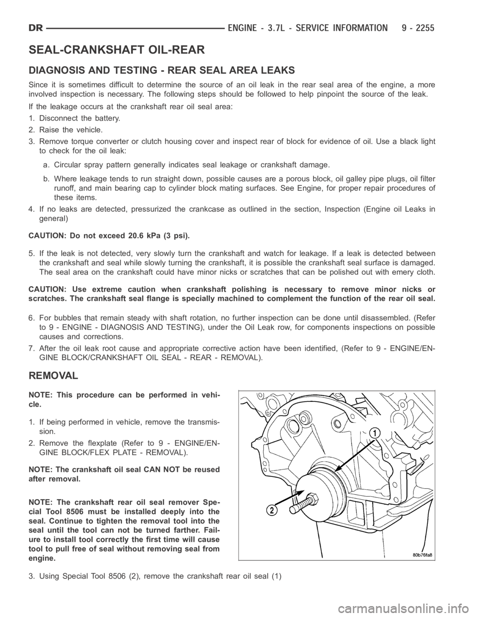
NOTE: The crankshaft rear oil seal remover Spe-
cial Tool 8506 must be installed deeply into the
seal. Continue to tighten the removal tool into the
seal until the tool can not be turned farther. Fail-
ure to install tool correctly the first time will cause
tool to pull free of seal without removing seal from
engine.
3. Using Special Tool 8506 (2), remove the crankshaft rear oil seal (1)
Page 1578 of 5267
INSTALLATION
CAUTION: To prevent severe damage to the Crank-
shaft, Damper or Special Tool 8512–A, thoroughly
clean the damper bore and the crankshaft nose
before installing Damper.
1. Align crankshaft damper slot with key in crankshaft.
Slide damper onto crankshaft slightly.
CAUTION: Special Tool 8512–A, is assembled in a
specific sequence. Failure to assemble this tool in
this sequence can result in tool failure and severe
damage to either the tool or the crankshaft.
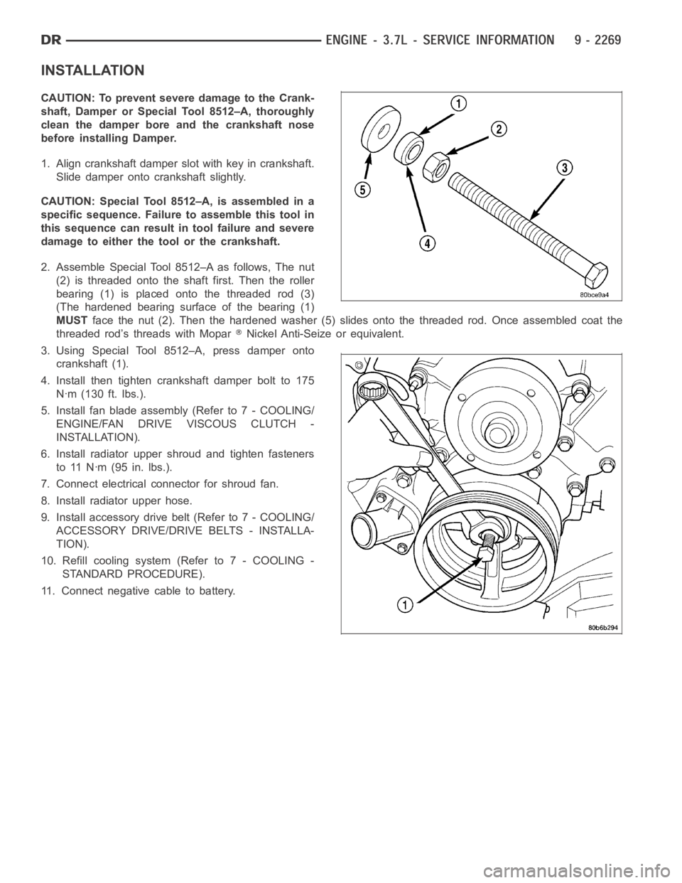
2. Assemble Special Tool 8512–A as follows, The nut
(2) is threaded onto the shaft first. Then the roller
bearing (1) is placed onto the threaded rod (3)
(The hardened bearing surface of the bearing (1)
MUSTface the nut (2). Then the hardened washer (5) slides onto the threaded rod.Once assembled coat the
threaded rod’s threads with Mopar
Nickel Anti-Seize or equivalent.
3. Using Special Tool 8512–A, press damper onto
crankshaft (1).
4. Install then tighten crankshaft damper bolt to 175
Nꞏm (130 ft. lbs.).
5. Install fan blade assembly (Refer to 7 - COOLING/
ENGINE/FAN DRIVE VISCOUS CLUTCH -
INSTALLATION).
6. Install radiator upper shroud and tighten fasteners
to 11 Nꞏm (95 in. lbs.).
7. Connect electrical connector for shroud fan.
8. Install radiator upper hose.
9. Install accessory drive belt (Refer to 7 - COOLING/
ACCESSORY DRIVE/DRIVE BELTS - INSTALLA-
TION).
10. Refill cooling system (Refer to 7 - COOLING -
STANDARD PROCEDURE).
11. Connect negative cable to battery.