Page 153 of 5267
7.PCM
NOTE: Before continuing, check the PCM harness connector terminals for corrosion, damage, or terminal
push out. Repair as necessary.
Using the schematics as a guide, inspect the wire harness and connectors. Pay particular attention to all Power and
Ground circuits.
Were there any problems found?
Ye s>>
Repair as necessary.
Perform the POWERTRAIN VERIFICATION TEST. (Refer to 9 - ENGINE - STANDARD PROCEDURE)
No>>
Replace and program the Powertrain Control Module per Service Information.
Perform the POWERTRAIN VERIFICATION TEST. (Refer to 9 - ENGINE - STANDARD PROCEDURE)
Page 157 of 5267

5.(F856) AUXILIARY 5-VOLT SUPPLY CIRCUIT SHORTED TO BATTERY VOLTAGE
Turn the ignition off.
Disconnect the C1 PCM harness connector.
Disconnect all the Sensors that share the (F856) Auxiliary 5-volt Supply
circuit.
Ignition on, engine not running.
Measure the voltage on the (F856) Auxiliary 5-volt Supply circuit at the
CMP Sensor harness connector.
Is the voltage above 0 volts?
Ye s>>
Repair the short to battery voltage in the (F856) Auxiliary
5-volt Supply circuit.
Perform the POWERTRAIN VERIFICATION TEST. (Refer to
9 - ENGINE - STANDARD PROCEDURE)
No>>
Go To 6
6.(F856) AUXILIARY 5-VOLT SUPPLY CIRCUIT OPEN
Turn the ignition off.
Reconnect all the sensors that were disconnected in the previous step
except the CMP Sensor harness connector.
CAUTION: Do not probe the PCM harness connectors. Probing the
PCM harness connectors will damage the PCM terminals resulting
in poor terminal to pin connection. Install Miller Special Tool #8815
to perform diagnosis.
Measure the resistance in the (F856) Auxiliary 5-volt Supply circuit from
the Sensor harness connector to the appropriate terminal of special tool
#8815.
It may be necessary to perform this test from every sensor that uses
the (F856) Auxiliary 5-volt Supply circuit.
Is the resistance below 5.0 ohms?
Ye s>>
Go To 7
No>>
Repair the open in the (F856) Auxiliary 5-volt Supply circuit.
Perform the POWERTRAIN VERIFICATION TEST. (Refer to
9 - ENGINE - STANDARD PROCEDURE)
7.PCM
NOTE: Before continuing, check the PCM harness connector terminals for corrosion, damage, or terminal
push out. Repair as necessary.
Using the schematics as a guide, inspect the wire harness and connectors. Pay particular attention to all Power and
Ground circuits.
Were there any problems found?
Ye s>>
Repair as necessary.
Perform the POWERTRAIN VERIFICATION TEST. (Refer to 9 - ENGINE - STANDARD PROCEDURE)
No>>
Replace and program the Powertrain Control Module per Service Information.
Perform the POWERTRAIN VERIFICATION TEST. (Refer to 9 - ENGINE - STANDARD PROCEDURE)
Page 158 of 5267

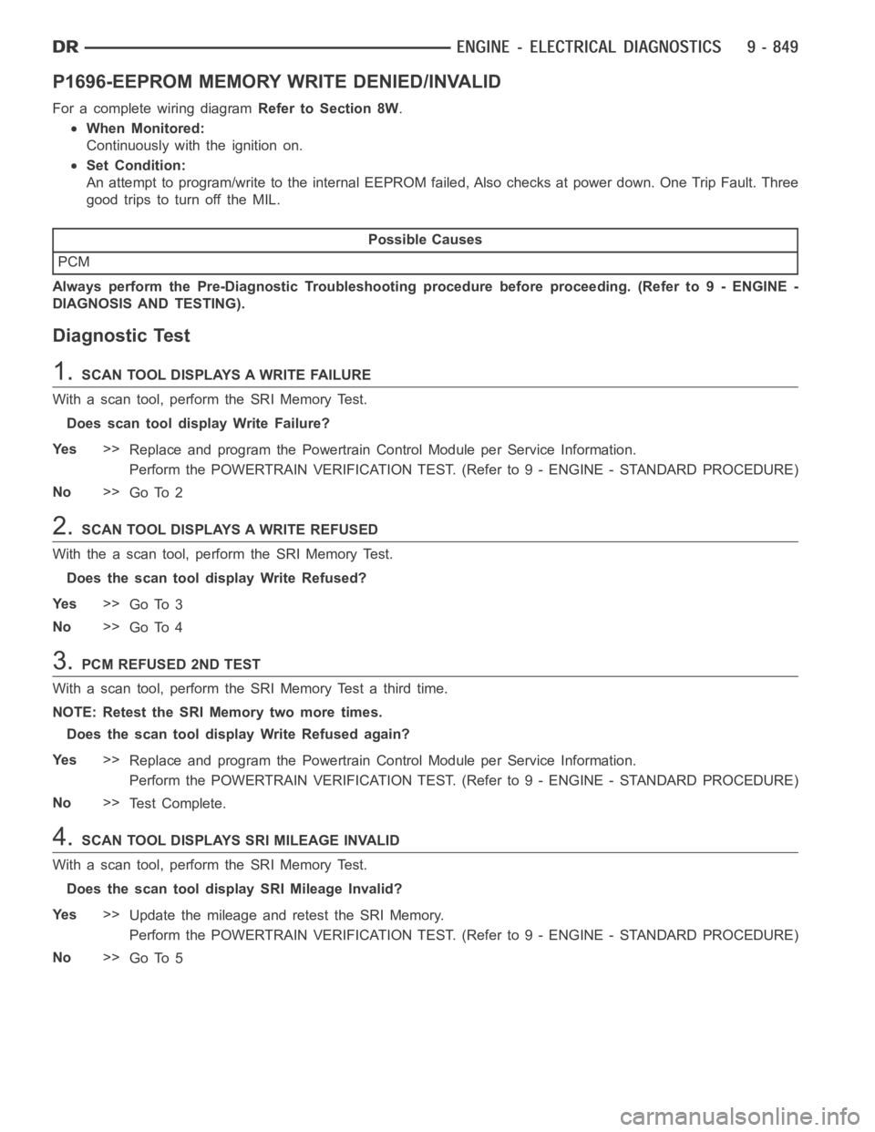
P1696-EEPROM MEMORY WRITE DENIED/INVALID
For a complete wiring diagramRefer to Section 8W.
When Monitored:
Continuously with the ignition on.
Set Condition:
An attempt to program/write to the internal EEPROM failed, Also checks at power down. One Trip Fault. Three
good trips to turn off the MIL.
Possible Causes
PCM
Always perform the Pre-Diagnostic Troubleshooting procedure before proceeding. (Refer to 9 - ENGINE -
DIAGNOSIS AND TESTING).
Diagnostic Test
1.SCAN TOOL DISPLAYS A WRITE FAILURE
With a scan tool, perform the SRI Memory Test.
Does scan tool display Write Failure?
Ye s>>
Replace and program the Powertrain Control Module per Service Information.
Perform the POWERTRAIN VERIFICATION TEST. (Refer to 9 - ENGINE - STANDARD PROCEDURE)
No>>
Go To 2
2.SCAN TOOL DISPLAYS A WRITE REFUSED
With the a scan tool, perform the SRI Memory Test.
Does the scan tool display Write Refused?
Ye s>>
Go To 3
No>>
Go To 4
3.PCM REFUSED 2ND TEST
With a scan tool, perform the SRI Memory Test a third time.
NOTE: Retest the SRI Memory two more times.
Does the scan tool display Write Refused again?
Ye s>>
Replace and program the Powertrain Control Module per Service Information.
Perform the POWERTRAIN VERIFICATION TEST. (Refer to 9 - ENGINE - STANDARD PROCEDURE)
No>>
Te s t C o m p l e t e .
4.SCAN TOOL DISPLAYS SRI MILEAGE INVALID
With a scan tool, perform the SRI Memory Test.
Does the scan tool display SRI Mileage Invalid?
Ye s>>
Update the mileage and retest the SRI Memory.
Perform the POWERTRAIN VERIFICATION TEST. (Refer to 9 - ENGINE - STANDARD PROCEDURE)
No>>
Go To 5
Page 160 of 5267

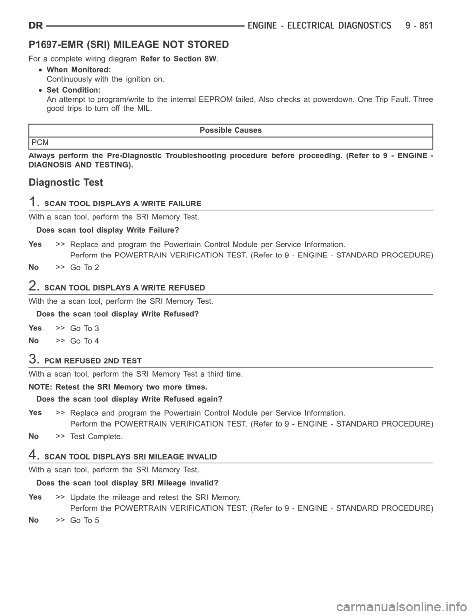
P1697-EMR (SRI) MILEAGE NOT STORED
For a complete wiring diagramRefer to Section 8W.
When Monitored:
Continuously with the ignition on.
Set Condition:
An attempt to program/write to the internal EEPROM failed, Also checks at powerdown. One Trip Fault. Three
good trips to turn off the MIL.
Possible Causes
PCM
Always perform the Pre-Diagnostic Troubleshooting procedure before proceeding. (Refer to 9 - ENGINE -
DIAGNOSIS AND TESTING).
Diagnostic Test
1.SCAN TOOL DISPLAYS A WRITE FAILURE
With a scan tool, perform the SRI Memory Test.
Does scan tool display Write Failure?
Ye s>>
Replace and program the Powertrain Control Module per Service Information.
Perform the POWERTRAIN VERIFICATION TEST. (Refer to 9 - ENGINE - STANDARD PROCEDURE)
No>>
Go To 2
2.SCAN TOOL DISPLAYS A WRITE REFUSED
With the a scan tool, perform the SRI Memory Test.
Does the scan tool display Write Refused?
Ye s>>
Go To 3
No>>
Go To 4
3.PCM REFUSED 2ND TEST
With a scan tool, perform the SRI Memory Test a third time.
NOTE: Retest the SRI Memory two more times.
Does the scan tool display Write Refused again?
Ye s>>
Replace and program the Powertrain Control Module per Service Information.
Perform the POWERTRAIN VERIFICATION TEST. (Refer to 9 - ENGINE - STANDARD PROCEDURE)
No>>
Te s t C o m p l e t e .
4.SCAN TOOL DISPLAYS SRI MILEAGE INVALID
With a scan tool, perform the SRI Memory Test.
Does the scan tool display SRI Mileage Invalid?
Ye s>>
Update the mileage and retest the SRI Memory.
Perform the POWERTRAIN VERIFICATION TEST. (Refer to 9 - ENGINE - STANDARD PROCEDURE)
No>>
Go To 5
Page 162 of 5267
P1897-LEVEL 1 RPM BUS UNLOCK
For a complete wiring diagramRefer to Section 8W.
When Monitored:
Engine running.
Set Condition:
When the PCM recognizes an internal failure to communicate with the FCM or the CMP and CKP Sensor
count periods are too short. One trip fault. ETC light is flashing.
Possible Causes
PCM
Always perform the Pre-Diagnostic Troubleshooting procedure before proceeding. (Refer to 9 - ENGINE -
DIAGNOSIS AND TESTING).
Diagnostic Test
1.PCM
NOTE: Diagnose any CMP or CKP Sensor faults before continuing. Check for intermittent loose CMP or CKP
connections.
The Powertrain Control Module is reporting internal errors, view repair to continue.
Repair
Replace and program the Powertrain Control Module per Service Information.
Perform the POWERTRAIN VERIFICATION TEST. (Refer to 9 - ENGINE - STANDARD PROCEDURE)
Page 173 of 5267
17.PCM
NOTE: Before continuing, check the PCM harness connector terminals for corrosion, damage, or terminal
push out. Repair as necessary.
Using the schematics as a guide, inspect the wire harness and connectors. Pay particular attention to all Power and
Ground circuits.
Were there any problems found?
Ye s>>
Repair as necessary.
Perform the POWERTRAIN VERIFICATION TEST. (Refer to 9 - ENGINE - STANDARD PROCEDURE)
No>>
Replace and program the Powertrain Control Module per Service Information.
Perform the POWERTRAIN VERIFICATION TEST. (Refer to 9 - ENGINE - STANDARD PROCEDURE)
Page 177 of 5267
5.(K141) O2 SENSOR 1/2 SIGNAL CIRCUIT
Remove the jump wire.
Ignition on, engine not running.
With the scan tool, monitor the 1/2 O2 Sensor voltage.
Is the voltage above 4.8 volts?
Ye s>>
Go To 6
No>>
Check the (K141) O2 Sensor 1/2 Signal circuit for an open
or short to voltage. Inspect the O2 Sensor connector and
the PCM harness connector. If OK, replace and program
the Powertrain Control Module per Service Information.
Perform the POWERTRAIN VERIFICATION TEST. (Refer to
9 - ENGINE - STANDARD PROCEDURE)
6.(K299) O2 SENSOR 1/2 HEATER CONTROL CIRCUIT SHORTED TO GROUND
Turn the ignition off.
Disconnect the C3 PCM harness connector.
Measure the resistance between ground and the (K299) O2 Sensor 1/2
Heater Control circuit from the O2 Sensor harness connector.
Is the resistance below 5.0 ohms?
Ye s>>
Repair the short to ground in the (K299) O2 Sensor 1/2
Heater Control circuit.
Perform the POWERTRAIN VERIFICATION TEST. (Refer to
9 - ENGINE - STANDARD PROCEDURE)
No>>
Go To 7
Page 178 of 5267
7.(K904) O2 RETURN DOWNSTREAM CIRCUIT
Measure the voltage on the (K904) O2 Return Downstream circuit in the
O2 Sensor harness connector.
Is the voltage at 2.5 volts?
Ye s>>
Check the fuel system for contaminants.
Perform the POWERTRAIN VERIFICATION TEST. (Refer to
9 - ENGINE - STANDARD PROCEDURE)
No>>
Check the (K904) O2 Return Downstream circuit for a short
to ground, open, or short to voltage. Inspect the O2 Sensor
connector and the PCM harness connector. If OK, replace
and program the Powertrain Control Module per Service
Information.
Perform the POWERTRAIN VERIFICATION TEST. (Refer to
9 - ENGINE - STANDARD PROCEDURE)