2006 DODGE RAM SRT-10 key battery
[x] Cancel search: key batteryPage 2424 of 5267
IGNITION SWITCH - SRT10
REMOVAL - SRT10
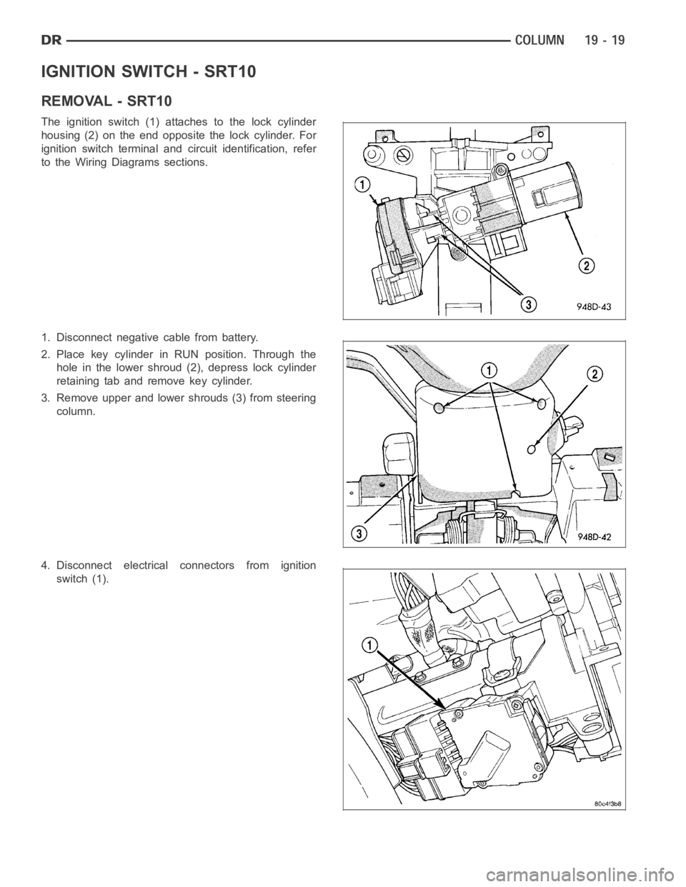
The ignition switch (1) attaches to the lock cylinder
housing (2) on the end opposite the lock cylinder. For
ignition switch terminal and circuit identification, refer
to the Wiring Diagrams sections.
1. Disconnect negative cable from battery.
2. Place key cylinder in RUN position. Through the
hole in the lower shroud (2), depress lock cylinder
retaining tab and remove key cylinder.
3. Remove upper and lower shrouds (3) from steering
column.
4. Disconnect electrical connectors from ignition
switch (1).
Page 2426 of 5267
INSTALLATION - SRT10
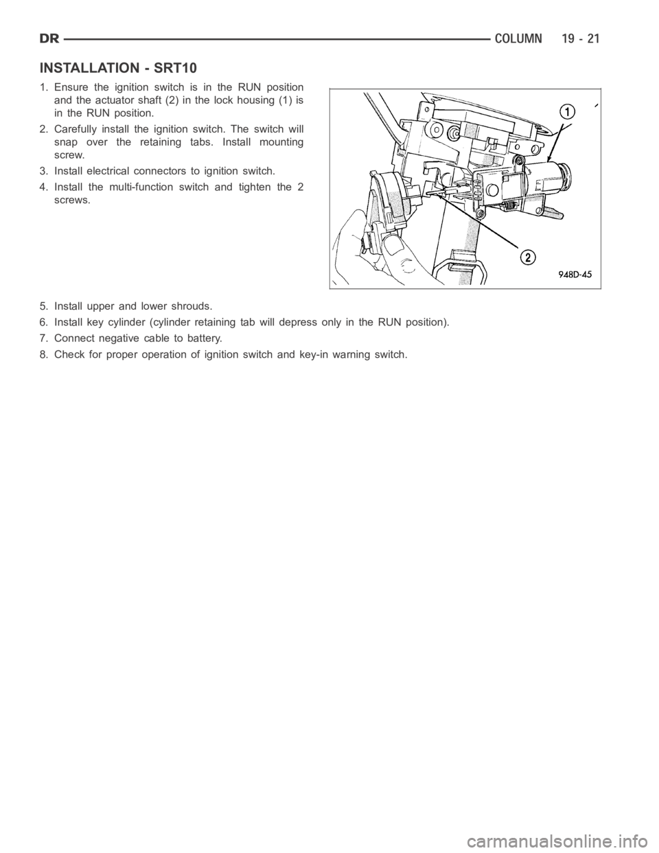
1. Ensure the ignition switch is in the RUN position
and the actuator shaft (2) in the lock housing (1) is
in the RUN position.
2. Carefully install the ignition switch. The switch will
snap over the retaining tabs. Install mounting
screw.
3. Install electrical connectors to ignition switch.
4. Install the multi-function switch and tighten the 2
screws.
5. Install upper and lower shrouds.
6. Install key cylinder (cylinder retaining tab will depress only in the RUN position).
7. Connect negative cable to battery.
8. Check for proper operation of ignition switch and key-in warning switch.
Page 2428 of 5267
KEY CYLINDER
REMOVAL
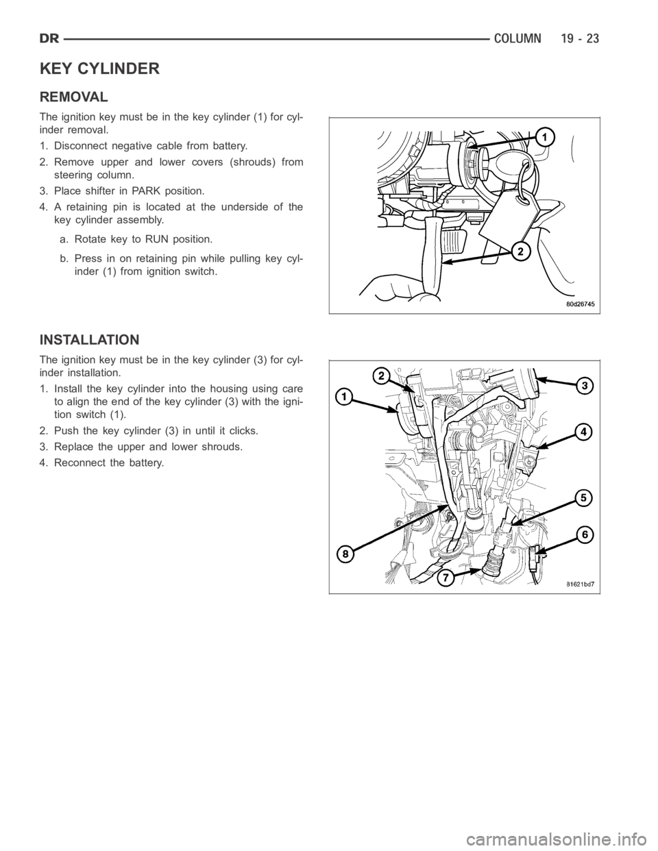
The ignition key must be in the key cylinder (1) for cyl-
inder removal.
1. Disconnect negative cable from battery.
2. Remove upper and lower covers (shrouds) from
steering column.
3. Place shifter in PARK position.
4. A retaining pin is located at the underside of the
key cylinder assembly.
a. Rotate key to RUN position.
b. Press in on retaining pin while pulling key cyl-
inder (1) from ignition switch.
INSTALLATION
The ignition key must be in the key cylinder (3) for cyl-
inder installation.
1. Install the key cylinder into the housing using care
to align the end of the key cylinder (3) with the igni-
tion switch (1).
2. Push the key cylinder (3) in until it clicks.
3. Replace the upper and lower shrouds.
4. Reconnect the battery.
Page 2437 of 5267
UPPER STEERING COUPLING
REMOVAL
1. Disconnect the negative battery cable.
NOTE: The steering column on vehicles with an automatic transmission may not be equipped with an inter-
nal locking shaft that allows the ignition key cylinder to be locked with the key. Alternative methods of lock-
ing the steering wheel for service will have to be used.
2. Lock the steering wheel with the tire in the straight position.
3. Remove and discard the lower pinch bolt.
4. Lower the steering coupler shaft from the column.
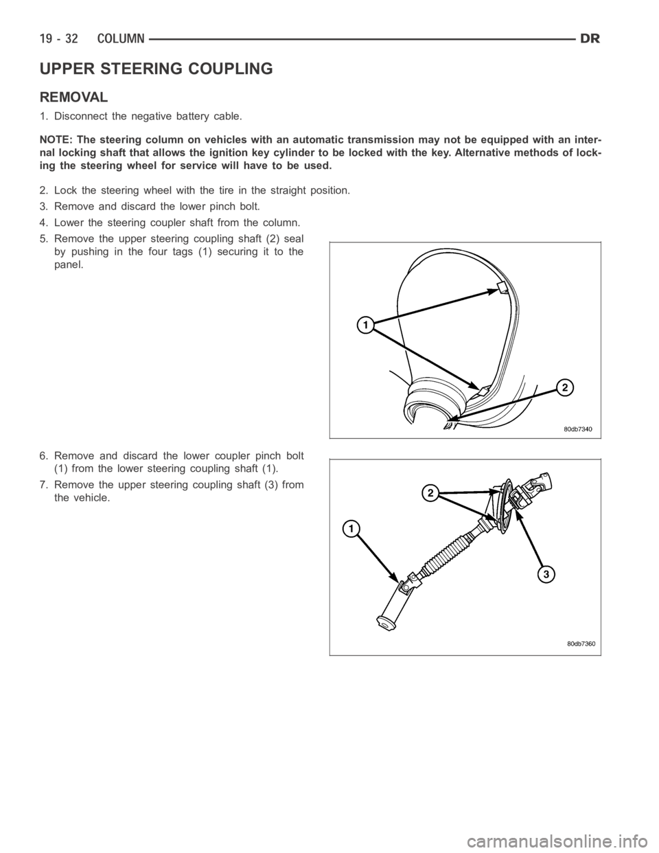
5. Remove the upper steering coupling shaft (2) seal
by pushing in the four tags (1) securing it to the
panel.
6. Remove and discard the lower coupler pinch bolt
(1) from the lower steering coupling shaft (1).
7. Remove the upper steering coupling shaft (3) from
the vehicle.
Page 2439 of 5267
LOWER STEERING COUPLING
REMOVAL
ALLLD&HDEXCEPT4X4HD
1. Disconnect the negative battery cable.
2. Raise and support the vehicle.
NOTE: The steering column on vehicles with an automatic transmission may not be equipped with an inter-
nal locking shaft that allows the ignition key cylinder to be locked with the key. Alternative methods of lock-
ing the steering wheel for service will have to be used.
3. Lock the steering wheel with the tire in the straight position.
4. Remove the left front tire and wheel assembly.
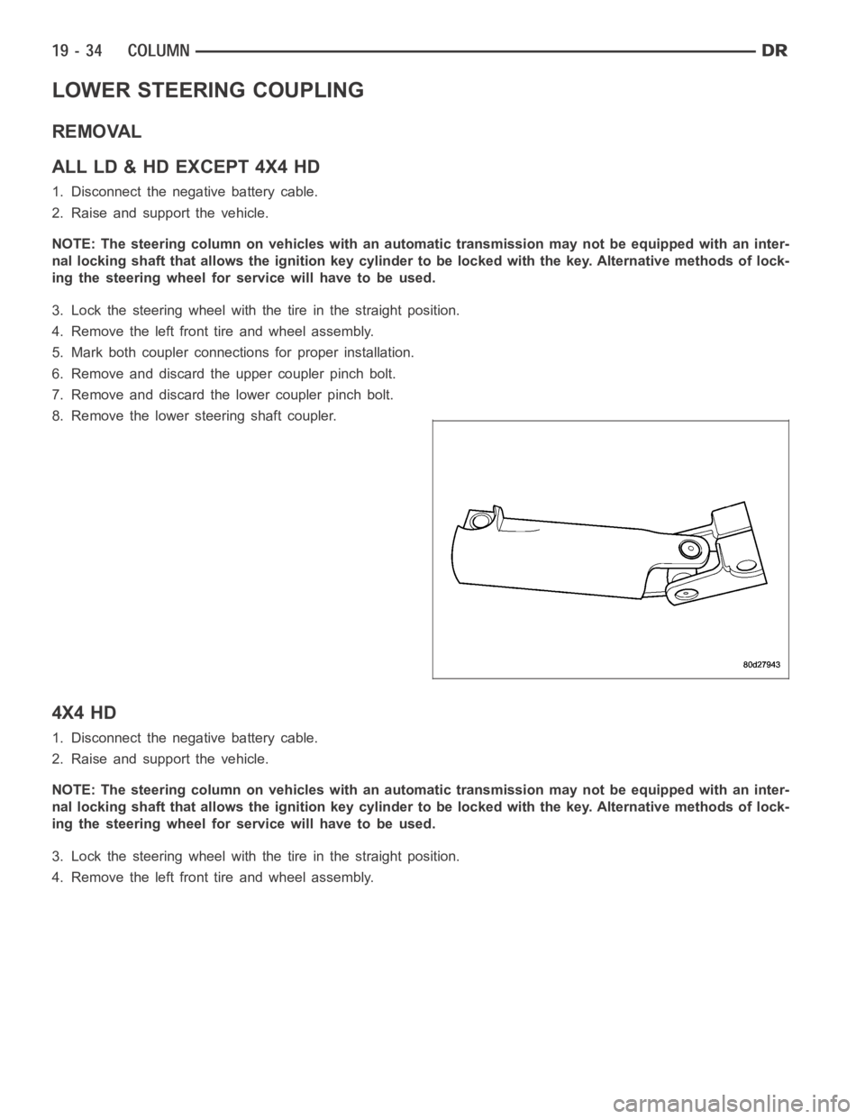
5. Mark both coupler connections for proper installation.
6. Remove and discard the upper coupler pinch bolt.
7. Remove and discard the lower coupler pinch bolt.
8. Remove the lower steering shaft coupler.
4X4 HD
1. Disconnect the negative battery cable.
2. Raise and support the vehicle.
NOTE: The steering column on vehicles with an automatic transmission may not be equipped with an inter-
nal locking shaft that allows the ignition key cylinder to be locked with the key. Alternative methods of lock-
ing the steering wheel for service will have to be used.
3. Lock the steering wheel with the tire in the straight position.
4. Remove the left front tire and wheel assembly.
Page 2847 of 5267
When Monitored:
One time after a reset (ignition key turned to the RUN position or after cranking engine).
Set Condition:
A fault is set if voltage greater than 4.5 volts is detected for 7 msec on any of the pressure switch circuits
before the relay is energized. The transmission is placed in Limp-In. The MIL is on after 10 seconds. of vehicle
operation.
Possible Causes
(T47) 2/4 PRESSURE SWITCH SENSE CIRCUIT SHORT TO VOLTAGE
(T50) L/R PRESSURE SWITCH SENSE CIRCUIT SHORT TO VOLTAGE
(T9) OD PRESSURE SWITCH SENSE CIRCUIT SHORT TO VOLTAGE
POWERTRAIN CONTROL MODULE
Always perform the 42RLE Pre-Diagnostic Troubleshooting procedure before proceeding. (Refer to 21 -
TRANSMISSION/TRANSAXLE/AUTOMATIC - 42RLE - STANDARD PROCEDURE)
Theory of Operation
The transmission relay is used to supply power to the solenoid pack when in normal operating mode and to turn off
power to produce transmission
limp-inmode. The relay output (which supplies power to the solenoid pack) is fed
back to the controller. It is referred to as SWITCHED BATTERY. After a controller reset (ignition key turned to the
RUN position or after cranking engine), the controller verifies that the relay contacts are open by checking for no
voltage on Switched battery line (transmission control relay output) before the relay is energized. After switched
battery is verified for no voltage, the voltage of each of the solenoid packpressure switches is also checked. Since
the solenoid pack is not powered up, there should be no voltage on any of the pressure switches.
Diagnostic Test
1.CHECK TO SEE IF DTC P0890 IS PRESENT
With the scan tool, view DTCs.
Is the status Active for this DTC or is the STARTS SINCE SET counter set at 0?
Ye s>>
Go To 2
No>>
Go To 5
Page 2881 of 5267
When Monitored:
After a reset (ignition key turned to the RUN position).
Set Condition:
The checksum of the battery backed RAM does not match the stored checksum. Set Time: Less than 7 msec.
Possible Causes
BATTERY WAS DISCONNECTED
PCM WAS REPLACED OR DISCONNECTED
QUICK LEARN WAS PERFORMED
(A919) FUSED B+ CIRCUIT TO PCM OPEN
(Z908 and Z977) GROUND CIRCUIT OPEN
Always perform the 42RLE Pre-Diagnostic Troubleshooting procedure before proceeding. (Refer to 21 -
TRANSMISSION/TRANSAXLE/AUTOMATIC - 42RLE - STANDARD PROCEDURE)
Theory of Operation
Note: This is not a fault code. It exists to provide reference information only. A battery backed RAM is used to
maintain some learned values. When the battery is disconnected, this memory is lost. When the battery is recon-
nected, the loss of learned values will be detected by the controller. The code will be set and the learned values will
be initialized to known constants and the learning process will continue.Setting the code has no effect except for
re-initialization of learned values.
Diagnostic Test
1.BATTERY WAS DISCONNECTED
Has the battery been disconnected, lost it’s charge, or been replaced recently?
Ye s>>
Disconnecting or replacing the battery will set this DTC. Erase the DTC.
Perform 42RLE TRANSMISSION VERIFICATION TEST - VER 1. (Refer to 21 - TRANSMISSION/
TRANSAXLE/AUTOMATIC - 42RLE - STANDARD PROCEDURE)
No>>
Go To 2
2.WAS QUICK LEARN PERFORMED
Has a Quick Learn procedure been performed?
Ye s>>
Performing Quick Learn will set this DTC. Erase the DTC.
Perform 42RLE TRANSMISSION VERIFICATION TEST - VER 1. (Refer to 21 - TRANSMISSION/
TRANSAXLE/AUTOMATIC - 42RLE - STANDARD PROCEDURE)
No>>
Go To 3
3.PCM REPLACED OR DISCONNECTED
Has the PCM been replaced or disconnected?
Ye s>>
Replacing or disconnecting the PCM will set this DTC. Erase the DTC.
Perform 42RLE TRANSMISSION VERIFICATION TEST - VER 1. (Refer to 21 - TRANSMISSION/
TRANSAXLE/AUTOMATIC - 42RLE - STANDARD PROCEDURE)
No>>
Go To 4
Page 4609 of 5267
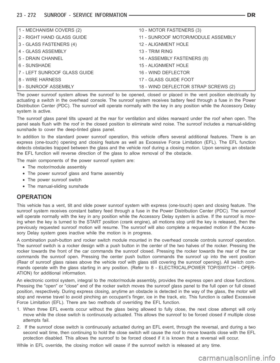
1 - MECHANISM COVERS (2) 10 - MOTOR FASTENERS (3)
2 - RIGHT HAND GLASS GUIDE 11 - SUNROOF MOTOR/MODULE ASSEMBLY
3 - GLASS FASTENERS (4) 12 - ALIGNMENT HOLE
4 - GLASS ASSEMBLY 13 - TRIM RING
5 - DRAIN CHANNEL 14 - ASSEMBLY FASTENERS (8)
6 - SUNSHADE 15 - ALIGNMENT HOLE
7 - LEFT SUNROOF GLASS GUIDE 16 - WIND DEFLECTOR
8 - WIRE HARNESS 17 - GLASS GUIDE FOOT
9 - SUNROOF ASSEMBLY 18 - WIND DEFLECTOR STRAP SCREWS (2)
The power sunroof system allows the sunroof to be opened, closed or placed in the vent position electrically by
actuating a switch in the overhead console. The sunroof system receives battery feed through a fuse in the Power
Distribution Center (PDC). The sunroof will operate normally with the keyin any position while the Accessory Delay
system is active.
The sunroof glass panel tilts upward at the rear for ventilation and slidesrearward under the roof when open. The
panel seals flush with the roof in the closed position to eliminate wind noise. The sunroof includes a manual-sliding
sunshade to cover the deep-tinted glass panel.
In addition to the standard power sunroof operation, this vehicle offers several additional features. There is an
express (one-touch) opening and closing feature as well as Excessive Force Limitation (EFL). The EFL function
detects obstacles trapped between the glass and the vehicle roof during a closing motion. Upon sensing an obstacle
the EFL function will reverse direction of the glass to allow removal of theobstacle.
The main components of thepower sunroof system are:
The motor/module assembly
The power sunroof glass and frame assembly
The power sunroof switch
The manual-sliding sunshade
OPERATION
This vehicle has a vent, tilt and slide power sunroof system with express (one-touch) open and closing feature. The
sunroof system receives constant battery feed through a fuse in the Power Distribution Center (PDC). The sunroof
will operate normally with the key in any position while the Accessory Delay system is active. If the sunroof is mov-
ing when the key is turned to the START position (crank engine), all motionsstop until the key is released, then the
previously requested sunroof motion will resume. The sunroof will also complete a requested motion if the Acces-
sory Delay system goes inactivewhile the motion is in progress.
A combination push-button and rocker switch module mounted in the overhead console controls sunroof operation.
The sunroof switch is a rocker design with a push button in the center of the two halves of the rocker. Pressing the
rocker towards the front of the car commands the sunroof closed. Pressing the rocker towards the rear of the car
commands the sunroof open. Pressing the center push button commands the sunroof up into the vent position
(Rear of sunroof glass raises above the vehicle roof with glass still covering the sunroof opening). All switch com-
mands operate with the glass startingin any position. (Refer to 8 - ELECTRICAL/POWER TOP/SWITCH - OPER-
ATION) for additional information.
An electronic control system, integralto the motor/module assembly, provides the express open and close functions.
Pressing the
openorcloseend of the rocker switch moves the sunroof glass panel to the full open or fullclosed
position, respectively. During express closing, anytime an obstacle is detected in the way of the glass, the motor will
stop and reverse travel to avoid pinching an occupant’s finger, ice in the track, etc. This function is called Excessive
Force Limitation (EFL). There are two methods of overriding the EFL function.
1. When three EFL events occur without the glass being allowed to fully close, the next close attempt will only
move while the close switch is continuously actuated. This allows the sunrooftobeforcedclosedifmultipleclose
attempts fail.
2. If the sunroof close switch is continuously actuated during an EFL event, through the reversal, and during a two
second wait time, then continuing to hold the close switch will cause the roof to move towards close with the EFL
protection disabled. This allows the sunroof to be forced closed if it is known that a reversal will occur.
While in EFL override, the closing motion will cease if the sunroof switch is released at any time.