2006 DODGE RAM SRT-10 key battery
[x] Cancel search: key batteryPage 1485 of 5267
NOTE: If this vehicle is equipped with an Electronic Throttle Control system, and the APP Sensors, PCM, or
Throttle Body Assembly have been replaced, use the scan tool to perform theETC RELEARN function.
14. If the indicator ball shows a leak present, perform the smoke test indicated in the previous test and identify the
leak and repair. Perform this verification test when the repair is complete.
Didtheindicatorballindicatethealeakispresent?
Ye s>>
Repeat the DTC test to identify the leak and repair.
No>>
Repair is complete.
5.POWERTRAIN VERIFICATION TEST 4
NOTE: 1. After completing the Powertrain Verification Test the Transmission Verification Test must be per-
formed.
NOTE: 2. If the PCM has been replaced and the correct VIN and mileage have notbeen programmed, a DTC
will set in the ABS Module, Airbag Module and the SKIM/SKREEM.
NOTE: 3. If the vehicle is equipped with a Sentry Key Remote Entry, Secret Key data must be updated. Refer
to the Service Information for the PCM, SKIM/SKREEM and the Transponder (ignition key) for programming
information. Using the scan tool, program the Secret Key information intothe PCM using the PCM replaced
function under the WCM menu.
NOTE: 4. If this vehicle is equipped with an Electronic Throttle Control system, and the APP Sensors, PCM,
or Throttle Body Assembly have been replaced, use the scan tool to perform the ETC RELEARN function.
NOTE: 5. When replacing an O2 Sensor, the PCM RAM memory must be cleared, either by disconnecting the
PCM C1 connector or momentarily disconnecting the Battery negative terminal.
6. The NGC learns the characteristics of each O2 heater element and these old values should be cleared when
installing a new O2 sensor. The customermay experience driveability issues if this is not performed.
7. Inspect the vehicle to make sure that all engine components are properlyinstalled and connected. Reassemble
and reconnect components as necessary.
8. Connect the scan tool to the data link connector.
9. Make sure the fuel tank has at least a quarter tank of fuel. Turn off all accessories.
10. If the Catalyst was replaced, with the scan tool go to the MiscellaneousMenu Option
Catalyst Replacedand
press enter.
11. If a Comprehensive Component DTC was repaired, perform steps 12 - 14. Ifa Major OBDII Monitor DTC was
repaired skip those steps and continue verification.
12. After the ignition has been off for at least 10 seconds, restart the vehicle and run 2 minutes.
13. With the scan tool, monitor the appropriate pre-test enabling conditions until all conditions have been met. Once
the conditions have been met, switch screen to the appropriate OBDII monitor, (Audible beeps when the monitor is
running).
14. If the repaired OBDII trouble code has reset or was seen in the monitor while on the road test, the repair is not
complete. Check for any related technical service bulletins or flash updates and return to Engine Electrical Diag-
nostic List.
15. If the conditions cannot be duplicated, erase all DTCs with the Scan tool.
16. If another DTC has set, return to the Engine Electrical Diagnostic Listand follow the path specified for that DTC.
Did the OBDII Monitor run successfully and has the Good Trip Counter changed to one or more?
Ye s>>
Repair is complete.
No>>
Check for any related Technical Service Bulletins and/or refer to the appropriate Diagnostic Procedure.
Page 1578 of 5267
INSTALLATION
CAUTION: To prevent severe damage to the Crank-
shaft, Damper or Special Tool 8512–A, thoroughly
clean the damper bore and the crankshaft nose
before installing Damper.
1. Align crankshaft damper slot with key in crankshaft.
Slide damper onto crankshaft slightly.
CAUTION: Special Tool 8512–A, is assembled in a
specific sequence. Failure to assemble this tool in
this sequence can result in tool failure and severe
damage to either the tool or the crankshaft.
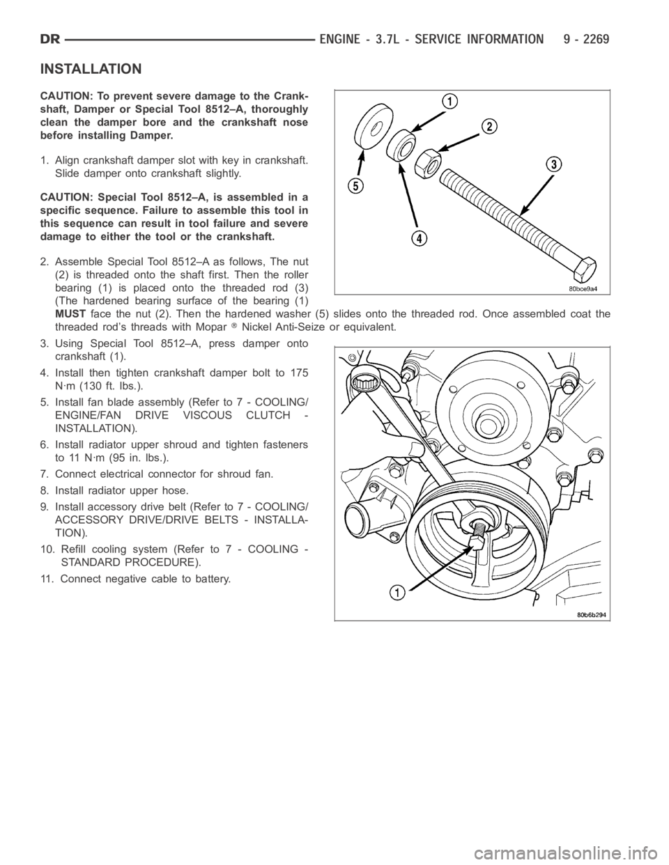
2. Assemble Special Tool 8512–A as follows, The nut
(2) is threaded onto the shaft first. Then the roller
bearing (1) is placed onto the threaded rod (3)
(The hardened bearing surface of the bearing (1)
MUSTface the nut (2). Then the hardened washer (5) slides onto the threaded rod.Once assembled coat the
threaded rod’s threads with Mopar
Nickel Anti-Seize or equivalent.
3. Using Special Tool 8512–A, press damper onto
crankshaft (1).
4. Install then tighten crankshaft damper bolt to 175
Nꞏm (130 ft. lbs.).
5. Install fan blade assembly (Refer to 7 - COOLING/
ENGINE/FAN DRIVE VISCOUS CLUTCH -
INSTALLATION).
6. Install radiator upper shroud and tighten fasteners
to 11 Nꞏm (95 in. lbs.).
7. Connect electrical connector for shroud fan.
8. Install radiator upper hose.
9. Install accessory drive belt (Refer to 7 - COOLING/
ACCESSORY DRIVE/DRIVE BELTS - INSTALLA-
TION).
10. Refill cooling system (Refer to 7 - COOLING -
STANDARD PROCEDURE).
11. Connect negative cable to battery.
Page 1713 of 5267
INSTALLATION
CAUTION: To prevent severe damage to the Crank-
shaft, Damper or Special Tool 8512–A, thoroughly
clean the damper bore and the crankshaft nose
before installing Damper.
1. Align crankshaft damper slot with key in crankshaft.
Slide damper onto crankshaft slightly.
CAUTION: Special Tool 8512–A, is assembled in a
specific sequence. Failure to assemble this tool in
this sequence can result in tool failure and severe
damage to either the tool or the crankshaft.
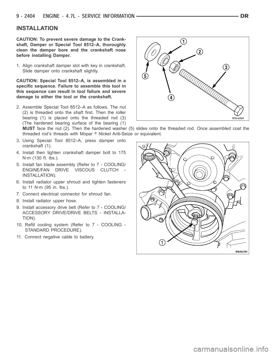
2. Assemble Special Tool 8512–A as follows, The nut
(2) is threaded onto the shaft first. Then the roller
bearing (1) is placed onto the threaded rod (3)
(The hardened bearing surface of the bearing (1)
MUSTface the nut (2). Then the hardened washer (5) slides onto the threaded rod.Once assembled coat the
threaded rod’s threads with Mopar
Nickel Anti-Seize or equivalent.
3. Using Special Tool 8512–A, press damper onto
crankshaft (1).
4. Install then tighten crankshaft damper bolt to 175
Nꞏm (130 ft. lbs.).
5. Install fan blade assembly (Refer to 7 - COOLING/
ENGINE/FAN DRIVE VISCOUS CLUTCH -
INSTALLATION).
6. Install radiator upper shroud and tighten fasteners
to 11 Nꞏm (95 in. lbs.).
7. Connect electrical connector for shroud fan.
8. Install radiator upper hose.
9. Install accessory drive belt (Refer to 7 - COOLING/
ACCESSORY DRIVE/DRIVE BELTS - INSTALLA-
TION).
10. Refill cooling system (Refer to 7 - COOLING -
STANDARD PROCEDURE).
11. Connect negative cable to battery.
Page 1896 of 5267
TIMING CHAIN & SPROCKETS
REMOVAL
1. Disconnect battery negative cable.
2. Drain cooling system.
3. Remove Timing Chain Cover (1).
4. Re-install the vibration damper bolt finger tight.
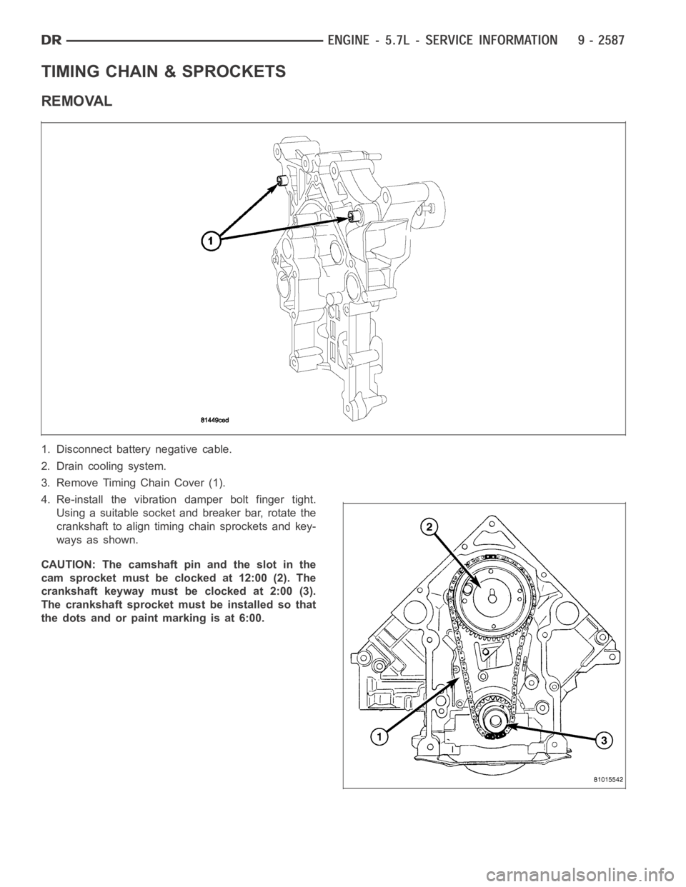
Using a suitable socket and breaker bar, rotate the
crankshaft to align timing chain sprockets and key-
ways as shown.
CAUTION: The camshaft pin and the slot in the
cam sprocket must be clocked at 12:00 (2). The
crankshaft keyway must be clocked at 2:00 (3).
The crankshaft sprocket must be installed so that
the dots and or paint marking is at 6:00.
Page 2298 of 5267
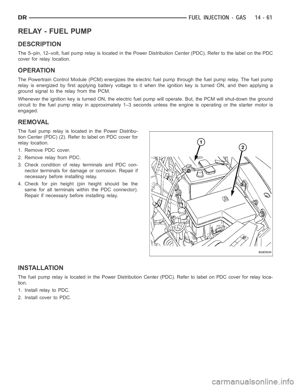
RELAY - FUEL PUMP
DESCRIPTION
The 5–pin, 12–volt, fuel pump relay is located in the Power Distribution Center (PDC). Refer to the label on the PDC
cover for relay location.
OPERATION
The Powertrain Control Module (PCM) energizes the electric fuel pump through the fuel pump relay. The fuel pump
relay is energized by first applying battery voltage to it when the ignition key is turned ON, and then applying a
ground signal to the relay from the PCM.
Whenever the ignition key is turned ON, the electric fuel pump will operate. But, the PCM will shut-down the ground
circuit to the fuel pump relay in approximately 1–3 seconds unless the engine is operating or the starter motor is
engaged.
REMOVAL
The fuel pump relay is located in the Power Distribu-
tion Center (PDC) (2). Refer to label on PDC cover for
relay location.
1. Remove PDC cover.
2. Remove relay from PDC.
3. Check condition of relay terminals and PDC con-
nector terminals for damage or corrosion. Repair if
necessary before installing relay.
4. Check for pin height (pin height should be the
same for all terminals within the PDC connector).
Repair if necessary before installing relay.
INSTALLATION
The fuel pump relay is located in the Power Distribution Center (PDC). Refer to label on PDC cover for relay loca-
tion.
1. Install relay to PDC.
2. Install cover to PDC.
Page 2413 of 5267
COLUMN
DESCRIPTION
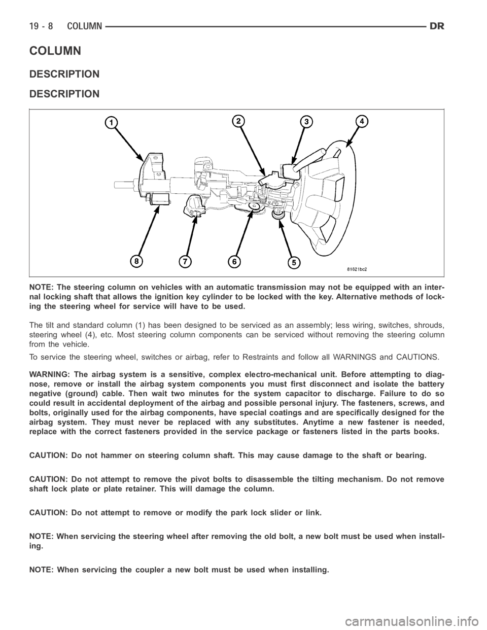
DESCRIPTION
NOTE: The steering column on vehicles with an automatic transmission may not be equipped with an inter-
nal locking shaft that allows the ignition key cylinder to be locked with the key. Alternative methods of lock-
ing the steering wheel for service will have to be used.
The tilt and standard column (1) has been designed to be serviced as an assembly; less wiring, switches, shrouds,
steering wheel (4), etc. Most steering column components can be serviced without removing the steering column
from the vehicle.
To service the steering wheel, switches or airbag, refer to Restraints andfollow all WARNINGS and CAUTIONS.
WARNING: The airbag system is a sensitive, complex electro-mechanical unit. Before attempting to diag-
nose, remove or install the airbag system components you must first disconnect and isolate the battery
negative (ground) cable. Then wait two minutes for the system capacitor todischarge. Failure to do so
could result in accidental deployment of the airbag and possible personalinjury. The fasteners, screws, and
bolts, originally used for the airbag components, have special coatings and are specifically designed for the
airbag system. They must never be replaced with any substitutes. Anytime anew fastener is needed,
replace with the correct fasteners provided in the service package or fasteners listed in the parts books.
CAUTION: Do not hammer on steering column shaft. This may cause damage to the shaft or bearing.
CAUTION: Do not attempt to remove the pivot bolts to disassemble the tilting mechanism. Do not remove
shaft lock plate or plate retainer. This will damage the column.
CAUTION: Do not attempt to remove or modify the park lock slider or link.
NOTE: When servicing the steering wheel after removing the old bolt, a new bolt must be used when install-
ing.
NOTE: When servicing the coupler a new bolt must be used when installing.
Page 2414 of 5267
DESCRIPTION - SRT10
The SRT-10 column has noSTARTposition on the key cylinder. The push starter button switch is mounted on the
Instrument panel center stack. All SRT-10 columns are Tilt columns, Standard cab trucks come with manual trans-
missions, Quad cab trucks come equipped with automatic transmissions.
DIAGNOSIS AND TESTING
STEERING COLUMN
If the vehicle is involved in a front end collision/the air bag has deployedthe column must be inspected. This
inspection will determine if the Column has collapsed. Inspect the columnmounting capsules visually and manually
push and pull them to check for separation or fractures. If capsules are fractured or have moved the column MUST
be replaced.
REMOVAL
WARNING: Before servicing the steering column the airbag system must be disarmed. Refer to electrical
restraint system for service procedures. Failure to do so may result in accidental deployment of the airbag
and possible personal injury.
CAUTION: All fasteners must be torqued to specification to ensure proper operation of the steering column.
1. Position the front wheelsstraight ahead.
2. Disconnect the negative (ground) cable from the battery.
3. Remove the airbag, (Refer to 8 - ELECTRICAL/RE-
STRAINTS/DRIVER AIRBAG - REMOVAL).
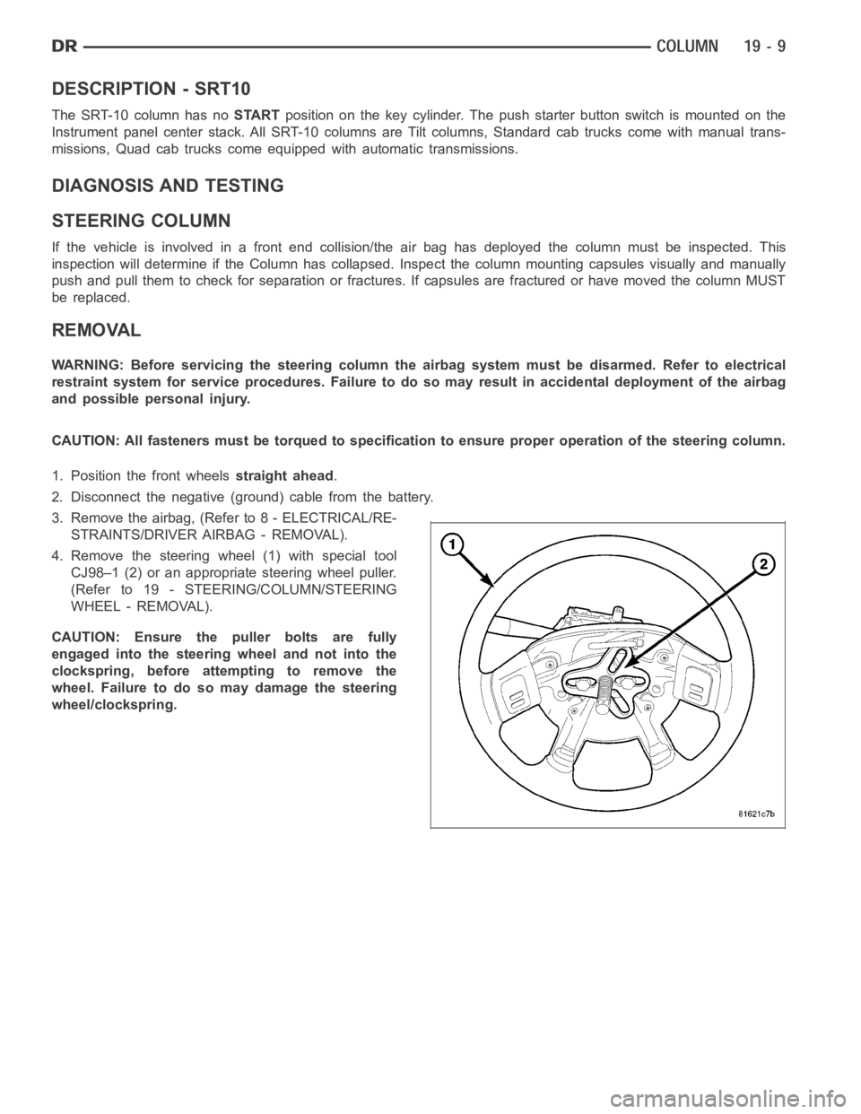
4. Remove the steering wheel (1) with special tool
CJ98–1 (2) or an appropriate steering wheel puller.
(Refer to 19 - STEERING/COLUMN/STEERING
WHEEL - REMOVAL).
CAUTION: Ensure the puller bolts are fully
engaged into the steering wheel and not into the
clockspring, before attempting to remove the
wheel. Failure to do so may damage the steering
wheel/clockspring.
Page 2421 of 5267
REMOVAL
SERVICE PRECAUTIONS
NOTE: The steering column on vehicles equipped with an automatic transmission is not equipped with an
internal locking shaft with the ignition cylinder. Alternative methods of locking the steering wheel for ser-
vice will have to be used.
To service the steering wheel, switches or airbag, Refer to Electrical Restraints and follow all WARNINGS and CAU-
TIONS.
WARNING: The airbag system is a sensitive, complex electro-mechanical unit. Before attempting to diag-
nose, remove or install the airbag system components you must first disconnect and isolate the battery
negative (ground) cable. Then wait two minutes for the system capacitor todischarge. Failure to do so
could result in accidental deployment of the airbag and possible personalinjury. The fasteners, screws, and
bolts, originally used for the airbag components, have special coatings and are specifically designed for the
airbag system. They must never be replaced with any substitutes. Anytime anew fastener is needed,
replace with the correct fasteners provided in the service package or fasteners listed in the parts books.
CAUTION: Do not hammer on steering column shaft. This may cause damage to the shaft or bearing.
CAUTION: Do not attempt to remove the pivot bolts to disassemble the tilting mechanism.
The ignition key must be in the key cylinder for cylinder removal. The key cylinder must be removed first before
removing ignition switch.
1. Remove the negative (ground) cable from the battery.
2. Disable the airbag, (Refer to 8 - ELECTRICAL/RESTRAINTS/DRIVER AIRBAG- REMOVAL).
3. Remove the kneeblocker and steering column reinforcement panel.
4. Remove the lower and upper shrouds.
5. Remove key cylinder. (Refer to 19 - STEERING/COLUMN/LOCK CYLINDER HOUSING - REMOVAL).
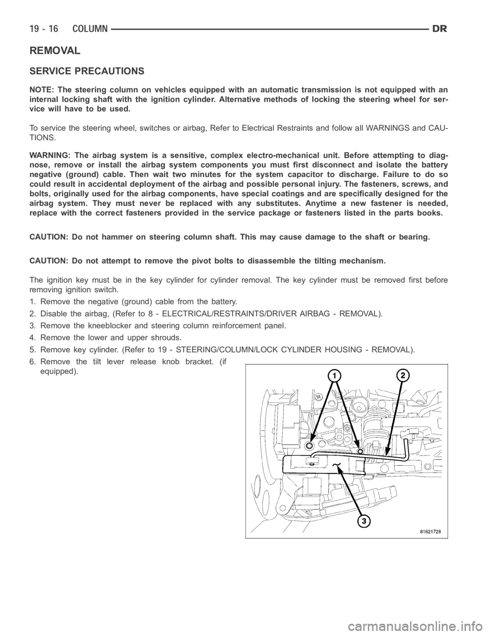
6. Remove the tilt lever release knob bracket. (if
equipped).