2006 DODGE RAM SRT-10 air condition
[x] Cancel search: air conditionPage 2895 of 5267
P1790-FAULT IMMEDIATELY AFTER SHIFT
For a complete wiring diagramRefer to Section 8W.
When Monitored:
After a Gear Ratio Error code is stored.
Set Condition:
After a Gear Ratio Error DTC has already been set. The DTC is set if the fault happened within 1.3 seconds
of a shift. The DTC set time will vary from 1.214 seconds to 15 seconds.
Possible Causes
FAULT AFTER SHIFT
Always perform the 42RLE Pre-Diagnostic Troubleshooting procedure before proceeding. (Refer to 21 -
TRANSMISSION/TRANSAXLE/AUTOMATIC - 42RLE - STANDARD PROCEDURE)
Theory of Operation
This DTC is not stored alone. It is stored if a Gear Ratio DTC is detected immediately after shift. The existence of
DTC P1790 indicates a mechanical or hydraulic (not electrical) related problems. It should be noted, however, that
all mechanical problems don’t necessarily result in DTC P1790. When this DTC exists, diagnosing the system
should be based on the associated DTC and only mechanical causes should be considered.
Diagnostic Test
1.FAULT AFTER SHIFT
This DTC is set along with a Gear Ratio DTC. Perform the appropriate test forthe Gear Ratio DTC stored.
NOTE: Check Pending DTCs or 1 trip failures if there are no Active or Stored Gear Ratio DTCs.
If there are no possible causes remaining, view repair.
Repair
Refer to the Transmission category and perform the appropriate symptom.
Perform 42RLE TRANSMISSION VERIFICATION TEST - VER 1. (Refer to 21 - TRANSMISSION/
TRANSAXLE/AUTOMATIC - 42RLE - STANDARD PROCEDURE)
Page 2898 of 5267

2.(T13) SPEED SENSOR GROUND CIRCUIT OPEN
Turn the ignition off to the lock position.
Disconnect the PCM C4 harness connector.
Disconnect the Input and Output Speed Sensor harness connectors.
CAUTION: Do not probe the PCM harness connectors. Probing the
PCM harness connectors will damage the PCM terminals resulting
in poor terminal to pin connection. Install Miller tool #8815 to per-
form diagnosis.
Measure the resistance of both of the (T13) Speed Sensor Ground cir-
cuits from the appropriate terminal of special tool #8815 to the Input
and Output Speed Sensor harness connectors.
Is the resistance above 5.0 ohms on either circuit?
Ye s>>
Repair the (T13) Speed Sensor Ground circuit for an open.
Perform 42RLE TRANSMISSION VERIFICATION TEST -
VER 1. (Refer to 21 - TRANSMISSION/TRANSAXLE/AU-
TOMATIC - 42RLE - STANDARD PROCEDURE)
No>>
Using the schematics as a guide, check the Powertrain
Control Module (PCM) terminals for corrosion, damage, or
terminal push out. Pay particular attention to all power and
ground circuits. If no problems are found, replace the PCM
per the Service Information.With the scan tool, perform
QUICK LEARN
Perform 42RLE TRANSMISSION VERIFICATION TEST - VER 1. (Refer to 21 - TRANSMISSION/
TRANSAXLE/AUTOMATIC - 42RLE - STANDARD PROCEDURE)
3.INTERMITTENT WIRING AND CONNECTORS
The conditions necessary to set the DTC are not present at this time.
Using the schematics as a guide, inspect the wiring and connectors specifictothiscircuit.
Wiggle the wires while checking for shorted and open circuits.
With the scan tool, check the DTC EVENT DATA to help identify the conditionsin which the DTC was set.
Were there any problems found?
Ye s>>
Repair as necessary.
Perform 42RLE TRANSMISSION VERIFICATION TEST - VER 1. (Refer to 21 - TRANSMISSION/
TRANSAXLE/AUTOMATIC - 42RLE - STANDARD PROCEDURE)
No>>
Te s t C o m p l e t e .
Page 2899 of 5267
P1797-MANUAL SHIFT OVERHEAT
For a complete wiring diagramRefer to Section 8W.
When Monitored:
Continuously with engine running.
Set Condition:
If the Engine Temperature exceeds 123° C (255° F) or the Transmission Temperature exceeds 135° C (275° F)
while in AutoStick
mode. Note: Aggressive driving or driving in low for extended periods of time will set this
DTC.
Possible Causes
MANUAL SHIFT OVERHEAT
Always perform the 42RLE Pre-Diagnostic Troubleshooting procedure before proceeding. (Refer to 21 -
TRANSMISSION/TRANSAXLE/AUTOMATIC - 42RLE - STANDARD PROCEDURE)
Theory of Operation
The major cause of heat build up in the transmission is torque converter slip.WiththetransmissionintheAuto-
Stick
mode, the torque converter can slip during aggressive driving or heavy loading conditions such as trailer
towing or driving up steep grades. In the non AutoStick
mode, internal controller logic prevents the transmission
from overheating by managing the shift and EMCC schedule. In the AutoStick
mode, when the transmission or
engine temperature approaches an overheat condition, the manual shift overheat DTC sets and the AutoStick
mode is temporarily suspended until the temperature returns to normal.
Diagnostic Test
1.MANUAL SHIFT OVERHEAT
This is an informational DTC only.
With the scan tool, check the DTC EVENT DATA to help identify the conditionsin which the DTC was set.
Check the engine and transmission cooling system for proper operation.
Check the Radiator Cooling Fan operation.
Check the Transmission Cooling operation.
Check the Transmission Fluid Level per the Service Information to verify that it is not overfilled.
NOTE: Aggressive driving or driving in low for extended periods of time will set this DTC.
If there are no possible causes remaining, view repair.
Repair
If the Transmission Fluid is low, repair any Transmission Fluid leak as necessary and adjust the Trans-
mission Fluid Level per the Service Information. Refer to Service Information for the related symptoms
and repair as necessary.
Perform 42RLE TRANSMISSION VERIFICATION TEST - VER 1. (Refer to 21 - TRANSMISSION/
TRANSAXLE/AUTOMATIC - 42RLE - STANDARD PROCEDURE)
Page 2908 of 5267
STANDARD PROCEDURE
PRE-DIAGNOSTIC TROUBLESHOOTING PROCEDURE - 42RLE
For a complete wiring diagramRefer to Section 8W.
1.
Perform the following steps prior to any diagnostic procedure:
Many transmission symptoms can be caused by a low fluid level. If the fluid level is low, locate and repair any
leaks and fill the transmission to the proper fluid level. Refer to the Service Information for the proper repair
and fluid fill procedures.
Testing should only be performed with the battery fully charged to avoid false diagnosis.
With the scan tool, read Engine (PCM) DTCs. If Engine DTCs are present, refer to the Driveability Category
and perform to the appropriate diagnostic procedure(s) before proceeding.
With the scan tool, read Transmission (TCM) DTCs. Record all Stored, Active, and Pending DTC information.
Diagnose any Pending DTC as a matured DTC.
With the scan tool, read DTC EVENT DATA.Use this data to identify the conditions in which the DTC was set.
Note: Performing a Battery Disconnect will clear all DTC EVENT DATA and reset all learned Transmis-
sion values to the controllers default values, which may temporarily result in erratic shift schedules.
With the scan tool, perform the Shift Lever Position Test. If the test does not pass, refer to the diagnostic
procedure for P0706-Check Shifter Signal.
For Gear Ratio Error DTCs, use the scan tool to read and record the Clutch Volume Index (CVI) information.
Use the wiring diagram as a guide, inspect the wiring and connectors related to this circuit and repair as nec-
essary.
Refer to the When Monitored and Set Conditions for this DTC. DTCs can set at ignition on, at start up, driving
under specific conditions, and after controller diagnostic monitors haverun.
Refer to applicable Technical Service Bulletins (TSBs) for controller software update information. Some condi-
tions can be corrected by upgrading the Engine (PCM) or Transmission (TCM)controller software.
Check for any Service Information Tune-ups or Service Bulletins for any possible causes that may apply.
Were there any repairs made that fixed the vehicle?
Ye s>>
Testing complete.
Perform 42RLE VERIFICATION TEST - VER1(Referto21-TRANSMISSION/TRANSAXLE/AUTO-
MATIC - 42RLE - STANDARD PROCEDURE)
No>>
Refer to the Transmission category and perform the appropriate diagnostic procedure(s). (Refer to 21 -
TRANSMISSION/TRANSAXLE/AUTOMATIC - 42RLE - DIAGNOSIS AND TESTING)
Page 2909 of 5267
42RLE TRANSMISSION VERIFICATION TEST - VER 1
1.
Perform the following after completion of a diagnostic repair:
Note: After completion of the Transmission Verification Test, the Powertrain Verification Test must be
performed. Refer to the Engine Category.
Reconnect any disconnected components.
With the scan tool, erase all Transmission and Engine DTCs.
Erase DTC P0700 under engine to turn off the MIL off after completion of transmission repairs.
Perform *PRNDL FAULT CLEARING PROCEDURE after completion of repairs for P0706-TRANSMISSION
RANGE SENSOR RATIONALITY.
If the Powertrain Control Module or the Transmission has been repaired or replaced, it is necessary to perform
the scan tool Quick Learn Procedure.
If the Torque converter has been replaced, with the scan tool perform TCC BREAK-IN.
If the Powertrain Control Module or Front Control Module has been replacedyoumustresetthePinionFactor
in the Front Control Module.
With the scan tool, display Transmission Temperature. Start and run the engine until the Transmission Tem-
perature is HOT, above 43° C or 110° F.
Check the transmission fluid and adjust if necessary. Refer to the ServiceInformation for the Fluid Fill proce-
dure.
Road test the vehicle. With the scan tool, monitor the engine RPM. Make 15 to20 1-2, 2-3, 3-4 upshifts.
Perform these shifts from a standing start to 45 mph with a constant throttleopeningof20to25degrees.
With speeds below 25 MPH, make 5 to 8 wide open throttle kickdowns to 1st gear. Allow at least 5 seconds
each in 2nd and 3rd gear between each kickdown.
For a specific DTC, drive the vehicle to the Symptom’s When Monitored/WhenSet conditions to verify the DTC
is repaired.
If equipped with AutoStick, upshift and downshift several times using the AutoStickfeature during the road
test.
Note: Use the OBDII task manager to run a Good Trip in each gear, this will confirm the repair and to
ensure that the DTC has not re-matured.
Check for any Diagnostic Trouble Codes (DTCs) during and after the road test.
Did any Diagnostic Trouble Codes set during the road test?
Ye s>>
Repair is not complete. Refer to the Transmission category and perform theappropriate symptom(s).
(Refer to 21 - TRANSMISSION/TRANSAXLE/AUTOMATIC - 42RLE - DIAGNOSIS AND TESTING)
No>>
Repair is complete.
Page 2914 of 5267
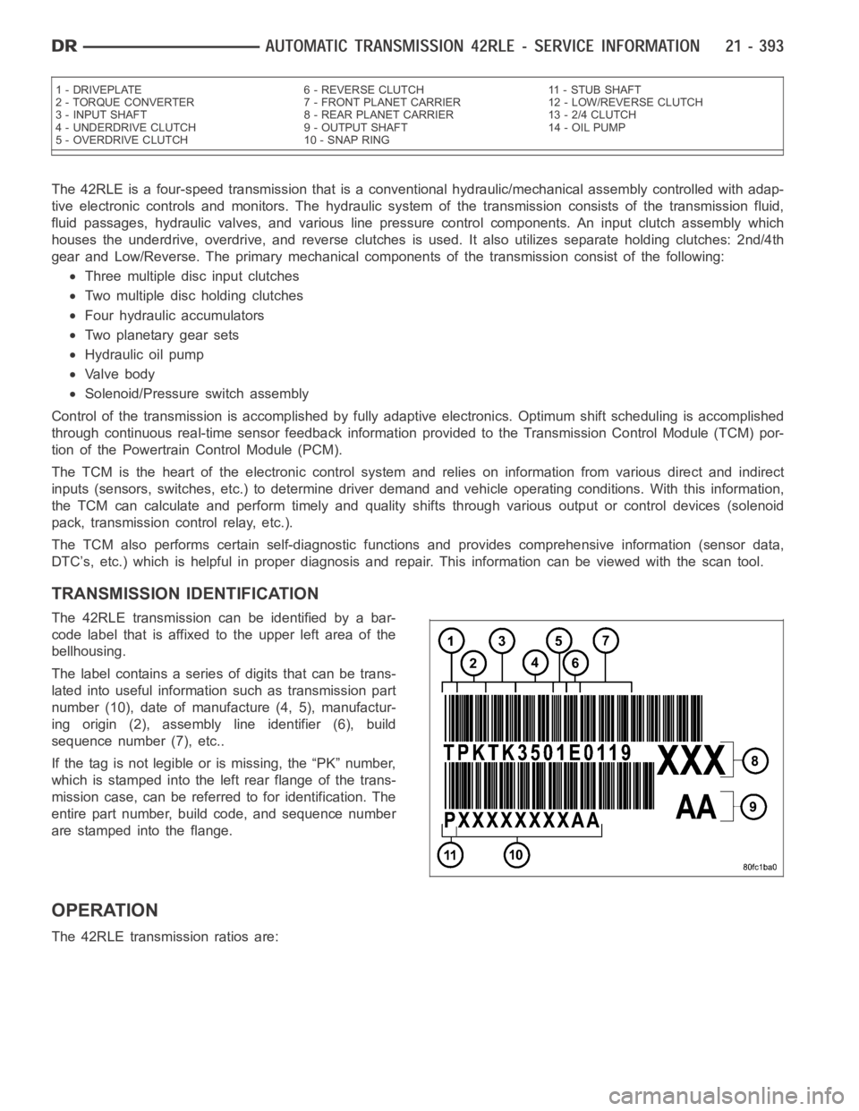
The 42RLE is a four-speed transmission that is a conventional hydraulic/mechanical assembly controlled with adap-
tive electronic controls and monitors. The hydraulic system of the transmission consists of the transmission fluid,
fluid passages, hydraulic valves, and various line pressure control components. An input clutch assembly which
houses the underdrive, overdrive, and reverse clutches is used. It also utilizes separate holding clutches: 2nd/4th
gear and Low/Reverse. The primary mechanical components of the transmission consist of the following:
Three multiple disc input clutches
Two multiple disc holding clutches
Four hydraulic accumulators
Two planetary gear sets
Hydraulic oil pump
Valve body
Solenoid/Pressure switch assembly
Control of the transmission is accomplished by fully adaptive electronics. Optimum shift scheduling is accomplished
through continuous real-time sensor feedback information provided to the Transmission Control Module (TCM) por-
tion of the Powertrain Control Module (PCM).
The TCM is the heart of the electronic control system and relies on information from various direct and indirect
inputs (sensors, switches, etc.) to determine driver demand and vehicle operating conditions. With this information,
the TCM can calculate and perform timely and quality shifts through various output or control devices (solenoid
pack, transmission control relay, etc.).
The TCM also performs certain self-diagnostic functions and provides comprehensive information (sensor data,
DTC’s, etc.) which is helpful in proper diagnosis and repair. This informationcanbeviewedwiththescantool.
TRANSMISSION IDENTIFICATION
The 42RLE transmission can be identified by a bar-
code label that is affixed to the upper left area of the
bellhousing.
The label contains a series of digits that can be trans-
lated into useful information such as transmission part
number (10), date of manufacture (4, 5), manufactur-
ing origin (2), assembly line identifier (6), build
sequence number (7), etc..
If the tag is not legible or is missing, the “PK” number,
which is stamped into the left rear flange of the trans-
mission case, can be referred to for identification. The
entire part number, build code, and sequence number
are stamped into the flange.
OPERATION
The 42RLE transmission ratios are:
1 - DRIVEPLATE 6 - REVERSE CLUTCH 11 - STUB SHAFT
2 - TORQUE CONVERTER 7 - FRONT PLANET CARRIER 12 - LOW/REVERSE CLUTCH
3 - INPUT SHAFT 8 - REAR PLANET CARRIER 13 - 2/4 CLUTCH
4 - UNDERDRIVE CLUTCH 9 - OUTPUT SHAFT 14 - OIL PUMP
5 - OVERDRIVE CLUTCH 10 - SNAP RING
Page 2919 of 5267
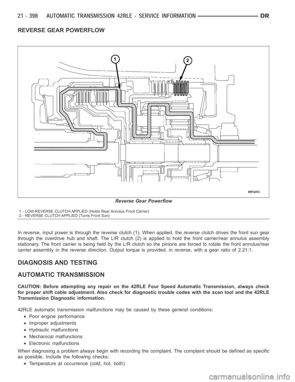
REVERSE GEAR POWERFLOW
In reverse, input power is through the reverse clutch (1). When applied, the reverse clutch drives the front sun gear
through the overdrive hub and shaft. The L/R clutch (2) is applied to hold the front carrier/rear annulus assembly
stationary. The front carrier is being held by the L/R clutch so the pinionsare forced to rotate the front annulus/rear
carrier assembly in the reverse direction. Output torque is provided, in reverse, with a gear ratio of 2.21:1.
DIAGNOSIS AND TESTING
AUTOMATIC TRANSMISSION
CAUTION: Before attempting any repair on the 42RLE Four Speed Automatic Transmission, always check
for proper shift cable adjustment. Also check for diagnostic trouble codes with the scan tool and the 42RLE
Transmission Diagnostic information.
42RLE automatic transmission malfunctions may be caused by these generalconditions:
Poor engine performance
Improper adjustments
Hydraulic malfunctions
Mechanical malfunctions
Electronic malfunctions
When diagnosing a problem always begin with recording the complaint. The complaint should be defined as specific
as possible. Includethe following checks:
Temperature at occurrence (cold, hot, both)
Reverse Gear Powerflow
1 - LOW-REVERSE CLUTCH APPLIED (Holds Rear Annulus Front Carrier)
2 - REVERSE CLUTCH APPLIED (Turns Front Sun)
Page 3014 of 5267
FLUID AND FILTER
DIAGNOSIS AND TESTING
CAUSES OF BURNT FLUID
Burnt, discolored fluid is a result of overheating which has two primary causes.
1. A result of restricted fluid flow through the main and/or auxiliary cooler. This condition is usually the result of a
faulty or improperly installed drainback valve, a damaged oil cooler, or severe restrictions in the coolers and lines
caused by debris or kinked lines.
2. Heavy duty operation with a vehicle not properly equipped for this type of operation. Trailer towing or similar high
load operation will overheat the transmission fluid if the vehicle is improperly equipped. Such vehicles should
have an auxiliary transmission fluid cooler, a heavy duty cooling system,and the engine/axle ratio combination
needed to handle heavy loads.
EFFECTS OF INCORRECT FLUID LEVEL
Alowfluidlevelallowsthepumptotakeinairalongwiththefluid.Airinthe fluid will cause fluid pressures to be
low and develop slower than normal. If the transmission is overfilled, thegears churn the fluid into foam. This aer-
ates the fluid and causing the same conditions occurring with a low level. In either case, air bubbles cause fluid
overheating, oxidation, and varnish buildup which interferes with valveand clutch operation. Foaming also causes
fluid expansion which can result in fluid overflow from the transmission vent or fill tube. Fluid overflow can easily be
mistaken for a leak if inspection is not careful.
FLUID CONTAMINATION
Transmission fluid contamination is generally a result of:
adding incorrect fluid
failure to clean dipstick and fill tube when checking level
engine coolant entering the fluid
internal failure that generates debris
overheat that generates sludge (fluid breakdown)
failure to replace contaminated converter after repair
The use of non-recommended fluids can result in transmission failure. Theusual results are erratic shifts, slippage,
abnormal wear and eventual failure due to fluid breakdown and sludge formation. Avoid this condition by using rec-
ommended fluids only.
The dipstick cap and fill tube should be wiped clean before checking fluid level. Dirt, grease and other foreign mate-
rial on the cap and tube could fall into the tube if not removed beforehand. Take the time to wipe the cap and tube
clean before withdrawing the dipstick.
Engine coolant in the transmission fluid is generally caused by a cooler malfunction. The only remedy is to replace
the radiator as the cooler in the radiator is not a serviceable part. If coolant has circulated through the transmission,
an overhaul is necessary.
The torque converter should also be replaced whenever a failure generatessludge and debris. This is necessary
because normal converter flushing procedures will not remove all contaminants.
STANDARD PROCEDURE
FLUID LEVEL CHECK
The transmission sump has a dipstick to check oil similar to most automatictransmissions. It is located on the left
side of the engine. Be sure to wipe all dirt from dipstick handle before removing.
The torque converter fills in both the PARK and NEUTRAL positions. Place the selector lever in PARK to be sure
that the fluid level check is accurate.The engine should be running at idle speed for at least one minute, with
the vehicle on level ground.At normal operating temperature (approximately 82° C or 180° F), the fluidlevel is
correct if it is in the HOT region (cross-hatched area) on the oil level indicator. The fluid level should be in COLD
region at 21° C (70° F) fluid temperature. Adjust fluid level as necessary.Use only Mopar
ATF+4, Automatic Trans-
mission Fluid.