Page 1499 of 5267
31. Disconnect crankshaft postion sensor.
32. Disconnect the engine block heater power cable, if equipped.
33. Disconnect the front propshaft at the front differ-
ential and secure out of way.
NOTE: It is necessary to disconnect the front
propshaft for access to the starter and left side
exhaust flange.
34. Remove the starter (4).
Page 1502 of 5267
8. Install the starter (4).
9. Connect the crankshaft position sensor.
10. Install the engine block heater power cable, if
equipped.
CAUTION: The structural cover requires a specific
torque sequence. Failure to follow this sequence
may cause severe damage to the cover.
11. Install the structural cover.
NOTE: New clamps must be used on exhaust man-
ifold flanges. Failure to use new clamps may
result in exhaust leaks.
12. Install the left and right exhaust pipes.
13. Connect the left and right oxygen sensors.
14. Lower vehicle.
15. Remove the engine lift plate.
16. Connect the knock sensors.
17. Connect the engine to body ground straps at the
left side of the cowl.
18. Install the intake manifold.
19. Install the engine oil dipstick tube.
20. Install the power brake booster vacuum hose.
21. Install the breather hoses.
22. Install the PCV hose.
23. Install the fuel rail.
24. Install the coil over plugs.
Page 1503 of 5267
25. Connect the engine wiring harness at the follow-
ing points :
Intake air temperature (IAT) sensor (4)
Fuel Injectors
Throttle Position (TPS) Switch (2)
Idle Air Control (IAC) Motor (3)
Engine Oil Pressure Switch
Engine Coolant Temperature (ECT) Sensor
Manifold Absolute Pressure MAP) Sensor
Camshaft Position (CMP) Sensor
Coil Over Plugs
Crankshaft Position Sensor
26. Reinstall the radiator/cooling module assembly.
27. Connect lower radiator hose.
28. Connect upper radiator hose.
29. Connect throttle and speed control cables.
30. Install the heater hose assembly.
31. Install coolant recovery bottle.
32. Install the power steering pump.
33. Install the generator (3).
Page 1505 of 5267

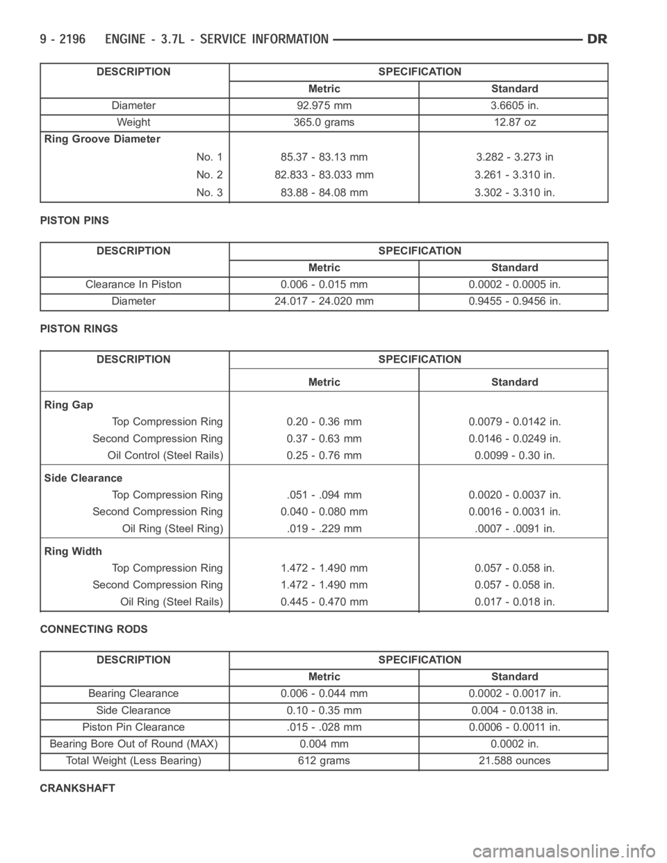
DESCRIPTION SPECIFICATION
Metric Standard
Diameter 92.975 mm 3.6605 in.
Weight 365.0 grams 12.87 oz
Ring Groove Diameter
No. 1 85.37 - 83.13 mm 3.282 - 3.273 in
No. 2 82.833 - 83.033 mm 3.261 - 3.310 in.
No. 3 83.88 - 84.08 mm 3.302 - 3.310 in.
PISTON PINS
DESCRIPTION SPECIFICATION
Metric Standard
Clearance In Piston 0.006 - 0.015 mm 0.0002 - 0.0005 in.
Diameter 24.017 - 24.020 mm 0.9455 - 0.9456 in.
PISTON RINGS
DESCRIPTION SPECIFICATION
Metric Standard
Ring Gap
Top Compression Ring 0.20 - 0.36 mm 0.0079 - 0.0142 in.
Second Compression Ring 0.37 - 0.63 mm 0.0146 - 0.0249 in.
Oil Control (Steel Rails) 0.25 - 0.76 mm 0.0099 - 0.30 in.
Side Clearance
Top Compression Ring .051 - .094 mm 0.0020 - 0.0037 in.
Second Compression Ring 0.040 - 0.080 mm 0.0016 - 0.0031 in.
Oil Ring (Steel Ring) .019 - .229 mm .0007 - .0091 in.
Ring Width
Top Compression Ring 1.472 - 1.490 mm 0.057 - 0.058 in.
Second Compression Ring 1.472 - 1.490 mm 0.057 - 0.058 in.
Oil Ring (Steel Rails) 0.445 - 0.470 mm 0.017 - 0.018 in.
CONNECTING RODS
DESCRIPTION SPECIFICATION
Metric Standard
Bearing Clearance 0.006 - 0.044 mm 0.0002 - 0.0017 in.
Side Clearance 0.10 - 0.35 mm 0.004 - 0.0138 in.
Piston Pin Clearance .015 - .028 mm 0.0006 - 0.0011 in.
Bearing Bore Out of Round (MAX) 0.004 mm 0.0002 in.
Total Weight (Less Bearing) 612 grams 21.588 ounces
CRANKSHAFT
Page 1508 of 5267

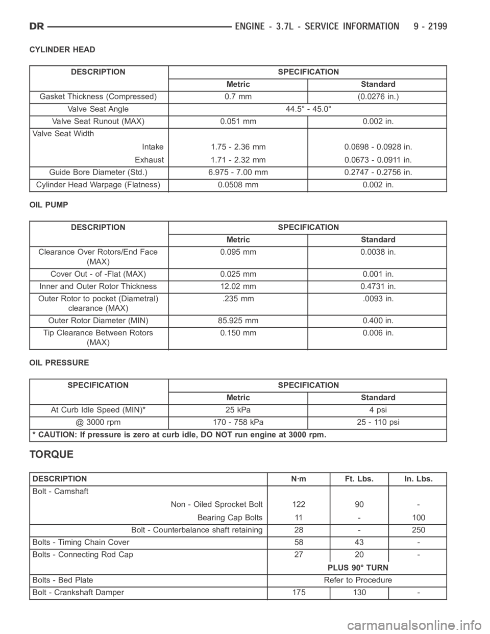
CYLINDER HEAD
DESCRIPTION SPECIFICATION
Metric Standard
Gasket Thickness (Compressed) 0.7 mm (0.0276 in.)
Valve Seat Angle 44.5° - 45.0°
Valve Seat Runout (MAX) 0.051 mm 0.002 in.
Va l v e S e a t W i d t h
Intake 1.75 - 2.36 mm 0.0698 - 0.0928 in.
Exhaust 1.71 - 2.32 mm 0.0673 - 0.0911 in.
Guide Bore Diameter (Std.) 6.975 - 7.00 mm 0.2747 - 0.2756 in.
Cylinder Head Warpage (Flatness) 0.0508 mm 0.002 in.
OIL PUMP
DESCRIPTION SPECIFICATION
Metric Standard
Clearance Over Rotors/End Face
(MAX)0.095 mm 0.0038 in.
Cover Out - of -Flat (MAX) 0.025 mm 0.001 in.
Inner and Outer Rotor Thickness 12.02 mm 0.4731 in.
Outer Rotor to pocket (Diametral)
clearance (MAX).235 mm .0093 in.
Outer Rotor Diameter (MIN) 85.925 mm 0.400 in.
Tip Clearance Between Rotors
(MAX)0.150 mm 0.006 in.
OIL PRESSURE
SPECIFICATION SPECIFICATION
Metric Standard
At Curb Idle Speed (MIN)* 25 kPa 4 psi
@ 3000 rpm 170 - 758 kPa 25 - 110 psi
* CAUTION: If pressure is zero at curb idle, DO NOT run engine at 3000 rpm.
TORQUE
DESCRIPTION Nꞏm Ft. Lbs. In. Lbs.
Bolt - Camshaft
Non - Oiled Sprocket Bolt 122 90 -
Bearing Cap Bolts 11 - 100
Bolt - Counterbalance shaft retaining 28 - 250
Bolts - Timing Chain Cover 58 43 -
Bolts - Connecting Rod Cap 27 20 -
PLUS 90° TURN
Bolts - Bed Plate Refer to Procedure
Bolt - Crankshaft Damper 175 130 -
Page 1511 of 5267
SPECIAL TOOLS
Spanner Wrench 6958
Adapter Pins 8346
Front Crankshaft Seal Remover 8511
Front Crankshaft Seal Installer 8348
Handle C-4171
Rear Crankshaft Seal Installer 8349
Rear Crankshaft Seal Remover 8506
Connecting Rod Guides 8507
Page 1512 of 5267
Crankshaft Damper Installer 8512
Puller 1026
Crankshaft Damper Removal Insert 8513
Chain Tensioner Wedge 8379
Chain Tensioner Pins 8514
VALVE SPRING COMPRESSOR 8426
ENGINE LIFTING FIXTURE 8427
CAMSHAFT HOLDER 8428
HOLDER SECONDARY CAMSHAFT CHAIN 8429
Page 1518 of 5267
7. Remove the master cylinder and booster assembly (Refer to 5 - BRAKES/HYDRAULIC/MECHANICAL/POWER
BRAKE BOOSTER - REMOVAL).
8. Remove the cylinder head cover (Refer to 9 - ENGINE/CYLINDER HEAD/CYLINDER HEAD COVER(S) -
REMOVAL).
9. Remove the fan shroud and fan blade assembly
(Refer to 7 - COOLING/ENGINE/RADIATOR FAN -
REMOVAL).
10. Remove accessory drive belt (Refer to 7 - COOL-
ING/ACCESSORY DRIVE/DRIVE BELTS -
REMOVAL).
11. Remove the power steering pump and set aside.
12. Rotate the crankshaft until the damper timing
mark is aligned with TDC indicator mark (2).
13. Verify the V6 mark on the camshaft sprocket is at the 12 o’clock position. Rotate the crankshaft one turn if
necessary.
14. Remove the crankshaft damper (Refer to 9 - ENGINE/ENGINE BLOCK/VIBRATION DAMPER - REMOVAL).
15. Remove the timing chain cover (Refer to 9 - ENGINE/VALVE TIMING/TIMINGBELT / CHAIN COVER(S) -
REMOVAL).