Page 1375 of 5267
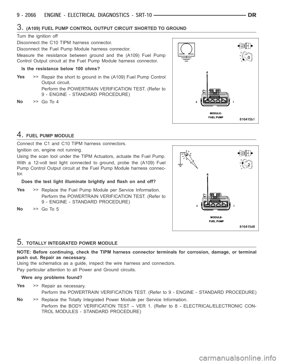
3.(A109) FUEL PUMP CONTROL OUTPUT CIRCUIT SHORTED TO GROUND
Turn the ignition off
Disconnect the C10 TIPM harness connector.
Disconnect the Fuel Pump Module harness connector.
Measure the resistance between ground and the (A109) Fuel Pump
Control Output circuit at the Fuel Pump Module harness connector.
Istheresistancebelow100ohms?
Ye s>>
Repair the short to ground in the (A109) Fuel Pump Control
Output circuit.
Perform the POWERTRAIN VERIFICATION TEST. (Refer to
9 - ENGINE - STANDARD PROCEDURE)
No>>
Go To 4
4.FUEL PUMP MODULE
Connect the C1 and C10 TIPM harness connectors.
Ignition on, engine not running.
Using the scan tool under the TIPM Actuators, actuate the Fuel Pump.
With a 12-volt test light connected to ground, probe the (A109) Fuel
Pump Control Output circuit at the Fuel Pump Module harness connec-
tor.
Does the test light illuminate brightly and flash on and off?
Ye s>>
Replace the Fuel Pump Module per Service Information.
Perform the POWERTRAIN VERIFICATION TEST. (Refer to
9 - ENGINE - STANDARD PROCEDURE)
No>>
Go To 5
5.TOTALLY INTEGRATED POWER MODULE
NOTE: Before continuing, check the TIPM harness connector terminals for corrosion, damage, or terminal
push out. Repair as necessary.
Using the schematics as a guide, inspect the wire harness and connectors.
Pay particular attention to all Power and Ground circuits.
Were any problems found?
Ye s>>
Repair as necessary.
Perform the POWERTRAIN VERIFICATION TEST. (Refer to 9 - ENGINE - STANDARD PROCEDURE)
No>>
Replace the Totally Integrated Power Module per Service Information.
Perform the BODY VERIFICATION TEST – VER 1. (Refer to 8 - ELECTRICAL/ELECTRONIC CON-
TROL MODULES - STANDARD PROCEDURE)
Page 1378 of 5267
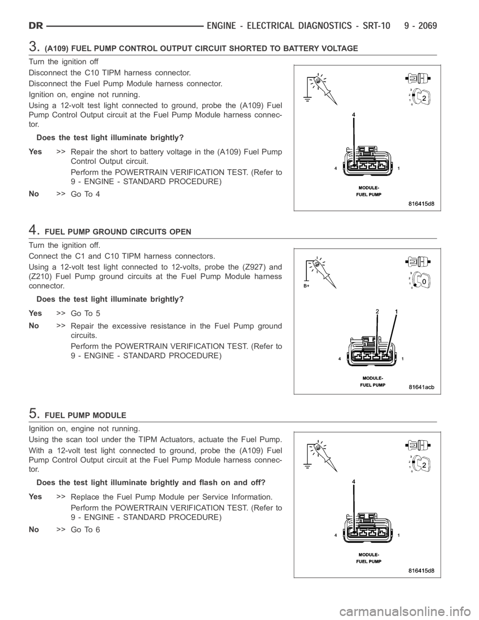
3.(A109) FUEL PUMP CONTROL OUTPUT CIRCUIT SHORTED TO BATTERY VOLTAGE
Turn the ignition off
Disconnect the C10 TIPM harness connector.
Disconnect the Fuel Pump Module harness connector.
Ignition on, engine not running.
Using a 12-volt test light connected to ground, probe the (A109) Fuel
Pump Control Output circuit at the Fuel Pump Module harness connec-
tor.
Does the test light illuminate brightly?
Ye s>>
Repair the short to battery voltage in the (A109) Fuel Pump
Control Output circuit.
Perform the POWERTRAIN VERIFICATION TEST. (Refer to
9 - ENGINE - STANDARD PROCEDURE)
No>>
Go To 4
4.FUEL PUMP GROUND CIRCUITS OPEN
Turn the ignition off.
Connect the C1 and C10 TIPM harness connectors.
Using a 12-volt test light connected to 12-volts, probe the (Z927) and
(Z210) Fuel Pump ground circuits at the Fuel Pump Module harness
connector.
Does the test light illuminate brightly?
Ye s>>
Go To 5
No>>
Repair the excessive resistance in the Fuel Pump ground
circuits.
Perform the POWERTRAIN VERIFICATION TEST. (Refer to
9 - ENGINE - STANDARD PROCEDURE)
5.FUEL PUMP MODULE
Ignition on, engine not running.
Using the scan tool under the TIPM Actuators, actuate the Fuel Pump.
With a 12-volt test light connected to ground, probe the (A109) Fuel
Pump Control Output circuit at the Fuel Pump Module harness connec-
tor.
Does the test light illuminate brightly and flash on and off?
Ye s>>
Replace the Fuel Pump Module per Service Information.
Perform the POWERTRAIN VERIFICATION TEST. (Refer to
9 - ENGINE - STANDARD PROCEDURE)
No>>
Go To 6
Page 1379 of 5267
6.TOTALLY INTEGRATED POWER MODULE
NOTE: Before continuing, check the TIPM harness connector terminals for corrosion, damage, or terminal
push out. Repair as necessary.
Using the schematics as a guide, inspect the wire harness and connectors.
Pay particular attention to all Power and Ground circuits.
Were any problems found?
Ye s>>
Repair as necessary.
Perform the POWERTRAIN VERIFICATION TEST. (Refer to 9 - ENGINE - STANDARD PROCEDURE)
No>>
Replace the Totally Integrated Power Module per Service Information.
Perform the BODY VERIFICATION TEST – VER 1. (Refer to 9 - ENGINE - STANDARD PROCEDURE)
Page 1383 of 5267
5.TOTALLY INTEGRATED POWER MODULE
NOTE: Before continuing, check the TIPM harness connector terminals for corrosion, damage, or terminal
push out. Repair as necessary.
Using the schematics as a guide, inspect the wire harness and connectors.
Pay particular attention to all Power and Ground circuits.
Were any problems found?
Ye s>>
Repair as necessary.
Perform the POWERTRAIN VERIFICATION TEST. (Refer to 9 - ENGINE - STANDARD PROCEDURE)
No>>
Replace the Totally Integrated Power Module in accordance with the Service Information.
Perform the BODY VERIFICATION TEST – VER 1. (Refer to 9 - ENGINE - STANDARD PROCEDURE)
Page 1386 of 5267
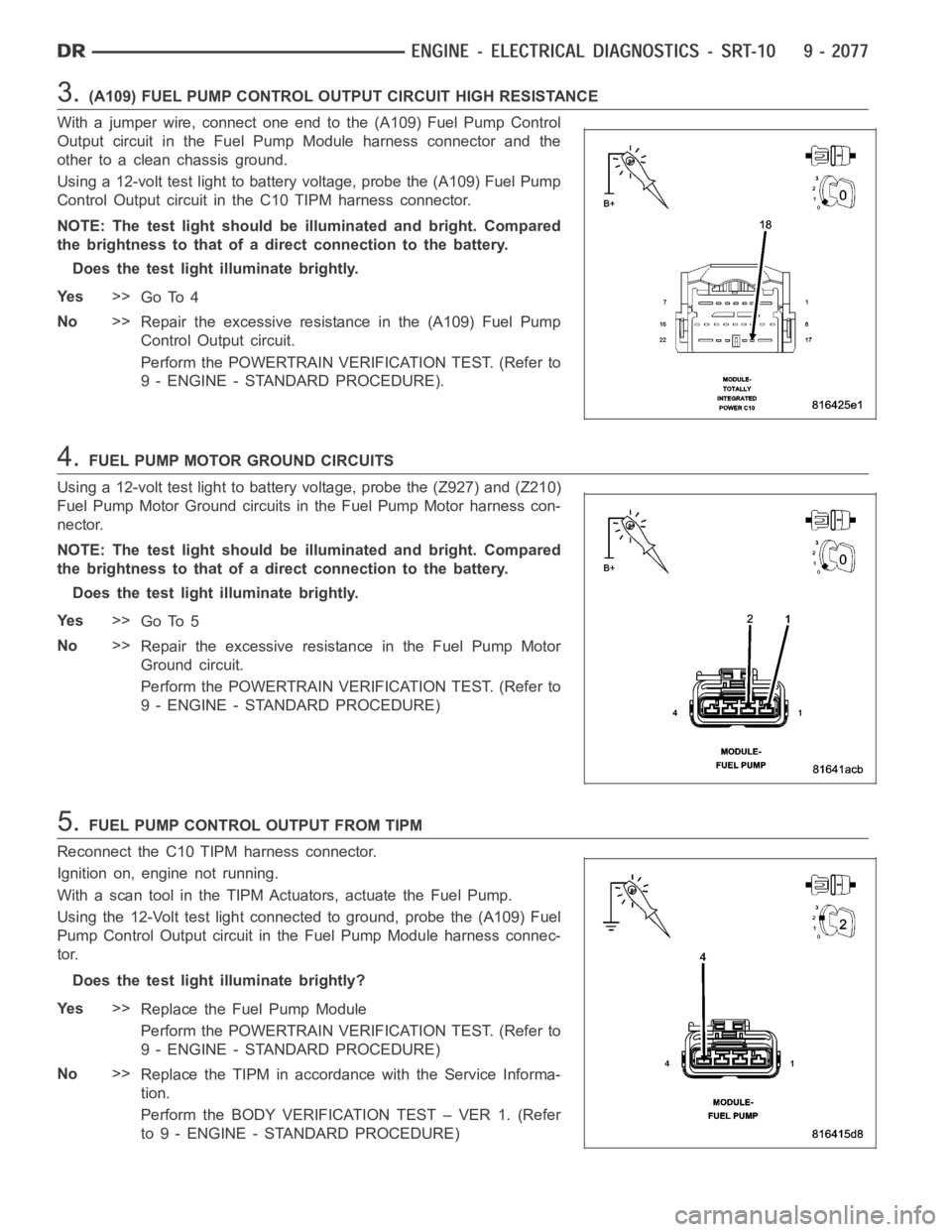
3.(A109) FUEL PUMP CONTROL OUTPUT CIRCUIT HIGH RESISTANCE
With a jumper wire, connect one end to the (A109) Fuel Pump Control
Output circuit in the Fuel Pump Module harness connector and the
other to a clean chassis ground.
Using a 12-volt test light to battery voltage, probe the (A109) Fuel Pump
Control Output circuit in the C10 TIPM harness connector.
NOTE: The test light should be illuminated and bright. Compared
the brightness to that of a direct connection to the battery.
Does the test light illuminate brightly.
Ye s>>
Go To 4
No>>
Repair the excessive resistance in the (A109) Fuel Pump
Control Output circuit.
Perform the POWERTRAIN VERIFICATION TEST. (Refer to
9 - ENGINE - STANDARD PROCEDURE).
4.FUEL PUMP MOTOR GROUND CIRCUITS
Using a 12-volt test light to battery voltage, probe the (Z927) and (Z210)
Fuel Pump Motor Ground circuits in the Fuel Pump Motor harness con-
nector.
NOTE: The test light should be illuminated and bright. Compared
the brightness to that of a direct connection to the battery.
Does the test light illuminate brightly.
Ye s>>
Go To 5
No>>
Repair the excessive resistance in the Fuel Pump Motor
Ground circuit.
Perform the POWERTRAIN VERIFICATION TEST. (Refer to
9 - ENGINE - STANDARD PROCEDURE)
5.FUEL PUMP CONTROL OUTPUT FROM TIPM
Reconnect the C10 TIPM harness connector.
Ignition on, engine not running.
With a scan tool in the TIPM Actuators, actuate the Fuel Pump.
Using the 12-Volt test light connected to ground, probe the (A109) Fuel
Pump Control Output circuit in the Fuel Pump Module harness connec-
tor.
Does the test light illuminate brightly?
Ye s>>
Replace the Fuel Pump Module
Perform the POWERTRAIN VERIFICATION TEST. (Refer to
9 - ENGINE - STANDARD PROCEDURE)
No>>
Replace the TIPM in accordance with the Service Informa-
tion.
Perform the BODY VERIFICATION TEST – VER 1. (Refer
to 9 - ENGINE - STANDARD PROCEDURE)
Page 1387 of 5267
P1281-ENGINE IS COLD TOO LONG
For a complete wiring diagramRefer to Section 8W.
When Monitored:
The ignition key on, engine running.
Set Condition:
The engine does not warm to 176 Deg. F while driving for 20 minutes after start.
Possible Causes
ENGINE COLD TOO LONG
ECT SENSOR OPERATION
Always perform the Pre-Diagnostic Troubleshooting procedure before proceeding. (Refer to 9 - ENGINE -
DIAGNOSIS AND TESTING)
1.CHECK COOLING SYSTEM PERFORMANCE
NOTE: The best way to diagnose this DTC is to allow the vehicle to remain outside overnight in order to
have a completely cold soaked engine.
NOTE: Extremely cold outside ambient temperatures may cause this DTC to set.
Verify that the coolant level is not low and correct as necessary.
Start the engine.
With the scan tool, set the engine RPM to 1500 and allow the engine to warm up for 10-15 minutes.
With the scan tool, monitor the ENG COOLANT TMP DEG value during the warm up cycle. Make sure the transition
of temperature change is smooth.
Did the engine temperature reach a minimum of 80° C (176° F)?
Ye s>>
Go To 2
No>>
Refer to the Service Information for cooling system performance diagnosis. The most probable cause is
a Thermostat problem. Also, refer to any related TSBs.
Perform POWERTRAIN VERIFICATION TEST. (Refer to 9 - ENGINE - STANDARD PROCEDURE)
2.ECT SENSOR OPERATION
WARNING: WARNING: MAKE SURE THE ENGINE COOLING SYSTEM IS COOL BEFORE REMOVING THE
PRESSURE CAP OR ANY HOSE. SEVERE PERSONAL INJURY MAY RESULT FROM ESCAPING HOT COOL-
ANT. THE COOLING SYSTEM IS PRESSURIZED WHEN HOT.
With the scan tool, read and record the ECT Sensor Temperature value.
Using the DRB Temperature Probe #CH7050, measure the engine coolant temperature.
NOTE: The t-stat housing area should be around 192-195 at start to open.
Is the ECT Sensor value with -15°C (5°F) of the temperature probe reading?
Ye s>>
Te s t C o m p l e t e .
No>>
Replace the ECT Sensor.
Perform POWERTRAIN VERIFICATION TEST. (Refer to 9 - ENGINE - STANDARD PROCEDURE)
Page 1390 of 5267
4.(K31) FUEL PUMP RELAY CONTROL CIRCUIT OPEN
Turn the ignition off.
Disconnect the PCM harness connectors.
Measure the resistance of the (K31) Fuel Pump Relay Control circuit from the Fuel Pump Relay connector to the
PCM harness connector.
Is the resistance below 5.0 ohms?
Ye s>>
Go To 5
No>>
Repair the open in the (K31) Fuel Pump Relay Control circuit.
Perform POWERTRAIN VERIFICATION TEST. (Refer to 9 - ENGINE - STANDARD PROCEDURE)
5.(K31) FUEL PUMP RELAY CONTROL CIRCUIT SHORT TO GROUND
Measure the resistance between ground and the (K31) Fuel Pump Relay Control circuit at the PDC.
Istheresistancebelow100ohms?
Ye s>>
Repair the short to ground in the (K31) Fuel Pump Relay Control circuit.
Perform POWERTRAIN VERIFICATION TEST. (Refer to 9 - ENGINE - STANDARD PROCEDURE)
No>>
Go To 6
6.PCM
NOTE: Before continuing, check the PCM harness connector terminals for corrosion, damage, or terminal
push out. Repair as necessary.
Using the schematics as a guide, inspect the wire harness and connectors. Pay particular attention to all Power and
Ground circuits.
If there are no possible causes remaining, view repair.
Repair
Replace and program the Powertrain Control Module per Service Information.
Perform POWERTRAIN VERIFICATION TEST. (Refer to 9 - ENGINE - STANDARD PROCEDURE)
Page 1393 of 5267
4.THROTTLE BODY AND THROTTLE LINKAGE
Inspect the throttle body plate for carbon build up or other restrictions.
Inspect the throttle linkage for binding and smooth operation.
Ensure the throttle plate is resting on the stop at idle.
Remove IAC, inspect the pintle and its seating surface inside the throttlebody.
Were any problems found?
Ye s>>
Clean and/or replace the throttle body as needed.
Perform POWERTRAIN VERIFICATION TEST. (Refer to 9 - ENGINE - STANDARD PROCEDURE)
No>>
Go To 5
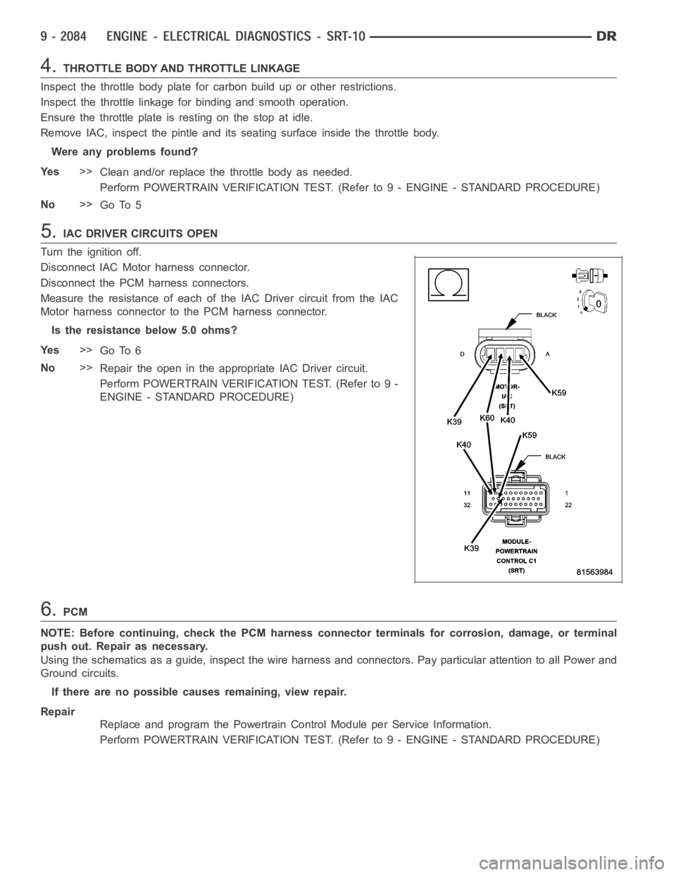
5.IAC DRIVER CIRCUITS OPEN
Turn the ignition off.
Disconnect IAC Motor harness connector.
Disconnect the PCM harness connectors.
Measure the resistance of each of the IAC Driver circuit from the IAC
Motor harness connector to the PCM harness connector.
Is the resistance below 5.0 ohms?
Ye s>>
Go To 6
No>>
Repair the open in the appropriate IAC Driver circuit.
Perform POWERTRAIN VERIFICATION TEST. (Refer to 9 -
ENGINE - STANDARD PROCEDURE)
6.PCM
NOTE: Before continuing, check the PCM harness connector terminals for corrosion, damage, or terminal
push out. Repair as necessary.
Using the schematics as a guide, inspect the wire harness and connectors. Pay particular attention to all Power and
Ground circuits.
If there are no possible causes remaining, view repair.
Repair
Replace and program the Powertrain Control Module per Service Information.
Perform POWERTRAIN VERIFICATION TEST. (Refer to 9 - ENGINE - STANDARD PROCEDURE)