Page 1294 of 5267
5.(K900) SENSOR GROUND CIRCUIT OPEN
Measure the resistance of the (K900) Sensor Ground circuit from the
Fuel Pump Module harness connector to the PCM harness connector.
Is the resistance below 5.0 ohms?
Ye s>>
Go To 6
No>>
Repair the open in the (K900) Sensor Ground circuit.
Perform the POWERTRAIN VERIFICATION TEST. (Refer to
9 - ENGINE - STANDARD PROCEDURE)
6.PCM
NOTE: Before continuing, check the PCM harness connector terminals for corrosion, damage, or terminal
push out. Repair as necessary.
Using the schematics as a guide, inspect the wire harness and connectors. Pay particular attention to all Power and
Ground circuits.
Were there any problems found?
Ye s>>
Repair as necessary.
Perform the POWERTRAIN VERIFICATION TEST. (Refer to 9 - ENGINE - STANDARD PROCEDURE)
No>>
Replace and program the Powertrain Control Module per Service Information.
Perform the POWERTRAIN VERIFICATION TEST. (Refer to 9 - ENGINE - STANDARD PROCEDURE)
Page 1297 of 5267

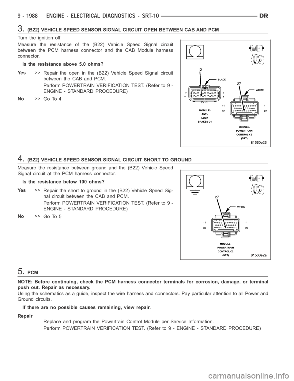
3.(B22) VEHICLE SPEED SENSOR SIGNAL CIRCUIT OPEN BETWEEN CAB AND PCM
Turn the ignition off.
Measure the resistance of the (B22) Vehicle Speed Signal circuit
between the PCM harness connector and the CAB Module harness
connector.
Is the resistance above 5.0 ohms?
Ye s>>
Repair the open in the (B22) Vehicle Speed Signal circuit
between the CAB and PCM.
Perform POWERTRAIN VERIFICATION TEST. (Refer to 9 -
ENGINE - STANDARD PROCEDURE)
No>>
Go To 4
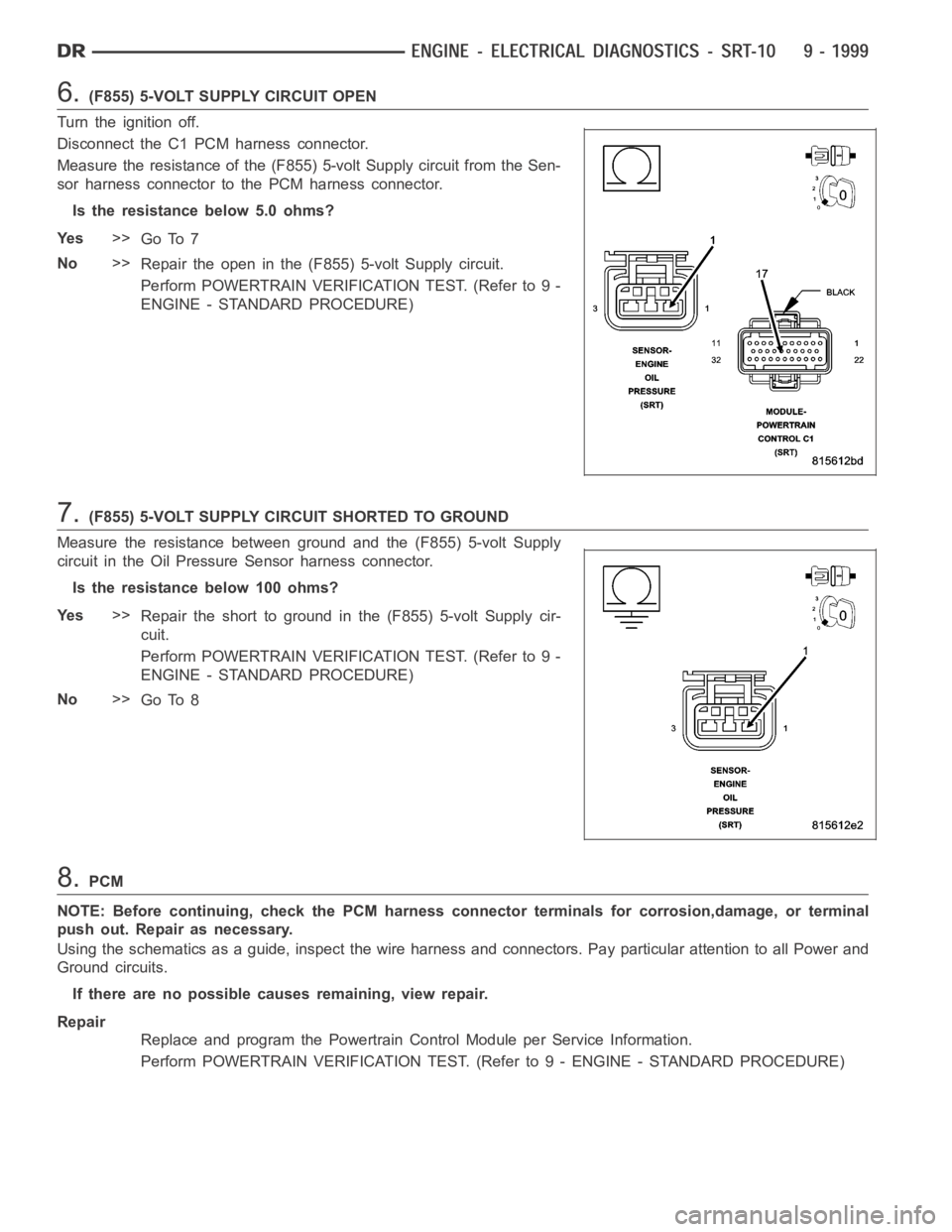
4.(B22) VEHICLE SPEED SENSOR SIGNAL CIRCUIT SHORT TO GROUND
Measure the resistance between ground and the (B22) Vehicle Speed
Signal circuit at the PCM harness connector.
Istheresistancebelow100ohms?
Ye s>>
Repair the short to ground in the (B22) Vehicle Speed Sig-
nal circuit between the CAB and PCM.
Perform POWERTRAIN VERIFICATION TEST. (Refer to 9 -
ENGINE - STANDARD PROCEDURE)
No>>
Go To 5
5.PCM
NOTE: Before continuing, check the PCM harness connector terminals for corrosion, damage, or terminal
push out. Repair as necessary.
Using the schematics as a guide, inspect the wire harness and connectors. Pay particular attention to all Power and
Ground circuits.
If there are no possible causes remaining, view repair.
Repair
Replace and program the Powertrain Control Module per Service Information.
Perform POWERTRAIN VERIFICATION TEST. (Refer to 9 - ENGINE - STANDARD PROCEDURE)
Page 1302 of 5267
7.IAC MOTOR OPERATION
Turn the ignition off.
Connect the C1 PCM harness connectors.
Start and idle the engine.
Using a test light connected to ground, probe the IAC Driver #1 circuit
for 10 seconds.
Repeat the above test for the remaining IAC Motor Driver circuits.
Does the test light turn on and off while probing each IAC
MotorDrivercircuits?
Ye s>>
Replace the Idle Air Control Motor.
Perform POWERTRAIN VERIFICATION TEST. (Refer to 9 -
ENGINE - STANDARD PROCEDURE)
No>>
Replace and program the Powertrain Control Module per
Service Information.
Perform POWERTRAIN VERIFICATION TEST. (Refer to 9 -
ENGINE - STANDARD PROCEDURE)
Page 1304 of 5267
4.GATEWAY MODULE
Turn the ignition off.
Replace and program the Gateway Module in accordance with Service Information.
Ignition on, engine not running.
With the scan tool, erase all SKREEM and PCM DTCs.
Attempt to start and idle the engine.
With the scan tool, read the Gateway Module DTCs.
Does the scan tool display this code?
Ye s>>
NOTE: Before continuing, check the PCM harness connector terminals for corrosion, damage, or termi-
nal push out. Repair as necessary. Replace and program the Powertrain Control Module per Service
Information.
Perform SKREEM VERIFICATION. (Refer to 8 - ELECTRICAL/VEHICLE THEFT SECURITY - STAN-
DARD PROCEDURE)
No>>
Te s t C o m p l e t e .
Page 1308 of 5267

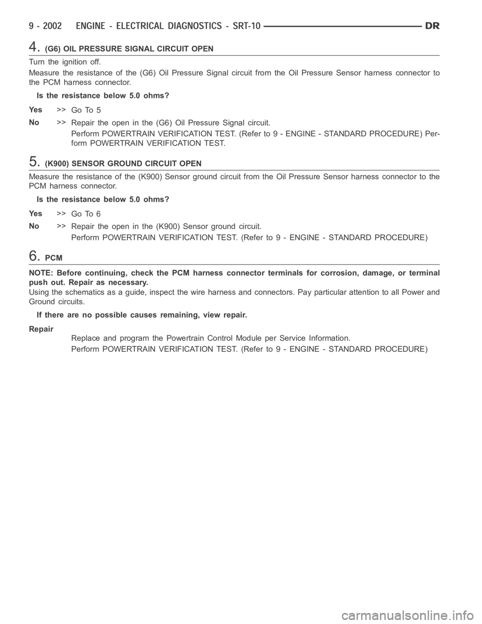
6.(F855) 5-VOLT SUPPLY CIRCUIT OPEN
Turn the ignition off.
Disconnect the C1 PCM harness connector.
Measure the resistance of the (F855) 5-volt Supply circuit from the Sen-
sor harness connector to the PCM harness connector.
Is the resistance below 5.0 ohms?
Ye s>>
Go To 7
No>>
Repair the open in the (F855) 5-volt Supply circuit.
Perform POWERTRAIN VERIFICATION TEST. (Refer to 9 -
ENGINE - STANDARD PROCEDURE)
7.(F855) 5-VOLT SUPPLY CIRCUIT SHORTED TO GROUND
Measure the resistance between ground and the (F855) 5-volt Supply
circuit in the Oil Pressure Sensor harness connector.
Istheresistancebelow100ohms?
Ye s>>
Repair the short to ground in the (F855) 5-volt Supply cir-
cuit.
Perform POWERTRAIN VERIFICATION TEST. (Refer to 9 -
ENGINE - STANDARD PROCEDURE)
No>>
Go To 8
8.PCM
NOTE: Before continuing, check the PCM harness connector terminals for corrosion,damage, or terminal
push out. Repair as necessary.
Using the schematics as a guide, inspect the wire harness and connectors. Pay particular attention to all Power and
Ground circuits.
If there are no possible causes remaining, view repair.
Repair
Replace and program the Powertrain Control Module per Service Information.
Perform POWERTRAIN VERIFICATION TEST. (Refer to 9 - ENGINE - STANDARD PROCEDURE)
Page 1311 of 5267

4.(G6) OIL PRESSURE SIGNAL CIRCUIT OPEN
Turn the ignition off.
Measure the resistance of the (G6) Oil Pressure Signal circuit from the OilPressure Sensor harness connector to
the PCM harness connector.
Is the resistance below 5.0 ohms?
Ye s>>
Go To 5
No>>
Repair the open in the (G6) Oil Pressure Signal circuit.
Perform POWERTRAIN VERIFICATION TEST. (Refer to 9 - ENGINE - STANDARD PROCEDURE) Per-
form POWERTRAIN VERIFICATION TEST.
5.(K900) SENSOR GROUND CIRCUIT OPEN
Measure the resistance of the (K900) Sensor ground circuit from the Oil Pressure Sensor harness connector to the
PCM harness connector.
Is the resistance below 5.0 ohms?
Ye s>>
Go To 6
No>>
Repair the open in the (K900) Sensor ground circuit.
Perform POWERTRAIN VERIFICATION TEST. (Refer to 9 - ENGINE - STANDARD PROCEDURE)
6.PCM
NOTE: Before continuing, check the PCM harness connector terminals for corrosion, damage, or terminal
push out. Repair as necessary.
Using the schematics as a guide, inspect the wire harness and connectors. Pay particular attention to all Power and
Ground circuits.
If there are no possible causes remaining, view repair.
Repair
Replace and program the Powertrain Control Module per Service Information.
Perform POWERTRAIN VERIFICATION TEST. (Refer to 9 - ENGINE - STANDARD PROCEDURE)
Page 1312 of 5267
P0601-PCM INTERNAL CONTROLLER FAILURE
For a complete wiring diagramRefer to Section 8W.
When Monitored:
With the ignition on.
Set Condition:
Internal checksum for software failed, does not match calculated value. One Trip Fault, Three Good Trips to
clear.
Possible Causes
PCM
Always perform the Pre-Diagnostic Troubleshooting procedure before proceeding. (Refer to 9 - ENGINE -
DIAGNOSIS AND TESTING).
Diagnostic Test
1.PCM
NOTE: Diagnose any CMP or CKP Sensor faults before continuing. Check for intermittent loose CMP or CKP
connections.
The Powertrain Control Module is reporting internal errors, view repair to continue.
Repair
Replace and program the Powertrain Control Module per Service Information.
Perform the POWERTRAIN VERIFICATION TEST. (Refer to 9 - ENGINE - STANDARD PROCEDURE)
Page 1316 of 5267
6.PCM
NOTE: Before continuing, check the PCM harness connector terminals for corrosion, damage, or terminal
push out. Repair as necessary.
Using the schematics as a guide, inspect the wire harness and connectors. Pay particular attention to all Power and
Ground circuits.
If there are no possible causes remaining, view repair.
Repair
Replace and program the Powertrain Control Module per Service Information.
Perform POWERTRAIN VERIFICATION TEST. (Refer to 9 - ENGINE - STANDARD PROCEDURE)