2006 DODGE RAM SRT-10 wheel torque
[x] Cancel search: wheel torquePage 2026 of 5267
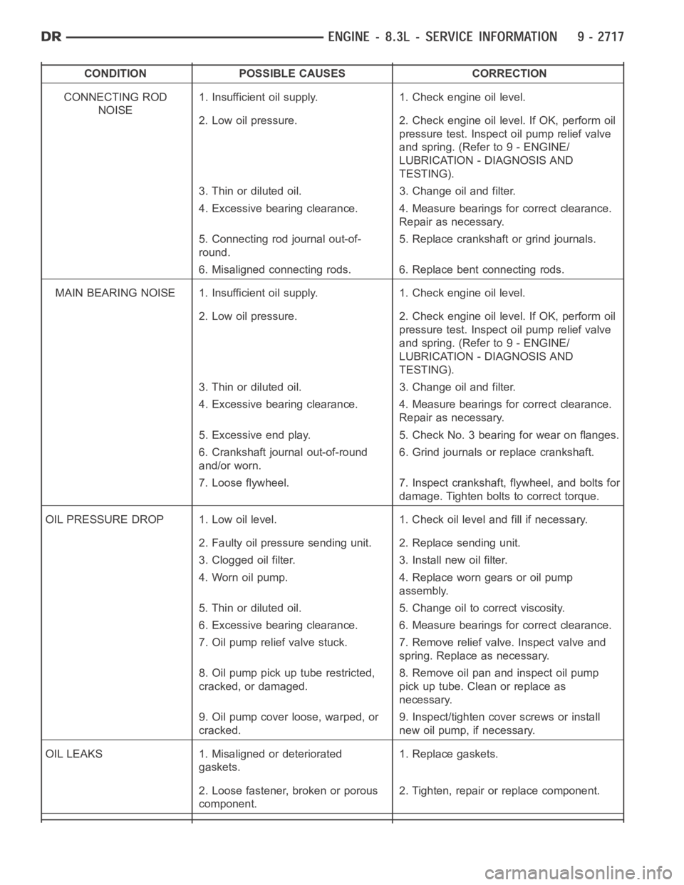
CONDITION POSSIBLE CAUSES CORRECTION
CONNECTING ROD
NOISE1. Insufficient oil supply. 1. Check engine oil level.
2. Low oil pressure. 2. Check engine oil level. If OK, perform oil
pressure test. Inspect oil pump relief valve
and spring. (Refer to 9 - ENGINE/
LUBRICATION - DIAGNOSIS AND
TESTING).
3. Thin or diluted oil. 3. Change oil and filter.
4. Excessive bearing clearance. 4. Measure bearings for correct clearance.
Repair as necessary.
5. Connecting rod journal out-of-
round.5. Replace crankshaft or grind journals.
6. Misaligned connecting rods. 6. Replace bent connecting rods.
MAIN BEARING NOISE 1. Insufficient oil supply. 1. Check engine oil level.
2. Low oil pressure. 2. Check engine oil level. If OK, perform oil
pressure test. Inspect oil pump relief valve
and spring. (Refer to 9 - ENGINE/
LUBRICATION - DIAGNOSIS AND
TESTING).
3. Thin or diluted oil. 3. Change oil and filter.
4. Excessive bearing clearance. 4. Measure bearings for correct clearance.
Repair as necessary.
5. Excessive end play. 5. Check No. 3 bearing for wear on flanges.
6. Crankshaft journal out-of-round
and/or worn.6. Grind journals or replace crankshaft.
7. Loose flywheel. 7. Inspect crankshaft, flywheel, and bolts for
damage. Tighten bolts to correct torque.
OIL PRESSURE DROP 1. Low oil level. 1. Check oil level and fill if necessary.
2. Faulty oil pressure sending unit. 2. Replace sending unit.
3. Clogged oil filter. 3. Install new oil filter.
4. Worn oil pump. 4. Replace worn gears or oil pump
assembly.
5. Thin or diluted oil. 5. Change oil to correct viscosity.
6. Excessive bearing clearance. 6. Measure bearings for correct clearance.
7. Oil pump relief valve stuck. 7. Remove relief valve. Inspect valve and
spring. Replace as necessary.
8. Oil pump pick up tube restricted,
cracked, or damaged.8. Remove oil pan and inspect oil pump
pick up tube. Clean or replace as
necessary.
9. Oil pump cover loose, warped, or
cracked.9. Inspect/tighten cover screws or install
new oil pump, if necessary.
OIL LEAKS 1. Misaligned or deteriorated
gaskets.1. Replace gaskets.
2. Loose fastener, broken or porous
component.2. Tighten, repair or replace component.
Page 2045 of 5267
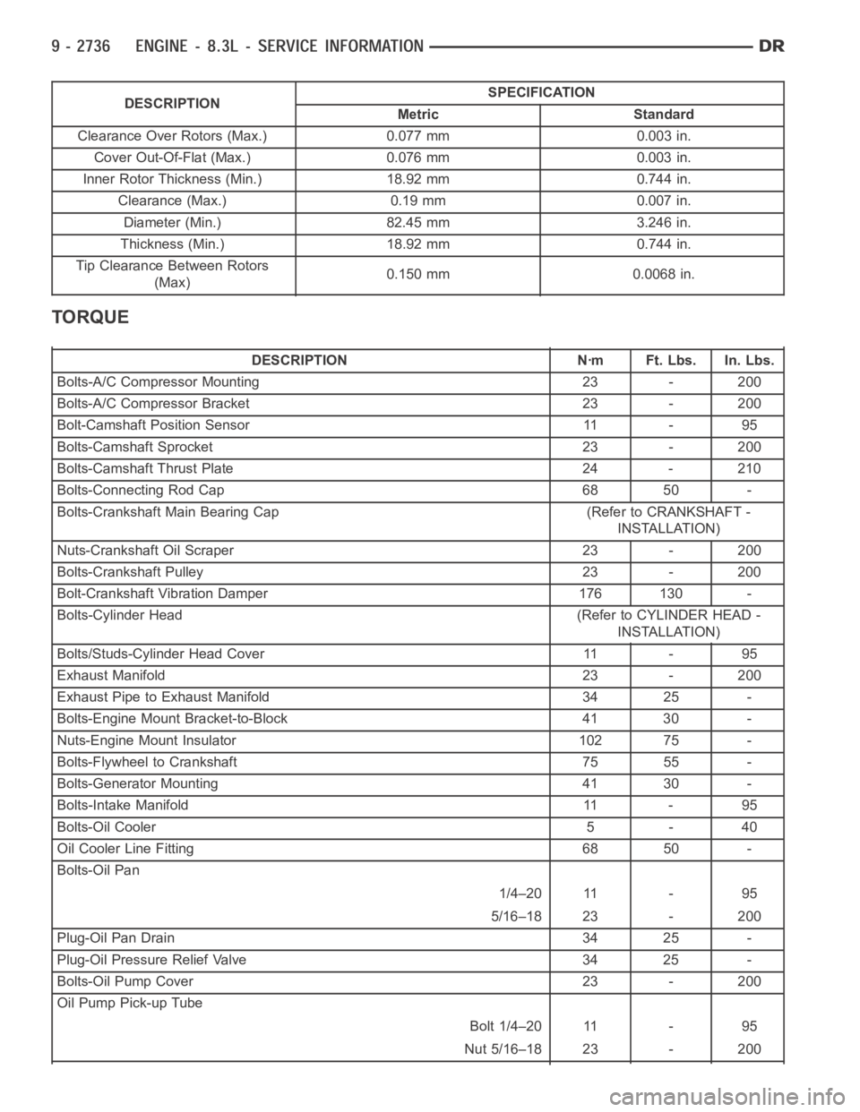
DESCRIPTIONSPECIFICATION
Metric Standard
Clearance Over Rotors (Max.) 0.077 mm 0.003 in.
Cover Out-Of-Flat (Max.) 0.076 mm 0.003 in.
Inner Rotor Thickness (Min.) 18.92 mm 0.744 in.
Clearance (Max.) 0.19 mm 0.007 in.
Diameter (Min.) 82.45 mm 3.246 in.
Thickness (Min.) 18.92 mm 0.744 in.
Tip Clearance Between Rotors
(Max)0.150 mm 0.0068 in.
TORQUE
DESCRIPTION Nꞏm Ft. Lbs. In. Lbs.
Bolts-A/C Compressor Mounting 23 - 200
Bolts-A/C Compressor Bracket 23 - 200
Bolt-Camshaft Position Sensor 11 - 95
Bolts-Camshaft Sprocket 23 - 200
Bolts-Camshaft Thrust Plate 24 - 210
Bolts-Connecting Rod Cap 68 50 -
Bolts-Crankshaft Main Bearing Cap (Refer to CRANKSHAFT -
INSTALLATION)
Nuts-Crankshaft Oil Scraper 23 - 200
Bolts-Crankshaft Pulley 23 - 200
Bolt-Crankshaft Vibration Damper 176 130 -
Bolts-Cylinder Head (Refer to CYLINDER HEAD -
INSTALLATION)
Bolts/Studs-Cylinder Head Cover 11 - 95
Exhaust Manifold 23 - 200
Exhaust Pipe to Exhaust Manifold 34 25 -
Bolts-Engine Mount Bracket-to-Block 41 30 -
Nuts-Engine Mount Insulator 102 75 -
Bolts-Flywheel to Crankshaft 75 55 -
Bolts-Generator Mounting 41 30 -
Bolts-Intake Manifold 11 - 95
Bolts-Oil Cooler 5 - 40
Oil Cooler Line Fitting 68 50 -
Bolts-Oil Pan
1/4–20 11 - 95
5/16–18 23 - 200
Plug-Oil Pan Drain 34 25 -
Plug-Oil Pressure Relief Valve 34 25 -
Bolts-Oil Pump Cover 23 - 200
Oil Pump Pick-up Tube
Bolt 1/4–20 11 - 95
Nut 5/16–18 23 - 200
Page 2081 of 5267

5. Hand start bolts No.1 and No.2.
6. Loosely install A/C compressor mounting bracket.
7. Hand start remaining timing chain cover bolts.
8. Torque timing chain cover bolts in the sequence
showninto23Nꞏm(200in.lbs.).
9. Torque A/C compressor mounting bracket bolts to
23 Nꞏm (200 in. lbs.).
10. Install crankshaft oil seal (Refer to 9 - ENGINE/
ENGINE BLOCK/CRANKSHAFT OIL SEAL -
FRONT - INSTALLATION).
11. Raise vehicle on hoist.
12. Install oil pump pick up tube using anewo-ring.
Torque 1/4–20 bolt to 11 Nꞏm (95 in. lbs.). Torque
5/16–18 nuts to 23 Nꞏm (200 in. lbs.).
13. Support the engine with a jack stand.
14. Install oil pan and drain plug (Refer to 9 -
ENGINE/LUBRICATION/OIL PAN - INSTALLA-
TION).
15. Remove the jackstand.
16. Tighten the engine mount to frame nuts to 102
Nꞏm (75 ft.lbs.).
17. Connect the oil cooler coolant hose to the timing
cover.
18. Connect the oil cooler line (Refer to 9 - ENGINE/
LUBRICATION/OIL COOLER & LINES - STAN-
DARD PROCEDURE).
19. Install the lower radiator hose.
20. Install the flywheel inspection cover.
21. Install the front frame cross member (Refer to 13
- FRAME & BUMPERS/FRAME/FRONT CROSS-
MEMBER - INSTALLATION).
22. Lower vehicle.
23. Position the compressor and install A/C compressor mounting bolts. Torque bolts to 23 Nꞏm (200 in. lbs.).
24. Connect heater hose at timing cover.
25. Install crankshaft damper and pulley (Refer to 9 - ENGINE/ENGINE BLOCK/VIBRATION DAMPER - INSTAL-
LATION).
26. Install generator. Connect electrical connectors.
27. Install the idler pulley.
28. Connect the camshaft position sensor wiring harness connector.
29. Connect engine coolant temperature (ECT) sensor wiring harness connector.
30. Install power steering pump mounting bolts.
31. Install accessory drive belt (Refer to 7 - COOLING/ACCESSORY DRIVE/DRIVE BELTS - INSTALLATION).
32. Install the radiator fan assembly (Refer to 7 - COOLING/ENGINE/RADIATOR FAN - INSTALLATION).
Page 2095 of 5267
2. Apply an 1/8 in. bead of Mopar Engine RTV at the two joints between the cylinder block to timing chain case
cover and the two joints between the rear main seal retainer and engine block.
3. Position oil pan and gasket to engine block, seat the oil level indicatortube in the oil pan and hand start all
fasteners.
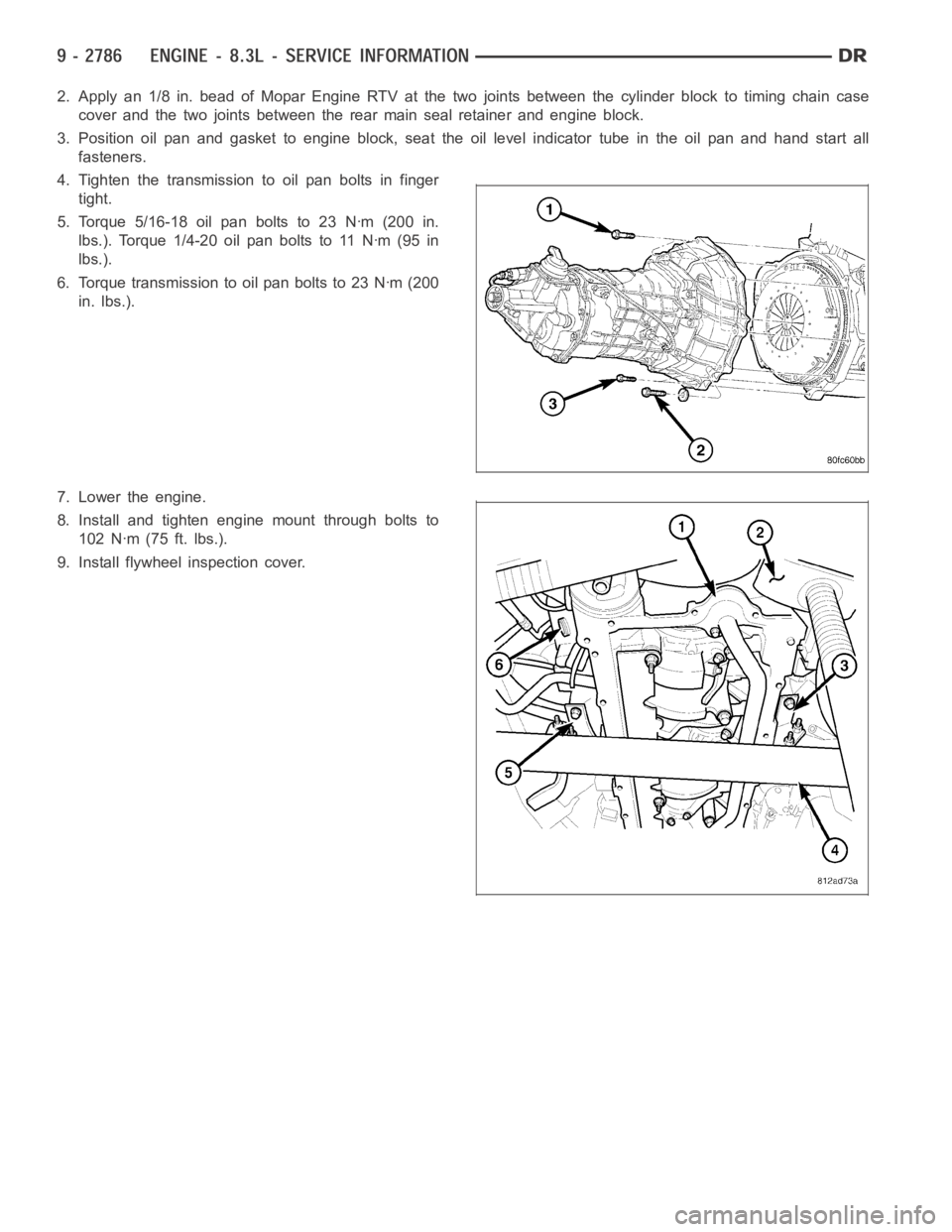
4. Tighten the transmission to oil pan bolts in finger
tight.
5. Torque 5/16-18 oil pan bolts to 23 Nꞏm (200 in.
lbs.). Torque 1/4-20 oil pan bolts to 11 Nꞏm (95 in
lbs.).
6. Torque transmission to oil pan bolts to 23 Nꞏm (200
in. lbs.).
7. Lower the engine.
8. Install and tighten engine mount through bolts to
102 Nꞏm (75 ft. lbs.).
9. Install flywheel inspection cover.
Page 2166 of 5267
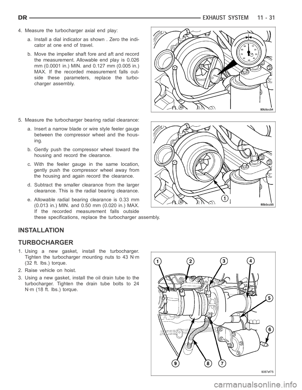
4. Measure the turbocharger axial end play:
a. Install a dial indicator as shown . Zero the indi-
cator at one end of travel.
b. Move the impeller shaft fore and aft and record
the measurement. Allowable end play is 0.026
mm (0.0001 in.) MIN. and 0.127 mm (0.005 in.)
MAX. If the recorded measurement falls out-
side these parameters, replace the turbo-
charger assembly.
5. Measure the turbocharger bearing radial clearance:
a. Insert a narrow blade or wire style feeler gauge
between the compressor wheel and the hous-
ing.
b. Gently push the compressor wheel toward the
housing and record the clearance.
c. With the feeler gauge in the same location,
gently push the compressor wheel away from
the housing and again record the clearance.
d. Subtract the smaller clearance from the larger
clearance. This is the radial bearing clearance.
e. Allowable radial bearing clearance is 0.33 mm
(0.013 in.) MIN. and 0.50 mm (0.020 in.) MAX.
If the recorded measurement falls outside
these specifications, replace the turbocharger assembly.
INSTALLATION
TURBOCHARGER
1. Using a new gasket, install the turbocharger.
Tighten the turbocharger mounting nuts to 43 Nꞏm
(32 ft. lbs.) torque.
2. Raise vehicle on hoist.
3. Using a new gasket, install the oil drain tube to the
turbocharger. Tighten the drain tube bolts to 24
Nꞏm (18 ft. lbs.) torque.
Page 2242 of 5267

8. Connect other end of jumper wire to positive side of battery.
9. Connect one end of a second jumper wire to remaining injector terminal.
CAUTION: Powering an injector for more than a few seconds will permanentlydamage the injector.
10. Momentarily touch other end of jumper wire to negative terminal of battery for no more than a few seconds.
11. Place a rag or towel below fuel line quick-connect fitting at fuel rail.
12. Disconnect quick-connect fitting at fuel rail. Refer to Quick-Connect Fittings.
13. Return fuel pump relay to PDC.
14. One or more Diagnostic Trouble Codes (DTC’s) may have been stored in PCMmemory due to fuel pump relay
removal. The DRB
scantoolmustbeusedtoeraseaDTC.
STANDARD PROCEDURE - DRAINING FUEL TANK - EXCEPT DIESEL
WARNING: The fuel system may be under constant fuel pressure even with the engine off. This pressure
must be released before servicing fuel tank.
Two different procedures may be used to drain fuel tank: through the fuel fill fitting on tank, or using a diagnostic
scan tool to activate the fuel pump relay. Due to a one-way check valve installed into the fuel fill opening fitting at
the tank, the tank cannot be drained conventionally at the fill cap.
The quickest draining procedure involves removing the rubber fuel fill hose at the fuel tank.
As an alternative procedure, the electric fuel pump may be activated allowingtanktobedrainedatfuelrailcon-
nection. Refer to diagnostic scan tool for fuel pump activation procedures. Before disconnecting fuel line at fuel rail,
release fuel pressure. Refer to the Fuel System Pressure Release Procedure for procedures. Attach end of special
test hose tool number 6631 or 6539 at fuel rail disconnection (tool number 6631isusedon5/16”fuellineswhile
tool number 6539 is used on 3/8” fuel lines). Position opposite end of this hose tool to an approved gasoline drain-
ing station. Activate fuel pump and drain tank until empty.
If electric fuel pump is not operating, fuel must be drained through fuel fill fitting at tank. Refer to following proce-
dures.
1. Release fuel system pressure.
2. Raise vehicle.
3. Thoroughly clean area around fuel fill fitting and rubber fuel fill hoseat tank.
4. If vehicle is equipped with 4 doors and a 6 foot (short) box, remove left-rear tire/wheel.
5. Loosen clamp and disconnect rubber fuel fill hose at tank fitting. Usingan approved gas holding tank, drain fuel
tank through this fitting.
SPECIFICATIONS
FUEL SYSTEM PRESSURE
58 psi +/- 2 psi
TORQUE - EXCEPT DIESEL
DESCRIPTION N-m Ft. Lbs. In. Lbs.
Accelerator Pedal Bracket
Mounting12 - 105
Accelerator Pedal Position
Sensor Bracket-to-Battery
Tray Bolts3-30
Crankshaft Position
Sensor - 3.7L28 21 -
Crankshaft Position
Sensor - 4.7L28 21 -
Page 2344 of 5267
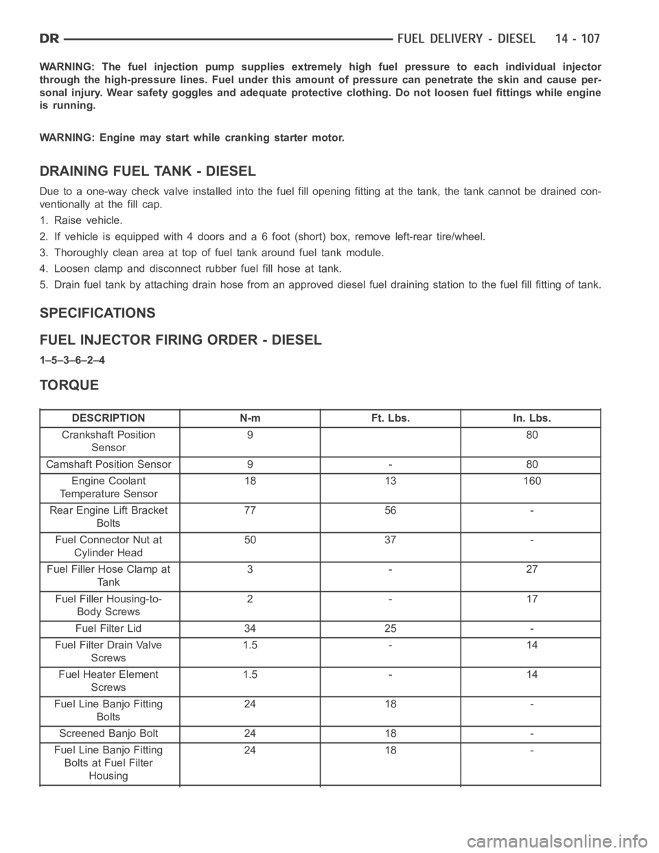
WARNING: The fuel injection pump supplies extremely high fuel pressure toeach individual injector
through the high-pressure lines. Fuel under this amount of pressure can penetrate the skin and cause per-
sonal injury. Wear safety goggles and adequate protective clothing. Do not loosen fuel fittings while engine
is running.
WARNING: Engine may start while cranking starter motor.
DRAINING FUEL TANK - DIESEL
Due to a one-way check valve installed into the fuel fill opening fitting atthe tank, the tank cannot be drained con-
ventionally at the fill cap.
1. Raise vehicle.
2. If vehicle is equipped with 4 doors and a 6 foot (short) box, remove left-rear tire/wheel.
3. Thoroughly clean area at top of fuel tank around fuel tank module.
4. Loosen clamp and disconnect rubber fuel fill hose at tank.
5. Drain fuel tank by attaching drain hose from an approved diesel fuel draining station to the fuel fill fitting of tank.
SPECIFICATIONS
FUEL INJECTOR FIRING ORDER - DIESEL
1–5–3–6–2–4
TORQUE
DESCRIPTION N-m Ft. Lbs. In. Lbs.
Crankshaft Position
Sensor980
Camshaft Position Sensor 9 - 80
Engine Coolant
Temperature Sensor18 13 160
Rear Engine Lift Bracket
Bolts77 56 -
Fuel Connector Nut at
Cylinder Head50 37 -
Fuel Filler Hose Clamp at
Ta n k3-27
Fuel Filler Housing-to-
Body Screws2-17
Fuel Filter Lid 34 25 -
Fuel Filter Drain Valve
Screws1.5 - 14
Fuel Heater Element
Screws1.5 - 14
Fuel Line Banjo Fitting
Bolts24 18 -
Screened Banjo Bolt 24 18 -
Fuel Line Banjo Fitting
Bolts at Fuel Filter
Housing24 18 -
Page 2412 of 5267
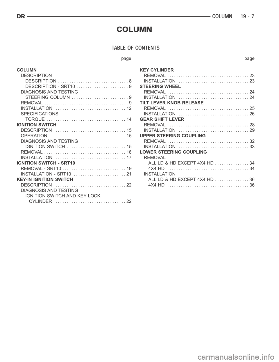
page page
COLUMN
DESCRIPTION
DESCRIPTION ............................... 8
DESCRIPTION - SRT10 ....................... 9
DIAGNOSIS AND TESTING
STEERING COLUMN ......................... 9
REMOVAL ..................................... 9
INSTALLATION ............................... 12
SPECIFICATIONS
TORQUE ................................... 14
IGNITION SWITCH
DESCRIPTION ................................ 15
OPERATION .................................. 15
DIAGNOSIS AND TESTING
IGNITION SWITCH .......................... 15
REMOVAL .................................... 16
INSTALLATION ............................... 17
IGNITION SWITCH - SRT10
REMOVAL - SRT10 ............................ 19
INSTALLATION - SRT10 ....................... 21
KEY-IN IGNITION SWITCH
DESCRIPTION ................................ 22
DIAGNOSIS AND TESTING
IGNITION SWITCH AND KEY LOCK
CYLINDER................................. 22KEY CYLINDER
REMOVAL .................................... 23
INSTALLATION ............................... 23
STEERING WHEEL
REMOVAL .................................... 24
INSTALLATION ............................... 24
TILT LEVER KNOB RELEASE
REMOVAL .................................... 25
INSTALLATION ............................... 26
GEAR SHIFT LEVER
REMOVAL .................................... 28
INSTALLATION ............................... 29
UPPER STEERING COUPLING
REMOVAL .................................... 32
INSTALLATION ............................... 33
LOWER STEERING COUPLING
REMOVAL
ALL LD & HD EXCEPT 4X4 HD ............... 34
4X4 HD .................................... 34
INSTALLATION
ALL LD & HD EXCEPT 4X4 HD ............... 36
4X4 HD .................................... 36