2006 DODGE RAM SRT-10 brake light
[x] Cancel search: brake lightPage 1483 of 5267
POWERTRAIN VERIFICATION TEST
For a complete wiring diagramRefer to Section 8W.
Diagnostic Test
1.SELECTING THE PROPER VERIFICATION TEST
The following verification test are for different repairs. Select the appropriate Verification test for the
repair that has been completed.
Speed Control repair
Go To 2
Charging System repair
Go To 3
NVLD System repair
Go To 4
All other repairs
Go To 5
2.POWERTRAIN VERIFICATION TEST 1
NOTE: 1. If this vehicle is equipped with an Electronic Throttle Control system, and the APP Sensors, PCM,
or Throttle Body Assembly have been replaced, use the scan tool to perform the ETC RELEARN function.
NOTE: 2. After completing the Powertrain Verification Test the Transmission Verification Test must be per-
formed.
NOTE: 3. If the PCM has been replaced and the correct VIN and mileage have notbeen programmed, a DTC
will set in the ABS Module, Airbag Module and the SKIM/SKREEM.
NOTE: 4. If the vehicle is equipped with a Sentry Key Remote Entry, Secret Key data must be updated. Refer
to the Service Information for the PCM, SKIM/SKREEM and the Transponder (ignition key) for programming
information. Using the scan tool, program the Secret Key information intothe PCM using the PCM replaced
function under the WCM menu.
5. Inspect the vehicle to make sure that all engine components are properlyinstalled and connected.
6. Connect the scan tool to the data link connector and erase all codes.
7. Turn the speed control ON (if equipped, cruise light will be on).
8. Depress and release the SET Switch when the vehicle speed is greater than35 MPH. The speed control should
engage and hold the selected speed.
9. Press and hold the RESUME/ACCEL Switch. The vehicle speed should increase by at least 2 MPH.
10. Press and hold the COAST switch. The vehicle speed should decrease.
11. Using caution, press and release the brake pedal. The speed control should disengage.
12. Bring the vehicle speed back up to 35 MPH.
13. Press the RESUME/ACCEL switch. The speed control should resume the previously set speed.
14. Hold down the SET switch. The vehicle should decelerate.
15. Make sure vehicle speed is greater than 35 mph and release the SET Switch. The vehicle should adjust and set
a new vehicle speed.
16. Press and release the CANCEL switch. The speed control should disengage.
17. Bring the vehicle speed back up above 35 mph and engage speed control.
18. Turn the Speed Control Off. (Cruise light will be off). The speed control should disengage.
NOTE: OVERSHOOT/UNDERSHOOT FOLLOWING SPEED CONTROL SET.
19. If the vehicle operator repeatedly presses and releases the SET buttonwith their foot off of the accelerator
(referred to as
lift foot set), the vehicle may accelerate and exceed the desired set speed by up to 5 mph (8km/h).
20. It may also decelerate to less than the desired set speed, before finally achieving the desired set speed.
21. The Speed Control System has an adaptive strategy that compensates forvehicle-to-vehicle variations in speed
control cable lengths.
22. When the speed control is set with the vehicles operators foot off of theaccelerator pedal, the speed control
thinks there is excessive speed control cable slack and adapts accordingly.
Page 2104 of 5267
BLOCK-ENGINE
DESCRIPTION
The cylinder block is made of a sand-cast aluminum alloy. The cylinder block has interference-fit cast iron cylinder
liners. The cylinder liners are thermally installed during block manufacturing; they are not serviceable items.
Six iron main bearing caps use four bolts per cap; two vertical and two horizontal. A crankshaft oil scraper is
attached to the main bearing caps via extended main bearing cap bolts and nuts.
STANDARD PROCEDURE - CYLINDER BORE HONING
Before honing, stuff plenty of clean shop towels under
the bores and over the crankshaft to keep abrasive
materials from entering the crankshaft area.
1. Used carefully, the Cylinder Bore Sizing Hone
C-823, equipped with 220 grit stones, is the best
tool for this job. In addition to deglazing, it will
reduce taper and out-of-round, as well as removing
light scuffing, scoring and scratches. Usually, a few
strokes will clean up a bore and maintain the
required limits.
CAUTION: DO NOT use rigid type hones to remove
cylinder wall glaze.
2. Deglazing of the cylinder walls may be done if the
cylinder bore is straight and round. Use a cylinder
surfacing hone, Honing Tool C-3501, equipped with
280 grit stones (C-3501-3810). about 20-60
strokes, depending on the bore condition, will be
sufficient to provide a satisfactory surface. Using
honing oil C-3501-3880, or a light honing oil, avail-
able from major oil distributors.
CAUTION: DO NOT use engine or transmission oil, mineral spirits, or kerosene.
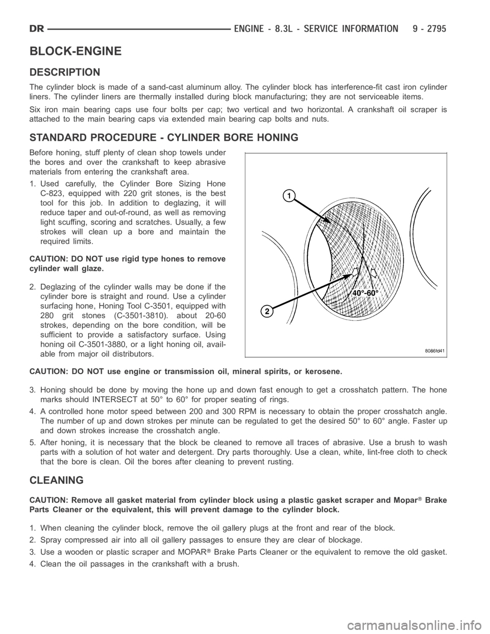
3. Honing should be done by moving the hone up and down fast enough to get a crosshatch pattern. The hone
marks should INTERSECT at 50° to 60° for proper seating of rings.
4. A controlled hone motor speed between 200 and 300 RPM is necessary to obtain the proper crosshatch angle.
The number of up and down strokes per minute can be regulated to get the desired 50° to 60° angle. Faster up
and down strokes increase the crosshatch angle.
5. After honing, it is necessary that the block be cleaned to remove all traces of abrasive. Use a brush to wash
parts with a solution of hot water and detergent. Dry parts thoroughly. Usea clean, white, lint-free cloth to check
that the bore is clean. Oil the bores after cleaning to prevent rusting.
CLEANING
CAUTION: Remove all gasket material from cylinder block using a plastic gasket scraper and MoparBrake
Parts Cleaner or the equivalent, this will prevent damage to the cylinder block.
1. When cleaning the cylinder block, remove the oil gallery plugs at the front and rear of the block.
2. Spray compressed air into all oil gallery passages to ensure they are clear of blockage.
3. Use a wooden or plastic scraper and MOPAR
Brake Parts Cleaner or the equivalent to remove the old gasket.
4. Clean the oil passages in the crankshaft with a brush.
Page 2358 of 5267
1. Inspect pump mounting surfaces at pump and
mounting flange and pilot bore for nicks, cuts or
damage. Inspect O-ring surfaces for nicks, cuts or
damage.
2. Clean injection pump mounting flange and pilot
bore at gear housing. Also clean front of injection
pump.
3. Install new rubber O-ring (square) into machined
groove at pump mounting area.
4. Apply clean engine oilto injection pump O-ring
and pilot bore only.
The machined tapers on both injection pump shaft
and injection pump gear must be absolutely dry, clean and free of any dirt oroil film. This will ensure
proper gear-to-shaft tightening.
5. Clean pump gear and pump shaft at machined tapers with an evaporative type cleaner such as brake cleaner.
6. Position injection pump to mounting flange on gear housing while aligning injection pump shaft through back of
injection pump gear.
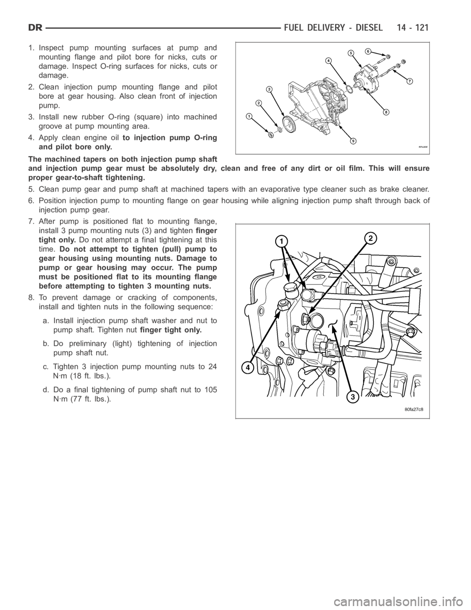
7. After pump is positioned flat to mounting flange,
install 3 pump mounting nuts (3) and tightenfinger
tight only.Do not attempt a final tightening at this
time.Do not attempt to tighten (pull) pump to
gear housing using mounting nuts. Damage to
pump or gear housing may occur. The pump
must be positioned flat to its mounting flange
before attempting to tighten 3 mounting nuts.
8. To prevent damage or cracking of components,
install and tighten nuts in the following sequence:
a. Install injection pump shaft washer and nut to
pump shaft. Tighten nutfinger tight only.
b. Do preliminary (light) tightening of injection
pump shaft nut.
c. Tighten 3 injection pump mounting nuts to 24
Nꞏm (18 ft. lbs.).
d. Do a final tightening of pump shaft nut to 105
Nꞏm (77 ft. lbs.).
Page 2416 of 5267
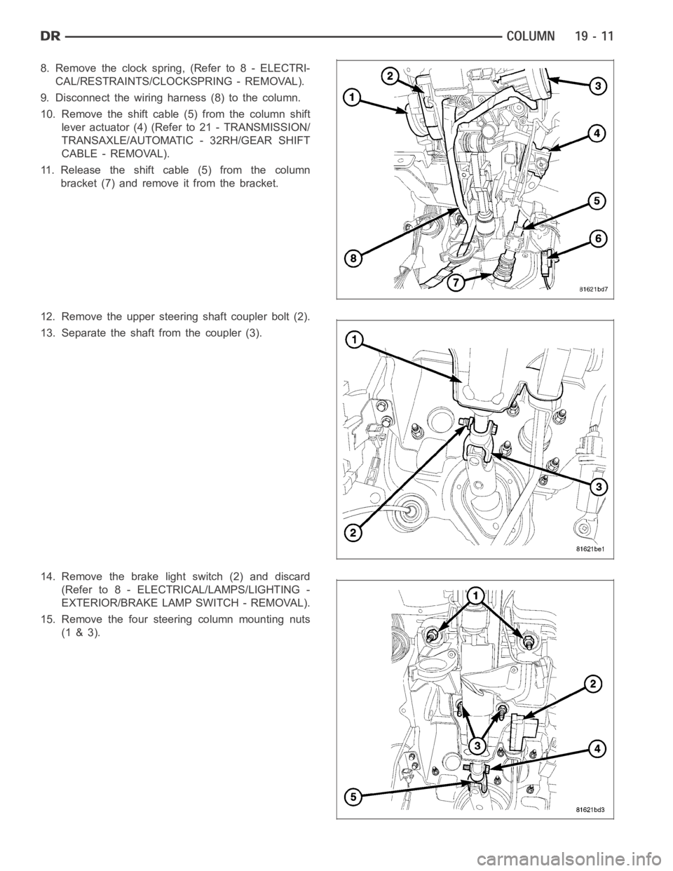
8. Remove the clock spring, (Refer to 8 - ELECTRI-
CAL/RESTRAINTS/CLOCKSPRING - REMOVAL).
9. Disconnect the wiring harness (8) to the column.
10. Remove the shift cable (5) from the column shift
lever actuator (4) (Refer to 21 - TRANSMISSION/
TRANSAXLE/AUTOMATIC - 32RH/GEAR SHIFT
CABLE - REMOVAL).
11. Release the shift cable (5) from the column
bracket (7) and remove it from the bracket.
12. Remove the upper steering shaft coupler bolt (2).
13. Separate the shaft from the coupler (3).
14. Remove the brake light switch (2) and discard
(Refer to 8 - ELECTRICAL/LAMPS/LIGHTING -
EXTERIOR/BRAKE LAMP SWITCH - REMOVAL).
15. Remove the four steering column mounting nuts
(1 & 3).
Page 2417 of 5267
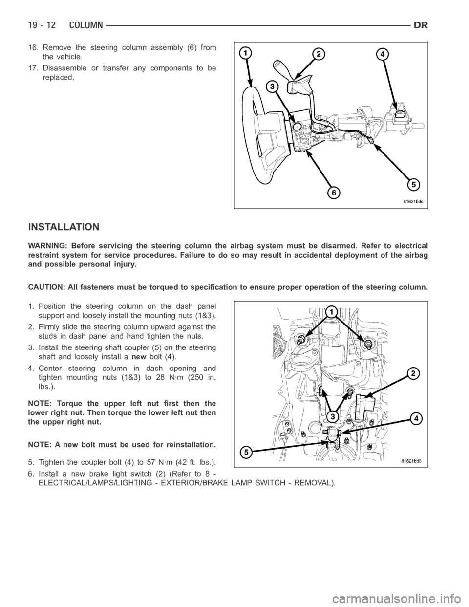
16. Remove the steering column assembly (6) from
the vehicle.
17. Disassemble or transfer any components to be
replaced.
INSTALLATION
WARNING: Before servicing the steering column the airbag system must be disarmed. Refer to electrical
restraint system for service procedures. Failure to do so may result in accidental deployment of the airbag
and possible personal injury.
CAUTION: All fasteners must be torqued to specification to ensure proper operation of the steering column.
1. Position the steering column on the dash panel
support and loosely install the mounting nuts (1&3).
2. Firmly slide the steering column upward against the
studs in dash panel and hand tighten the nuts.
3. Install the steering shaft coupler (5) on the steering
shaft and loosely install anewbolt (4).
4. Center steering column in dash opening and
tighten mounting nuts (1&3) to 28 Nꞏm (250 in.
lbs.).
NOTE: Torque the upper left nut first then the
lower right nut. Then torque the lower left nut then
the upper right nut.
NOTE: A new bolt must be used for reinstallation.
5. Tighten the coupler bolt (4) to 57 Nꞏm (42 ft. lbs.).
6. Install a new brake light switch (2) (Refer to 8 -
ELECTRICAL/LAMPS/LIGHTING - EXTERIOR/BRAKE LAMP SWITCH - REMOVAL).
Page 2745 of 5267
4.TRS SENSE CIRCUIT SHORT TO GROUND
Measure the resistance between ground and the identified (T1, T3, T41, or T42) TRS Sense circuit.
Is the resistance below 5.0 ohms?
Ye s>>
Repair the identified (T1, T3, T41, or T42) TRS Sense circuit for a short to ground.
Perform the PRNDL Fault Clearing Procedure – Go To 7
No>>
Go To 5
5.TRS SENSE CIRCUIT SHORT TO OTHER CIRCUITS
Measure the resistance between the identified (T1, T3, T41, or T42) TRS Sense circuit and all other circuits in the
Transmission Solenoid/TRS Assembly harness connector.
Is the resistance below 100k ohms between the identified (T1, T3, T41, or T42) TRS Sense circuit and
any other circuit(s) in the Transmission Solenoid/TRS Assembly harness connector?
Ye s>>
Repair the identified (T1, T3, T41, or T42) TRS Sense circuit for a short to other circuit(s).
Perform the PRNDL Fault Clearing Procedure – Go To 7
No>>
Using the schematics as a guide, check the Powertrain Control Module (PCM)terminals for corrosion,
damage, or terminal push out. Pay particular attention to all power and ground circuits. If no problems
are found, replace the PCM per the Service Information. With the scan tool,perform QUICK LEARN.
Perform the PRNDL Fault Clearing Procedure – Go To 7
6.INTERMITTENT WIRING AND CONNECTORS
The conditions necessary to set the DTC are not present at this time.
Using the schematics as a guide, inspect the wiring and connectors specifictothiscircuit.
Wiggle the wiring and connectors while checking for shorted and open circuits.
With the scan tool, check the DTC EVENT DATA to help identify the conditionsin which the DTC was set.
Were there any problems found?
Ye s>>
Repair as necessary.
Perform the PRNDL Fault Clearing Procedure – Go To 7
No>>
Te s t C o m p l e t e .
7.PRNDL FAULT CLEARING PROCEDURE
With the scan tool, erase Transmission DTCs.
Cycle the ignition off, then start the vehicle.
Firmly apply the brakes and shift into Overdrive.
NOTE: Vehicle must remain in Overdrive for at least 3.0 seconds.
With the brakes firmly applied, shift slowly through all gears (PRNDL) as least three times, pausing momentarily in
each gear.
NOTE: If all the PRNDL lights box individually then the error was cleared.
Shift into park and turn the ignition off to the lock position.
Ignition on, engine not running.
With the scan tool, read Transmission DTCs.
Does the DTC P0706 reset, or do all the PRNDL indicators remain boxed in parkor neutral?
Ye s>>
Return to the symptom list and perform diagnostics for P0706-TRANSMISSION RANGE SENSOR
RATIONALITY.
Go To 1
No>>
Te s t C o m p l e t e .
Perform 42RLE TRANSMISSION VERIFICATION TEST - VER 1. (Refer to 21 - TRANSMISSION/
TRANSAXLE/AUTOMATIC - 42RLE - STANDARD PROCEDURE)
Page 3340 of 5267
3.L/R CLUTCH CIRCUIT LEAKS IN THE VALVE BODY
Turn the ignition off to the lock position.
Remove the transmission oil pan per the Service Information.
Remove the valve body per the service information.
Check condition of the L/R accumulator springs.
Look for possible leak paths into the L/R clutch hydraulics circuit withinthe valve body.
Were any problems found?
Ye s>>
Repair as necessary.
Perform 45RFE/545RFE TRANSMISSION VERIFICATION TEST - VER 1. (Refer to 21- TRANSMIS-
SION/TRANSAXLE/AUTOMATIC - 45RFE/545RFE - STANDARD PROCEDURE)
No>>
Go To 4
4.AIR CHECK L/R CLUTCH CIRCUITS
Perform an air check on the L/R Clutch circuit per the Service Information.
Watch and listen for L/R Clutch piston movement.
Does the L/R piston stroke and return properly?
Ye s>>
Replace the Transmission/TRS Solenoid Assembly per the service information. With the scan tool, per-
form Quick Learn.
Perform 45RFE/545RFE TRANSMISSION VERIFICATION TEST - VER 1. (Refer to 21- TRANSMIS-
SION/TRANSAXLE/AUTOMATIC - 45RFE/545RFE - STANDARD PROCEDURE)
No>>
Repair internal transmission as necessary. Pay attention to the components related to the L/R clutch. A
broken or weak L/R clutch return spring, Accumulator Spring, and/or dislocated snap ring could cause
this problem.
Perform 45RFE/545RFE TRANSMISSION VERIFICATION TEST - VER 1. (Refer to 21- TRANSMIS-
SION/TRANSAXLE/AUTOMATIC - 45RFE/545RFE - STANDARD PROCEDURE)
5.VERIFY PCM OPERATION
NOTE: The TRANS TEMP DEG must be at least 43° C or 110° F before performing thefollowing steps.
Perform eight learnable starts. A learnable start is defined as follows: Start engine. From a standstill, accelerate
lightly to 80 Kmh or 50 MPH, then brake lightly to a stop. Turn off engine.
With the scan tool, record the CL VOL INDEX (CVI) for all clutches
With the scan tool, perform a BATTERY DISCONNECT.
With the scan tool, read the CVI’s and compare them to the readings recordedbefore the BATTERY DISCONNECT.
Are any of the CVI’s less than 5 or different than before the BATTERY DISCONNECT?
Ye s>>
Using the schematics as a guide, check the Powertrain Control Module (PCM)terminals for corrosion,
damage, or terminal push out. Pay particular attention to all power and ground circuits. If no problems
are found, replace the PCM per the Service Information. With the scan tool,perform QUICK LEARN.
Perform 45RFE/545RFE TRANSMISSION VERIFICATION TEST - VER 1. (Refer to 21- TRANSMIS-
SION/TRANSAXLE/AUTOMATIC - 45RFE/545RFE - STANDARD PROCEDURE)
No>>
Te s t C o m p l e t e .
Page 3342 of 5267
3.2C CLUTCH CIRCUIT LEAKS IN THE VALVE BODY
Turn the ignition off to the lock position.
Remove the transmission oil pan per the Service Information.
Remove the valve body per the service information.
Check condition of the 2C accumulator springs.
Look for possible leak paths into the 2C clutch hydraulics circuit within the valve body.
Were any problems found?
Ye s>>
Repair as necessary.
Perform 45RFE/545RFE TRANSMISSION VERIFICATION TEST - VER 1. (Refer to 21- TRANSMIS-
SION/TRANSAXLE/AUTOMATIC - 45RFE/545RFE - STANDARD PROCEDURE)
No>>
Go To 4
4.AIR CHECK 2C CLUTCH CIRCUIT
Turn the ignition off to the lock position.
Perform an air check on the 2C Clutch circuit per the Service Information.
Watch and listen for 2C Clutch piston movement.
Dose the piston stroke and return properly?
Ye s>>
Replace the Transmission/TRS Solenoid Assembly per the service information. With the scan tool, per-
form Quick Learn.
Perform 45RFE/545RFE TRANSMISSION VERIFICATION TEST - VER 1. (Refer to 21- TRANSMIS-
SION/TRANSAXLE/AUTOMATIC - 45RFE/545RFE - STANDARD PROCEDURE)
No>>
Repair internal transmission as necessary. Pay attention to the componentsrelatedtothe2Cclutch.A
broken or dislodged 2C return spring, snap ring or broken 2C Accumulator Spring could cause this prob-
lem.
Perform 45RFE/545RFE TRANSMISSION VERIFICATION TEST - VER 1. (Refer to 21- TRANSMIS-
SION/TRANSAXLE/AUTOMATIC - 45RFE/545RFE - STANDARD PROCEDURE)
5.VERIFY PCM OPERATION
NOTE: The TRANS TEMP DEG must be at least 43° C or 110° F before performing thefollowing steps.
Perform eight learnable starts. A learnable start is defined as follows: Start engine. From a standstill, accelerate
lightly to 80 Kmh or 50 MPH, then brake lightly to a stop. Turn off engine.
With the scan tool, record the CL VOL INDEX (CVI) for all clutches
With the scan tool, perform a BATTERY DISCONNECT.
With the scan tool, read the CVI’s and compare them to the readings recordedbefore the BATTERY DISCONNECT.
Are any of the CVI’s less than 5 or different than before the BATTERY DISCONNECT?
Ye s>>
Using the schematics as a guide, check the Powertrain Control Module (PCM)terminals for corrosion,
damage, or terminal push out. Pay particular attention to all power and ground circuits. If no problems
are found, replace the PCM per the Service Information. With the scan tool,perform QUICK LEARN.
Perform 45RFE/545RFE TRANSMISSION VERIFICATION TEST - VER 1. (Refer to 21- TRANSMIS-
SION/TRANSAXLE/AUTOMATIC - 45RFE/545RFE - STANDARD PROCEDURE)
No>>
Te s t C o m p l e t e .