Page 677 of 5267

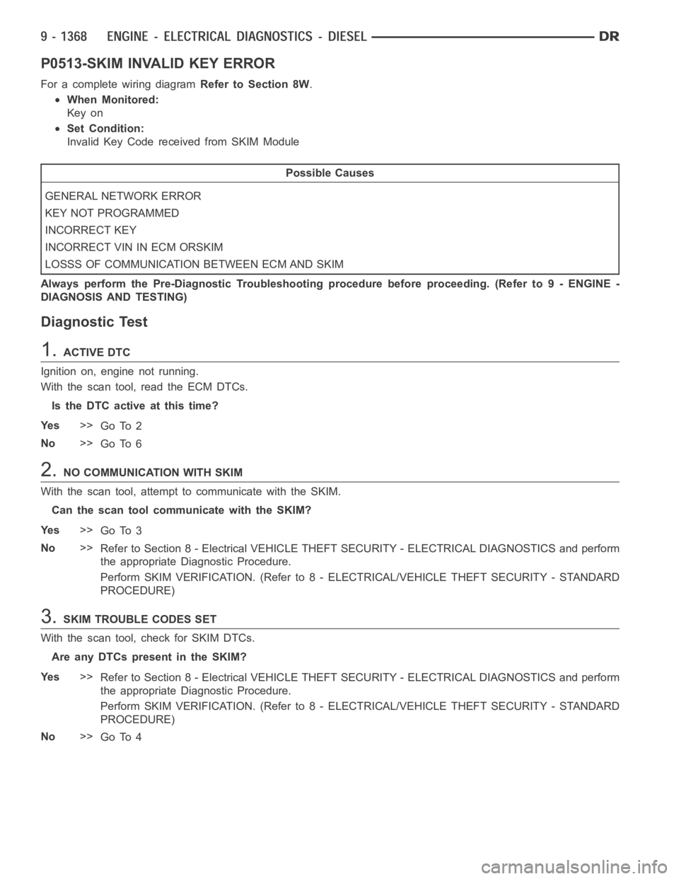
P0513-SKIM INVALID KEY ERROR
For a complete wiring diagramRefer to Section 8W.
When Monitored:
Key on
Set Condition:
Invalid Key Code received from SKIM Module
Possible Causes
GENERAL NETWORK ERROR
KEY NOT PROGRAMMED
INCORRECT KEY
INCORRECT VIN IN ECM ORSKIM
LOSSS OF COMMUNICATION BETWEEN ECM AND SKIM
Always perform the Pre-Diagnostic Troubleshooting procedure before proceeding. (Refer to 9 - ENGINE -
DIAGNOSIS AND TESTING)
Diagnostic Test
1.ACTIVE DTC
Ignition on, engine not running.
With the scan tool, read the ECM DTCs.
Is the DTC active at this time?
Ye s>>
Go To 2
No>>
Go To 6
2.NO COMMUNICATION WITH SKIM
With the scan tool, attempt to communicate with the SKIM.
Can the scan tool communicate with the SKIM?
Ye s>>
Go To 3
No>>
Refer to Section 8 - Electrical VEHICLE THEFT SECURITY - ELECTRICAL DIAGNOSTICS and perform
the appropriate Diagnostic Procedure.
Perform SKIM VERIFICATION. (Refer to 8 - ELECTRICAL/VEHICLE THEFT SECURITY - STANDARD
PROCEDURE)
3.SKIM TROUBLE CODES SET
With the scan tool, check for SKIM DTCs.
Are any DTCs present in the SKIM?
Ye s>>
Refer to Section 8 - Electrical VEHICLE THEFT SECURITY - ELECTRICAL DIAGNOSTICS and perform
the appropriate Diagnostic Procedure.
Perform SKIM VERIFICATION. (Refer to 8 - ELECTRICAL/VEHICLE THEFT SECURITY - STANDARD
PROCEDURE)
No>>
Go To 4
Page 678 of 5267

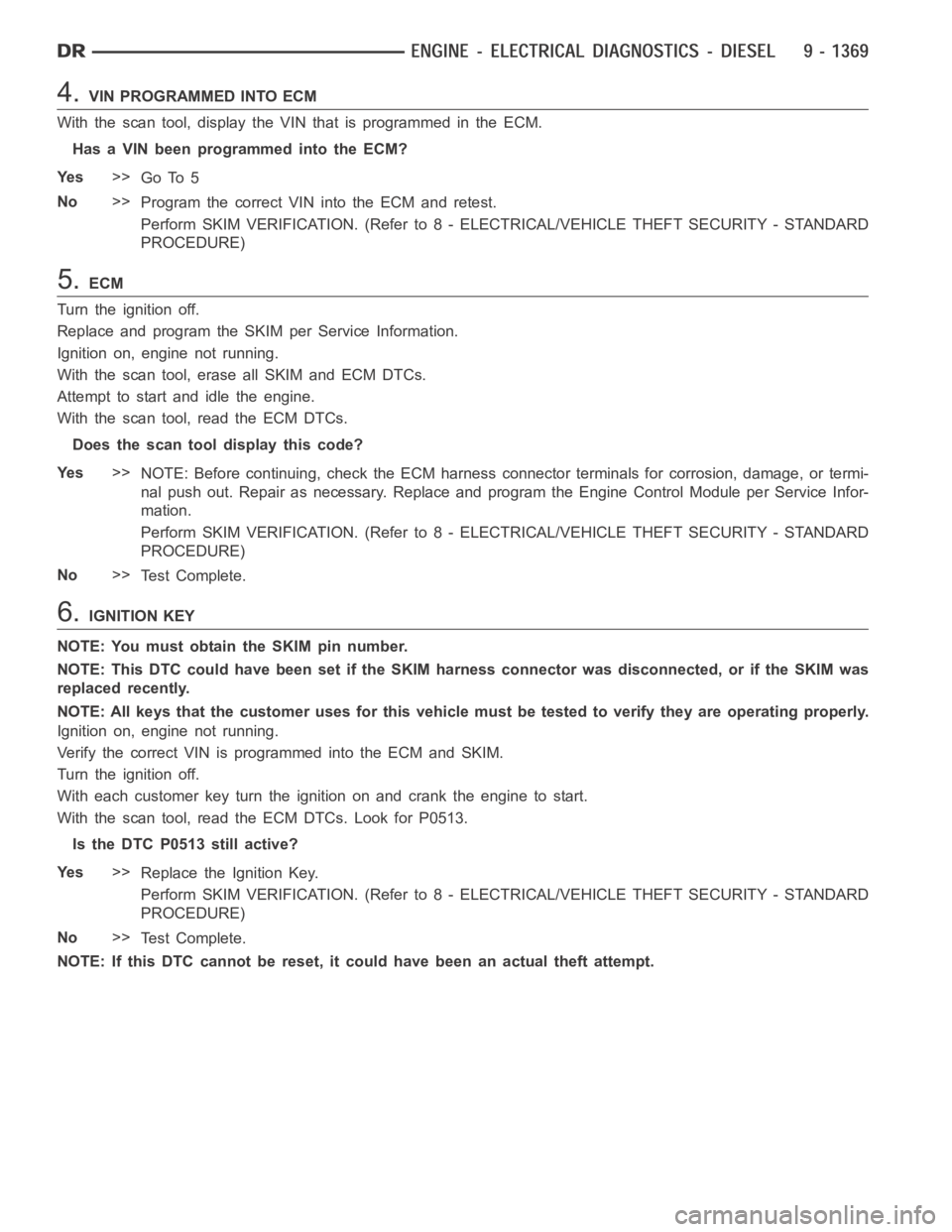
4.VIN PROGRAMMED INTO ECM
With the scan tool, display the VIN that is programmed in the ECM.
Has a VIN been programmed into the ECM?
Ye s>>
Go To 5
No>>
Program the correct VIN into the ECM and retest.
Perform SKIM VERIFICATION. (Refer to 8 - ELECTRICAL/VEHICLE THEFT SECURITY - STANDARD
PROCEDURE)
5.ECM
Turn the ignition off.
Replace and program the SKIM per Service Information.
Ignition on, engine not running.
With the scan tool, erase all SKIM and ECM DTCs.
Attempt to start and idle the engine.
With the scan tool, read the ECM DTCs.
Does the scan tool display this code?
Ye s>>
NOTE: Before continuing, check the ECM harness connector terminals for corrosion, damage, or termi-
nal push out. Repair as necessary. Replace and program the Engine Control Module per Service Infor-
mation.
Perform SKIM VERIFICATION. (Refer to 8 - ELECTRICAL/VEHICLE THEFT SECURITY - STANDARD
PROCEDURE)
No>>
Te s t C o m p l e t e .
6.IGNITION KEY
NOTE: You must obtain the SKIM pin number.
NOTE: This DTC could have been set if the SKIM harness connector was disconnected, or if the SKIM was
replaced recently.
NOTE: All keys that the customer uses for this vehicle must be tested to verify they are operating properly.
Ignition on, engine not running.
Verify the correct VIN is programmed into the ECM and SKIM.
Turn the ignition off.
With each customer key turn the ignition on and crank the engine to start.
With the scan tool, read the ECM DTCs. Look for P0513.
Is the DTC P0513 still active?
Ye s>>
Replace the Ignition Key.
Perform SKIM VERIFICATION. (Refer to 8 - ELECTRICAL/VEHICLE THEFT SECURITY - STANDARD
PROCEDURE)
No>>
Te s t C o m p l e t e .
NOTE: If this DTC cannot be reset, it could have been an actual theft attempt.
Page 897 of 5267

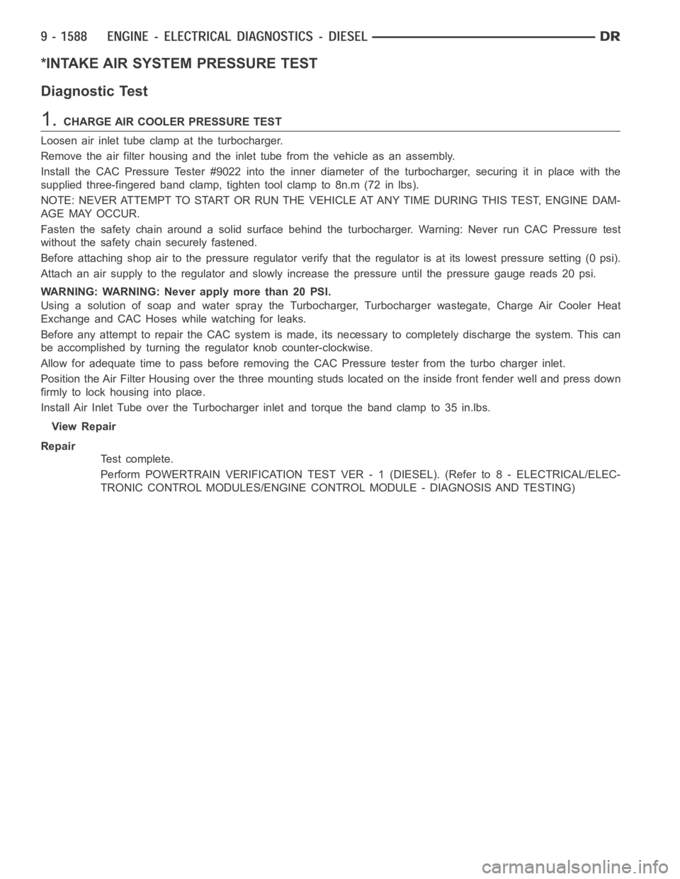
*INTAKE AIR SYSTEM PRESSURE TEST
Diagnostic Test
1.CHARGE AIR COOLER PRESSURE TEST
Loosen air inlet tube clamp at the turbocharger.
Remove the air filter housing and the inlet tube from the vehicle as an assembly.
Install the CAC Pressure Tester #9022 into the inner diameter of the turbocharger, securing it in place with the
supplied three-fingered band clamp, tighten tool clamp to 8n.m (72 in lbs).
NOTE: NEVER ATTEMPT TO START OR RUN THE VEHICLE AT ANY TIME DURING THIS TEST,ENGINE DAM-
AGE MAY OCCUR.
Fasten the safety chain around a solid surface behind the turbocharger. Warning: Never run CAC Pressure test
without the safety chain securely fastened.
Before attaching shop air to the pressure regulator verify that the regulator is at its lowest pressure setting (0 psi).
Attach an air supply to the regulator and slowly increase the pressure until the pressure gauge reads 20 psi.
WARNING: WARNING: Never apply more than 20 PSI.
Using a solution of soap and water spray the Turbocharger, Turbocharger wastegate, Charge Air Cooler Heat
Exchange and CAC Hoses while watching for leaks.
Before any attempt to repair the CAC system is made, its necessary to completely discharge the system. This can
be accomplished by turning the regulator knob counter-clockwise.
Allow for adequate time to pass before removing the CAC Pressure tester from the turbo charger inlet.
Position the Air Filter Housing over thethreemountingstudslocatedonthe inside front fender well and press down
firmly to lock housing into place.
Install Air Inlet Tube over the Turbocharger inlet and torque the band clampto35in.lbs.
View Repair
Repair
Te s t c o m p l e t e .
Perform POWERTRAIN VERIFICATION TEST VER - 1 (DIESEL). (Refer to 8 - ELECTRICAL/ELEC-
TRONIC CONTROL MODULES/ENGINE CONTROL MODULE - DIAGNOSIS AND TESTING)
Page 901 of 5267
When Monitored:
Ignition run time is greater than 1 second. Battery voltage between 9 and 16volts. Engine run time greater
than 3 seconds.
Set Condition:
The ECM doesn’t receive an ABS message over the CAN C circuit for 7 consecutive seconds. The circuit is
continuously monitored. One Trip fault.
Possible Causes
CAN C BUS OPEN OR SHORTED CONDITION
ABS MODULE
TIPM
PCM
Refer to 8 - ELECTRICAL/ELECTRONIC CONTROL MODULES - DIAGNOSIS AND TESTING for diagnostic
procedures and for further possible causes.
Diagnostic Test
1.ACTIVE DTC
Ignition on, engine not running.
With a scan tool, read ECM DTCs.
Is the DTC active at this time?
Ye s>>
Refer to 8 - ELECTRICAL/ELECTRONIC CONTROL MODULES - DIAGNOSIS AND TESTING for diag-
nostic procedures and for further possible causes.
No>>
Refer to the INTERMITTENT CONDITION Diagnostic Procedure.
Perform the POWERTRAIN VERIFICATION TEST. (Refer to 9 - ENGINE - STANDARD PROCEDURE)
Page 903 of 5267
When Monitored:
Ignition run time is greater than 1 second. Battery voltage between 9 and 16volts.
Set Condition:
TheECMdoesn’treceiveaFCM(TIPM)message over the CAN C circuit for 7 consecutive seconds. The
circuit is continuously monitored. One Trip fault.
Possible Causes
CAN C BUS OPEN OR SHORTED CONDITION
FCM (TIPM)
ECM
Refer to 8 - ELECTRICAL/ELECTRONIC CONTROL MODULES - DIAGNOSIS AND TESTING for diagnostic
procedures and for further possible causes.
Diagnostic Test
1.ACTIVE DTC
Ignition on, engine not running.
With a scan tool, read ECM DTCs.
Is the DTC active at this time?
Ye s>>
Refer to 8 - ELECTRICAL/ELECTRONIC CONTROL MODULES - DIAGNOSIS AND TESTING for diag-
nostic procedures and for further possible causes.
No>>
Refer to the INTERMITTENT CONDITION Diagnostic Procedure.
Perform the POWERTRAIN VERIFICATION TEST. (Refer to 9 - ENGINE - STANDARD PROCEDURE)
Page 905 of 5267

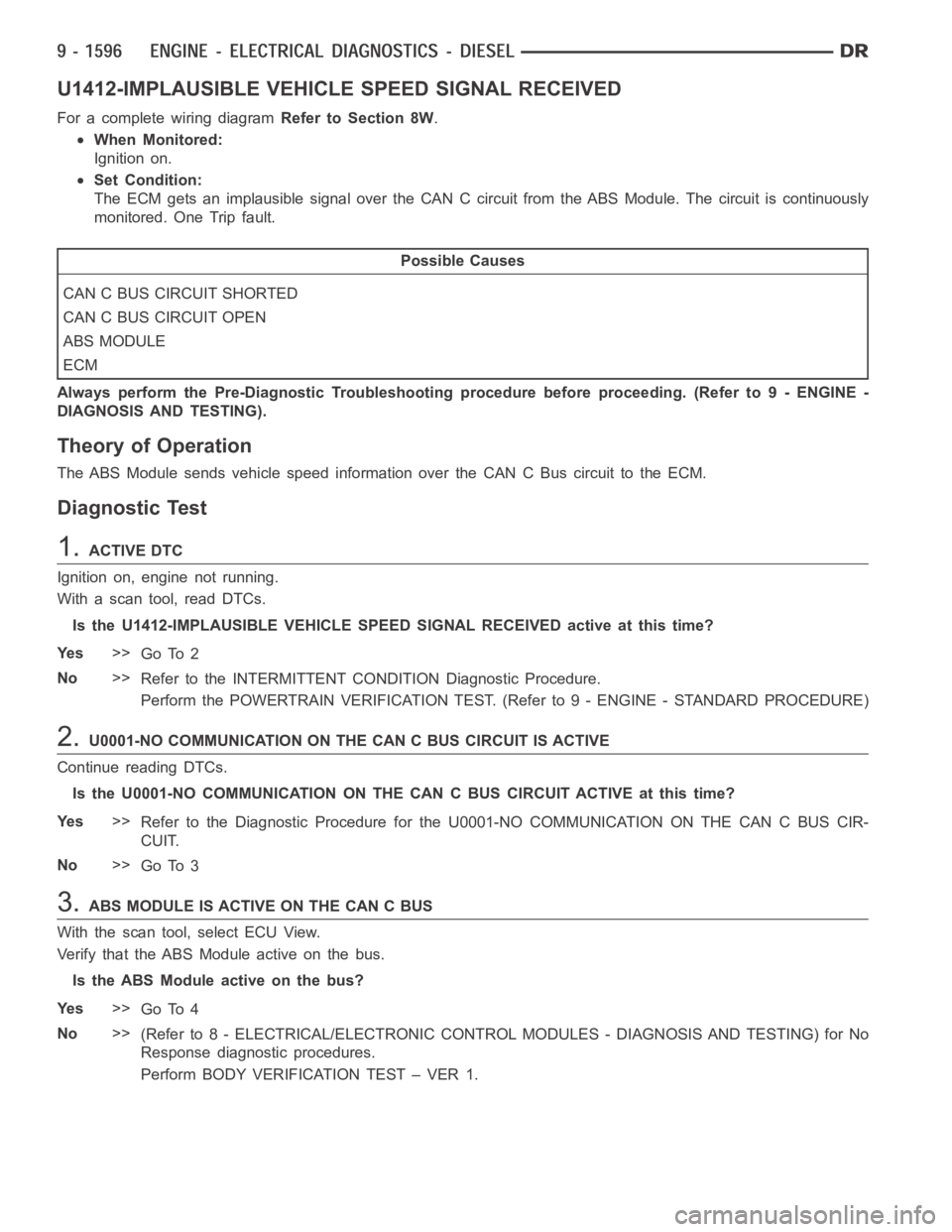
U1412-IMPLAUSIBLE VEHICLE SPEED SIGNAL RECEIVED
For a complete wiring diagramRefer to Section 8W.
When Monitored:
Ignition on.
Set Condition:
The ECM gets an implausible signal over the CAN C circuit from the ABS Module. The circuit is continuously
monitored. One Trip fault.
Possible Causes
CAN C BUS CIRCUIT SHORTED
CAN C BUS CIRCUIT OPEN
ABS MODULE
ECM
Always perform the Pre-Diagnostic Troubleshooting procedure before proceeding. (Refer to 9 - ENGINE -
DIAGNOSIS AND TESTING).
Theory of Operation
The ABS Module sends vehicle speed information over the CAN C Bus circuit tothe ECM.
Diagnostic Test
1.ACTIVE DTC
Ignition on, engine not running.
With a scan tool, read DTCs.
Is the U1412-IMPLAUSIBLE VEHICLE SPEED SIGNAL RECEIVED active at this time?
Ye s>>
Go To 2
No>>
Refer to the INTERMITTENT CONDITION Diagnostic Procedure.
Perform the POWERTRAIN VERIFICATION TEST. (Refer to 9 - ENGINE - STANDARD PROCEDURE)
2.U0001-NO COMMUNICATION ON THE CAN C BUS CIRCUIT IS ACTIVE
Continue reading DTCs.
Is the U0001-NO COMMUNICATION ON THE CAN C BUS CIRCUIT ACTIVE at this time?
Ye s>>
Refer to the Diagnostic Procedure for the U0001-NO COMMUNICATION ON THE CANCBUSCIR-
CUIT.
No>>
Go To 3
3.ABS MODULE IS ACTIVE ON THE CAN C BUS
With the scan tool, select ECU View.
Verify that the ABS Module active on the bus.
Is the ABS Module active on the bus?
Ye s>>
Go To 4
No>>
(Refer to 8 - ELECTRICAL/ELECTRONIC CONTROL MODULES - DIAGNOSIS AND TESTING) for No
Response diagnostic procedures.
Perform BODY VERIFICATION TEST – VER 1.
Page 906 of 5267
4.ACTIVE DTCS IN THE FCM
With the scan tool, select ECU View and select FCM (TIPM).
With the scan tool, read active DTCs.
Is the U0001-NO COMMUNICATION ON THE CAN C BUS CIRCUIT ACTIVE in the FCM at this time?
Ye s>>
Replace the ABS Module per Service Information.
Perform the POWERTRAIN VERIFICATION TEST. (Refer to 9 - ENGINE - STANDARD PROCEDURE)
No>>
Replace and program the Powertrain Control Module per Service Information.
Perform the POWERTRAIN VERIFICATION TEST. (Refer to 9 - ENGINE - STANDARD PROCEDURE)
Page 907 of 5267
U0141-LOST COMMUNICATION WITH ECU
For a complete wiring diagramRefer to Section 8W.