2006 DODGE RAM SRT-10 light
[x] Cancel search: lightPage 1255 of 5267
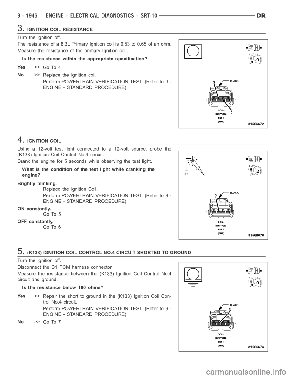
3.IGNITION COIL RESISTANCE
Turn the ignition off.
The resistance of a 8.3L Primary Ignition coil is 0.53 to 0.65 of an ohm.
Measure the resistance of the primary Ignition coil.
Is the resistance within the appropriate specification?
Ye s>>
Go To 4
No>>
Replace the Ignition coil.
Perform POWERTRAIN VERIFICATION TEST. (Refer to 9 -
ENGINE - STANDARD PROCEDURE)
4.IGNITION COIL
Using a 12-volt test light connected to a 12-volt source, probe the
(K133) Ignition Coil Control No.4 circuit.
Crank the engine for 5 seconds while observing the test light.
What is the condition of the test light while cranking the
engine?
Brightly blinking.
Replace the Ignition Coil.
Perform POWERTRAIN VERIFICATION TEST. (Refer to 9 -
ENGINE - STANDARD PROCEDURE)
ON constantly.
Go To 5
OFF constantly.
Go To 6
5.(K133) IGNITION COIL CONTROL NO.4 CIRCUIT SHORTED TO GROUND
Turn the ignition off.
Disconnect the C1 PCM harness connector.
Measure the resistance between the (K133) Ignition Coil Control No.4
circuit and ground.
Istheresistancebelow100ohms?
Ye s>>
Repair the short to ground in the (K133) Ignition Coil Con-
trol No.4 circuit.
Perform POWERTRAIN VERIFICATION TEST. (Refer to 9 -
ENGINE - STANDARD PROCEDURE)
No>>
Go To 7
Page 1258 of 5267
When Monitored:
With battery voltage greater than 8 volts during engine cranking or greater than 12 volts with engine running,
engine rpm less than 2016, and none of the coils in dwell when checked.
Set Condition:
Peak current is not achieved with battery based dwell plus 1.5 ms of diagnostic offset. It takes less than 3
seconds during cranking or up to 6 seconds while running to set.
Possible Causes
(K343) ASD RELAY OUTPUT CIRCUIT
IGNITION COIL
(K134) IGNITION COIL CONTROL NO.5 CIRCUIT OPEN
(K134) IGNITION COIL CONTROL NO.5 CIRCUIT SHORTED TO GROUND
PCM
Always perform the Pre-Diagnostic Troubleshooting procedure before proceeding. (Refer to 9 - ENGINE -
DIAGNOSIS AND TESTING)
1.GOOD TRIP EQUAL TO ZERO
Ignition on, engine not running.
With the scan tool, read DTCs and record the related Freeze Frame data.
Is the Good Trip Counter displayed and equal to zero?
Ye s>>
Go To 2
No>>
Refer to the INTERMITTENT CONDTION Diagnostic Procedure.
Perform POWERTRAIN VERIFICATION TEST. (Refer to 9 - ENGINE - STANDARD PROCEDURE)
2.(K343) ASD RELAY OUTPUT CIRCUIT
Turn the Ignition off.
Disconnect the Ignition coil harness connector.
Ignition on, engine not running.
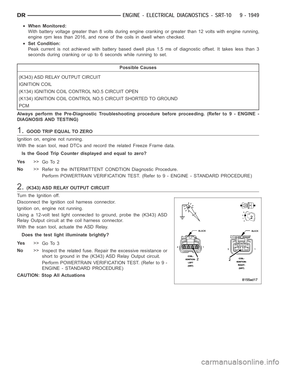
Using a 12-volt test light connected to ground, probe the (K343) ASD
Relay Output circuit at the coil harness connector.
With the scan tool, actuate the ASD Relay.
Does the test light illuminate brightly?
Ye s>>
Go To 3
No>>
Inspect the related fuse. Repair the excessive resistance or
short to ground in the (K343) ASD Relay Output circuit.
Perform POWERTRAIN VERIFICATION TEST. (Refer to 9 -
ENGINE - STANDARD PROCEDURE)
CAUTION: Stop All Actuations
Page 1259 of 5267
3.IGNITION COIL RESISTANCE
Turn the Ignition off.
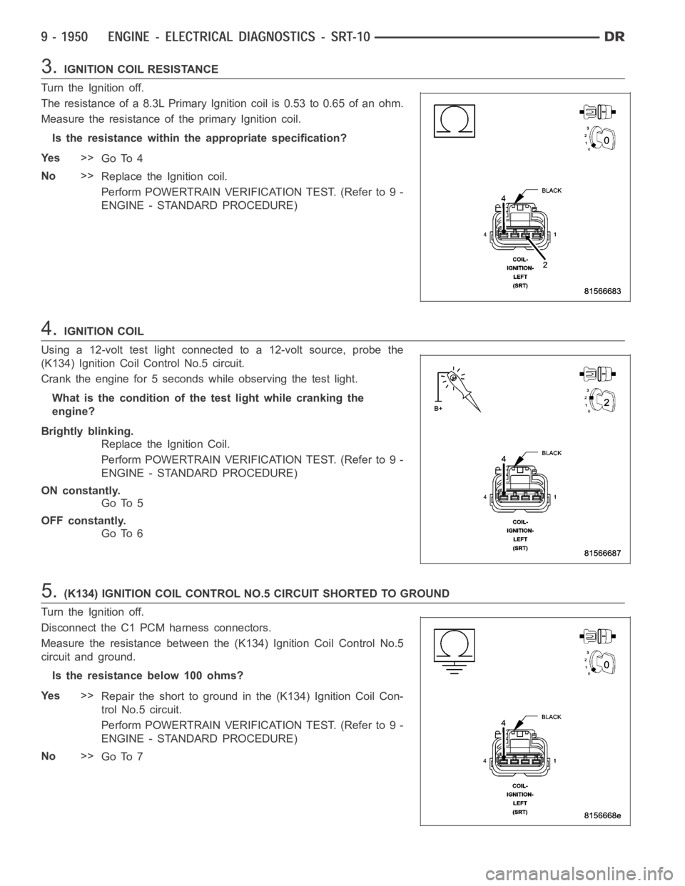
The resistance of a 8.3L Primary Ignition coil is 0.53 to 0.65 of an ohm.
Measure the resistance of the primary Ignition coil.
Is the resistance within the appropriate specification?
Ye s>>
Go To 4
No>>
Replace the Ignition coil.
Perform POWERTRAIN VERIFICATION TEST. (Refer to 9 -
ENGINE - STANDARD PROCEDURE)
4.IGNITION COIL
Using a 12-volt test light connected to a 12-volt source, probe the
(K134) Ignition Coil Control No.5 circuit.
Crank the engine for 5 seconds while observing the test light.
What is the condition of the test light while cranking the
engine?
Brightly blinking.
Replace the Ignition Coil.
Perform POWERTRAIN VERIFICATION TEST. (Refer to 9 -
ENGINE - STANDARD PROCEDURE)
ON constantly.
Go To 5
OFF constantly.
Go To 6
5.(K134) IGNITION COIL CONTROL NO.5 CIRCUIT SHORTED TO GROUND
Turn the Ignition off.
Disconnect the C1 PCM harness connectors.
Measure the resistance between the (K134) Ignition Coil Control No.5
circuit and ground.
Istheresistancebelow100ohms?
Ye s>>
Repair the short to ground in the (K134) Ignition Coil Con-
trol No.5 circuit.
Perform POWERTRAIN VERIFICATION TEST. (Refer to 9 -
ENGINE - STANDARD PROCEDURE)
No>>
Go To 7
Page 1274 of 5267
5.EVAPORATIVE EMISSION LEAK DETECTION
NOTE: A thorough visual inspection of the Evap system hoses, tubes, and connections may save time in
your diagnosis. Look for any physical damage or signs of wetness at connections. The strong smell of fuel
vapors may also aid diagnosis.
To continue testing, you will need Miller Tool #8404A Evaporative Emissions Leak Detector (EELD).
Remove the Air supply hose from the service port (if equipped) or from the #8404-ADP adapter.
Connect the SMOKE supply tip (black hose) to the service port (if equipped)or to the #8404-ADP adapter.
Set the smoke/air control switch to SMOKE.
NOTE: The flow meter indicator ball will not move in the smoke mode.
Press the remote smoke/air start button.
NOTE: Make sure that smoke has filled the EVAP system by continuing to presstheremotesmoke/airstart
button, remove the vehicle fuel cap, and wait for the smoke to exit. Once smoke is indicated reinstall the
fuel cap.
NOTE: For optimal performance, introduce smoke into the system for an additional 60 seconds; continue
introducing smoke at 15 second intervals, as necessary.
While still holding the remote smoke/air start button, use the white light(#8404-CLL) to follow the EVAP system
path, and look for the source of the leak indicated by exiting smoke.
If a leak is concealed from view (i.e., top of fuel tank), release the remotesmoke/air start button, and use the ultra-
violet (UV) black light #8404-UVL and the yellow goggles 8404-20 to look for residual traces of dye that is left
behind by the smoke.
The exiting smoke deposits a residual fluid that is either bright green or bright yellow in color when viewed with a
UV light.
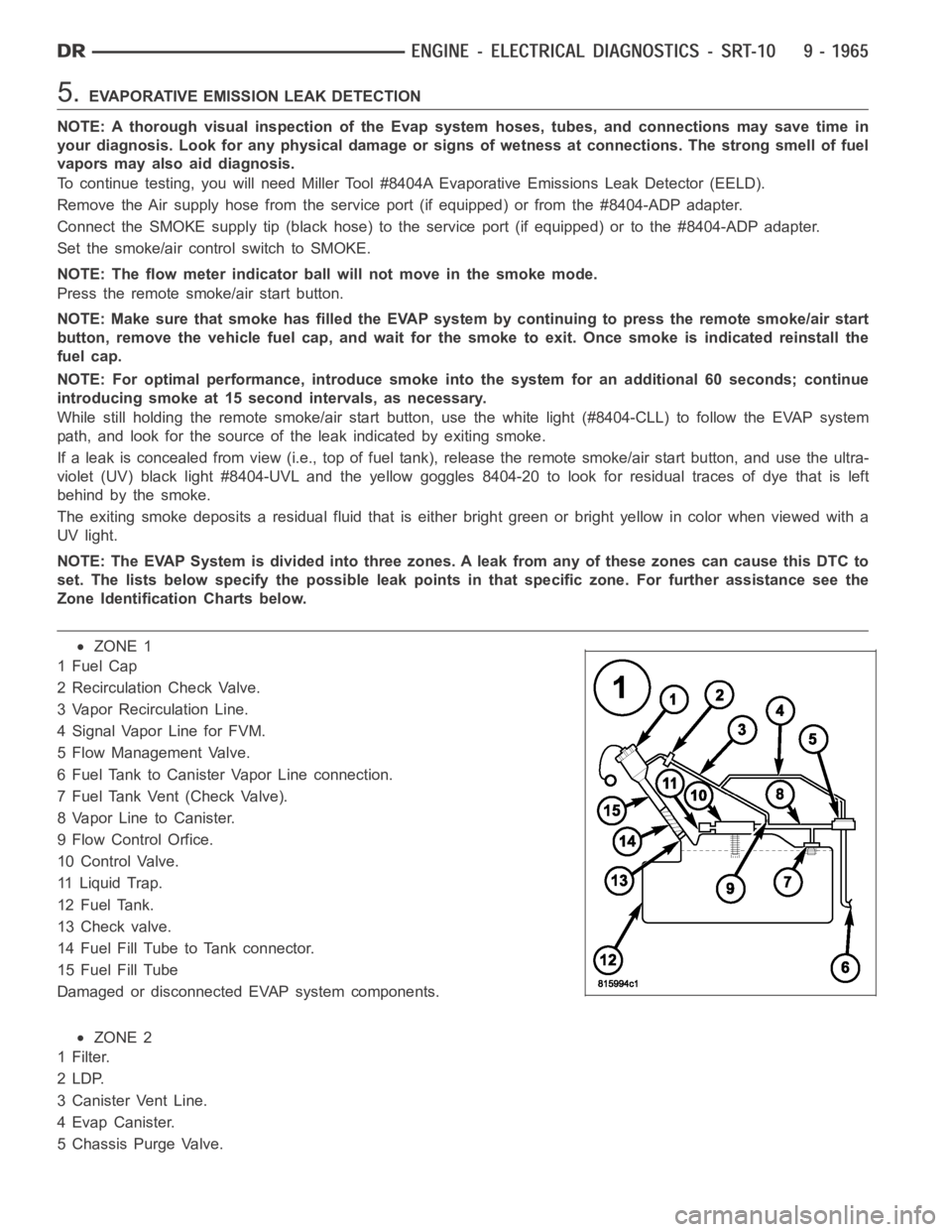
NOTE: The EVAP System is divided into three zones. A leak from any of these zonescancausethisDTCto
set. The lists below specify the possible leak points in that specific zone. For further assistance see the
Zone Identification Charts below.
ZONE 1
1FuelCap
2 Recirculation Check Valve.
3 Vapor Recirculation Line.
4 Signal Vapor Line for FVM.
5 Flow Management Valve.
6 Fuel Tank to Canister Vapor Line connection.
7 Fuel Tank Vent (Check Valve).
8 Vapor Line to Canister.
9 Flow Control Orfice.
10 Control Valve.
11 Liquid Trap.
12 Fuel Tank.
13 Check valve.
14 Fuel Fill Tube to Tank connector.
15 Fuel Fill Tube
Damaged or disconnected EVAP system components.
ZONE 2
1Filter.
2LDP.
3 Canister Vent Line.
4EvapCanister.
5 Chassis Purge Valve.
Page 1279 of 5267
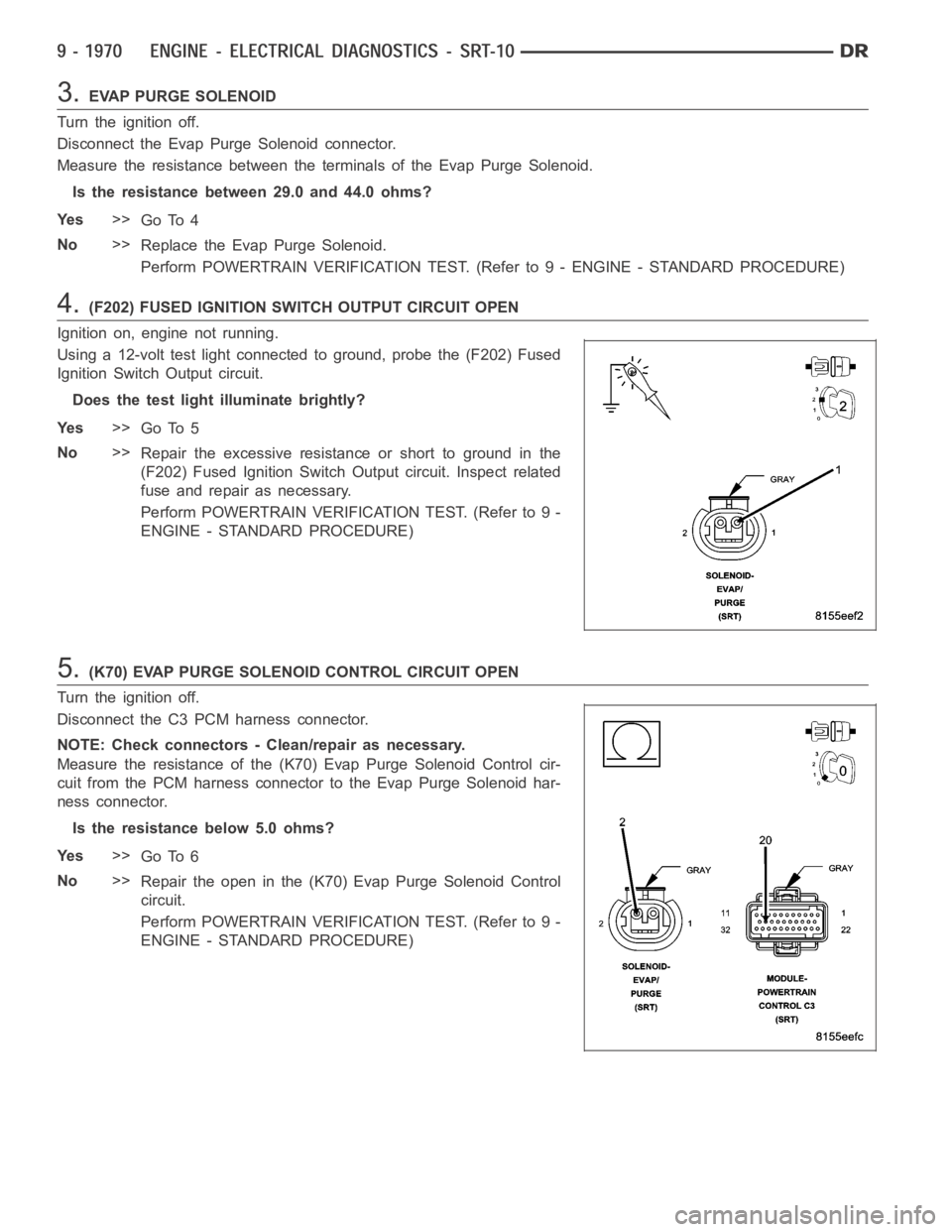
3.EVAP PURGE SOLENOID
Turn the ignition off.
Disconnect the Evap Purge Solenoid connector.
Measure the resistance between the terminals of the Evap Purge Solenoid.
Is the resistance between 29.0 and 44.0 ohms?
Ye s>>
Go To 4
No>>
Replace the Evap Purge Solenoid.
Perform POWERTRAIN VERIFICATION TEST. (Refer to 9 - ENGINE - STANDARD PROCEDURE)
4.(F202) FUSED IGNITION SWITCH OUTPUT CIRCUIT OPEN
Ignition on, engine not running.
Using a 12-volt test light connected to ground, probe the (F202) Fused
Ignition Switch Output circuit.
Does the test light illuminate brightly?
Ye s>>
Go To 5
No>>
Repair the excessive resistanceorshorttogroundinthe
(F202) Fused Ignition Switch Output circuit. Inspect related
fuse and repair as necessary.
Perform POWERTRAIN VERIFICATION TEST. (Refer to 9 -
ENGINE - STANDARD PROCEDURE)
5.(K70) EVAP PURGE SOLENOID CONTROL CIRCUIT OPEN
Turn the ignition off.
Disconnect the C3 PCM harness connector.
NOTE: Check connectors - Clean/repair as necessary.
Measure the resistance of the (K70) Evap Purge Solenoid Control cir-
cuit from the PCM harness connector to the Evap Purge Solenoid har-
ness connector.
Is the resistance below 5.0 ohms?
Ye s>>
Go To 6
No>>
Repair the open in the (K70) Evap Purge Solenoid Control
circuit.
Perform POWERTRAIN VERIFICATION TEST. (Refer to 9 -
ENGINE - STANDARD PROCEDURE)
Page 1284 of 5267
5.EVAPORATIVE EMISSION LEAK DETECTION
NOTE: A thorough visual inspection of the Evap system hoses, tubes, and connections may save time in
your diagnosis. Look for any physical damage or signs of wetness at connections. The strong smell of fuel
vapors may also aid diagnosis.
To continue testing, you will need Miller Tool #8404A Evaporative Emissions Leak Detector (EELD).
Remove the Air supply hose from the service port (if equipped) or from the #8404-ADP adapter.
Connect the SMOKE supply tip (black hose) to the service port (if equipped)or to the #8404-ADP adapter.
Set the smoke/air control switch to SMOKE.
NOTE: The flow meter indicator ball will not move in the smoke mode.
Press the remote smoke/air start button.
NOTE: Make sure that smoke has filled the EVAP system by continuing to presstheremotesmoke/airstart
button, remove the vehicle fuel cap, and wait for the smoke to exit. Once smoke is indicated reinstall the
fuel cap.
NOTE: For optimal performance, introduce smoke into the system for an additional 60 seconds; continue
introducing smoke at 15 second intervals, as necessary.
While still holding the remote smoke/air start button, use the white light(#8404-CLL) to follow the EVAP system
path, and look for the source of the leak indicated by exiting smoke.
If a leak is concealed from view (i.e., top of fuel tank), release the remotesmoke/air start button, and use the ultra-
violet (UV) black light #8404-UVL and the yellow goggles 8404-20 to look for residual traces of dye that is left
behind by the smoke.
The exiting smoke deposits a residual fluid that is either bright green or bright yellow in color when viewed with a
UV light.
NOTE: Carefully inspect the vent side of the EVAP Canister. Due to the filtering system in the canister the
smoke may not be as thick. Introducing smoke into the filtered side of the canister may assist in locating
the leak.
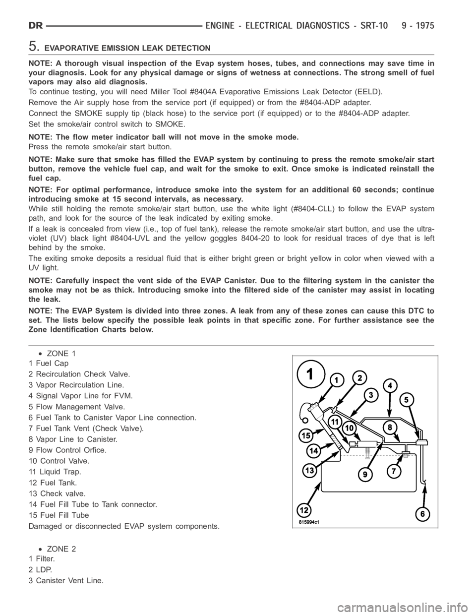
NOTE: The EVAP System is divided into three zones. A leak from any of these zonescancausethisDTCto
set. The lists below specify the possible leak points in that specific zone. For further assistance see the
Zone Identification Charts below.
ZONE 1
1FuelCap
2 Recirculation Check Valve.
3 Vapor Recirculation Line.
4 Signal Vapor Line for FVM.
5 Flow Management Valve.
6 Fuel Tank to Canister Vapor Line connection.
7 Fuel Tank Vent (Check Valve).
8 Vapor Line to Canister.
9 Flow Control Orfice.
10 Control Valve.
11 Liquid Trap.
12 Fuel Tank.
13 Check valve.
14 Fuel Fill Tube to Tank connector.
15 Fuel Fill Tube
Damaged or disconnected EVAP system components.
ZONE 2
1Filter.
2LDP.
3 Canister Vent Line.
Page 1302 of 5267
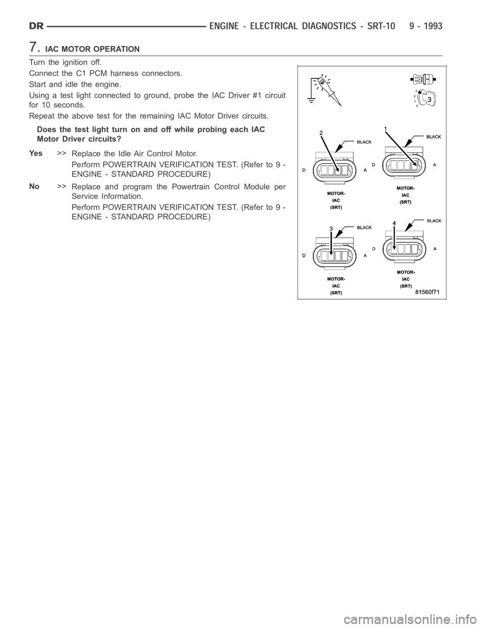
7.IAC MOTOR OPERATION
Turn the ignition off.
Connect the C1 PCM harness connectors.
Start and idle the engine.
Using a test light connected to ground, probe the IAC Driver #1 circuit
for 10 seconds.
Repeat the above test for the remaining IAC Motor Driver circuits.
Does the test light turn on and off while probing each IAC
MotorDrivercircuits?
Ye s>>
Replace the Idle Air Control Motor.
Perform POWERTRAIN VERIFICATION TEST. (Refer to 9 -
ENGINE - STANDARD PROCEDURE)
No>>
Replace and program the Powertrain Control Module per
Service Information.
Perform POWERTRAIN VERIFICATION TEST. (Refer to 9 -
ENGINE - STANDARD PROCEDURE)
Page 1310 of 5267
When Monitored:
With the ignition on and battery voltage above 10.4 volts.
Set Condition:
The oil pressure sensor signal at PCM goes above 4.9 volts. One Trip Fault.
Possible Causes
OIL PRESSURE SENSOR
(G6) OIL PRESSURE SIGNAL CIRCUIT SHORTED TO BATTERY VOLTAGE
(G6) OIL PRESSURE SIGNAL CIRCUIT OPEN
(K900) SENSOR GROUND CIRCUIT OPEN
PCM
Always perform the Pre-Diagnostic Troubleshooting procedure before proceeding. (Refer to 9 - ENGINE -
DIAGNOSIS AND TESTING)
1.OIL PRESSURE SENSOR VOLTAGE ABOVE 4.8 VOLTS
Ignition on, engine not running.
With the scan tool in Sensors, read the Oil Pressure Sensor voltage.
Is the Oil Pressure Sensor voltage above 4.8 volts?
Ye s>>
Go To 2
No>>
Refer to the INTERMITTENT CONDITION Diagnostic Procedure.
Perform POWERTRAIN VERIFICATION TEST. (Refer to 9 - ENGINE - STANDARD PROCEDURE)
2.OIL PRESSURE SENSOR
Turn the ignition off.
Disconnect the Oil Pressure Sensor harness connector.
Ignition on, engine not running.
Connect a jumper wire between the (G60) Oil Pressure Signal circuit and (K900) Sensor ground circuit at the Sen-
sor harness connector.
With the scan tool in Sensors, read the Oil Pressure Sensor voltage.
Is the voltage below 1.0 volt?
Ye s>>
Replace the Oil Pressure Sensor.
Perform POWERTRAIN VERIFICATION TEST. (Refer to 9 - ENGINE - STANDARD PROCEDURE)
No>>
Go To 3
NOTE: Remove the jumper wire before continuing.
3.(G6) OIL PRESSURE SIGNAL CIRCUIT SHORTED TO BATTERY VOLTAGE
Turn the ignition off.
Disconnect the PCM harness connectors.
Ignition on, engine not running.
Using a 12-volt test light connected to ground, probe the (G6) Oil PressureSignal circuit.
Is the test light brightly illuminated?
Ye s>>
Repair the short to voltage in the (G6) Oil Pressure Signal circuit.
Perform POWERTRAIN VERIFICATION TEST. (Refer to 9 - ENGINE - STANDARD PROCEDURE)
No>>
Go To 4