2006 DODGE RAM SRT-10 radiator cap
[x] Cancel search: radiator capPage 2040 of 5267
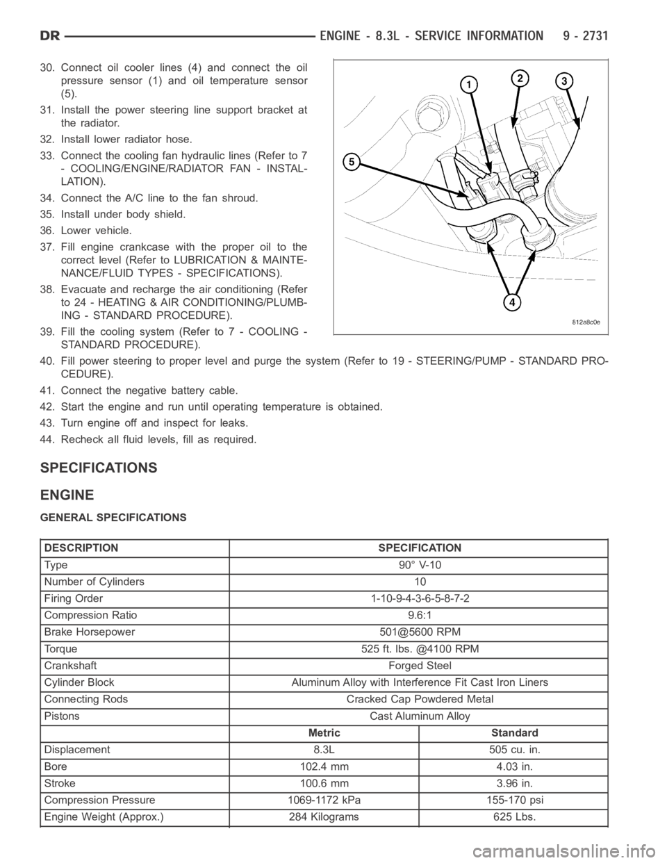
30. Connect oil cooler lines (4) and connect the oil
pressure sensor (1) and oil temperature sensor
(5).
31. Install the power steering line support bracket at
the radiator.
32. Install lower radiator hose.
33. Connect the cooling fan hydraulic lines (Refer to 7
- COOLING/ENGINE/RADIATOR FAN - INSTAL-
LATION).
34. Connect the A/C line to the fan shroud.
35. Install under body shield.
36. Lower vehicle.
37. Fill engine crankcase with the proper oil to the
correct level (Refer to LUBRICATION & MAINTE-
NANCE/FLUID TYPES - SPECIFICATIONS).
38. Evacuate and recharge the air conditioning (Refer
to 24 - HEATING & AIR CONDITIONING/PLUMB-
ING - STANDARD PROCEDURE).
39. Fill the cooling system (Refer to 7 - COOLING -
STANDARD PROCEDURE).
40. Fill power steering to proper leveland purge the system (Refer to 19 - STEERING/PUMP - STANDARD PRO-
CEDURE).
41. Connect the negative battery cable.
42. Start the engine and run until operating temperature is obtained.
43. Turn engine off and inspect for leaks.
44. Recheck all fluid levels, fill as required.
SPECIFICATIONS
ENGINE
GENERAL SPECIFICATIONS
DESCRIPTION SPECIFICATION
Ty pe 9 0° V-1 0
Number of Cylinders 10
Firing Order 1-10-9-4-3-6-5-8-7-2
Compression Ratio 9.6:1
Brake Horsepower 501@5600 RPM
Torque 525 ft. lbs. @4100 RPM
Crankshaft Forged Steel
Cylinder Block Aluminum Alloy with Interference Fit Cast Iron Liners
Connecting Rods Cracked Cap Powdered Metal
Pistons Cast Aluminum Alloy
Metric Standard
Displacement 8.3L 505 cu. in.
Bore 102.4 mm 4.03 in.
Stroke 100.6 mm 3.96 in.
Compression Pressure 1069-1172 kPa 155-170 psi
Engine Weight (Approx.) 284 Kilograms 625 Lbs.
Page 2078 of 5267
COVER-TIMING CHAIN
REMOVAL
1. Disconnect negative battery cable.
2. Disconnect throttle body air inlet duct at the throttle
body, CCV hose, disconnect the IAT sensor and
remove air cleaner housing cover (Refer to 9 -
ENGINE/AIR INTAKE SYSTEM - REMOVAL).
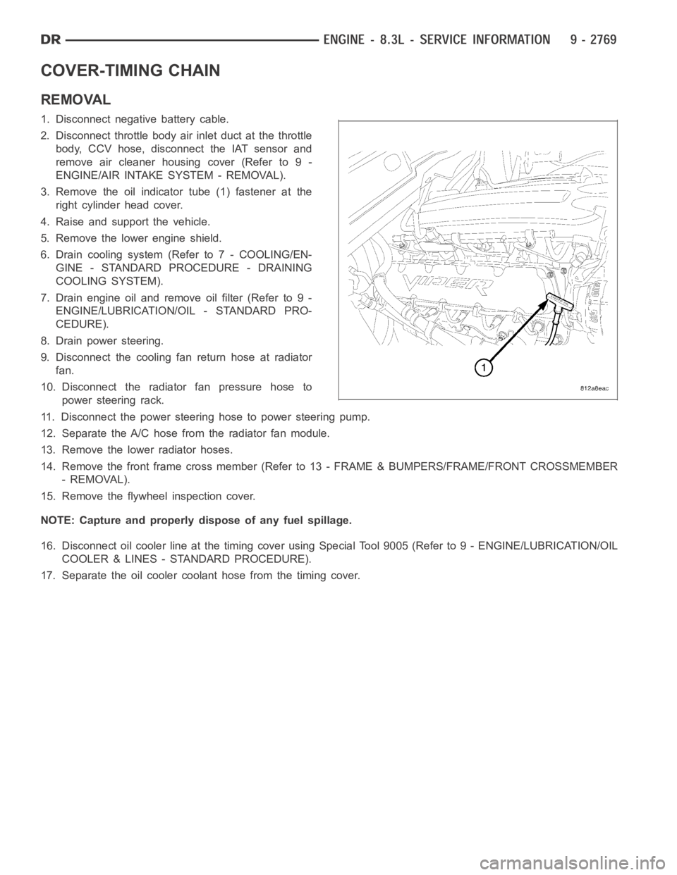
3. Remove the oil indicator tube (1) fastener at the
right cylinder head cover.
4. Raise and support the vehicle.
5. Remove the lower engine shield.
6. Drain cooling system (Refer to 7 - COOLING/EN-
GINE - STANDARD PROCEDURE - DRAINING
COOLING SYSTEM).
7. Drain engine oil and remove oil filter (Refer to 9 -
ENGINE/LUBRICATION/OIL - STANDARD PRO-
CEDURE).
8. Drain power steering.
9. Disconnect the cooling fan return hose at radiator
fan.
10. Disconnect the radiator fan pressure hose to
power steering rack.
11. Disconnect the power steering hose to power steering pump.
12. Separate the A/C hose from the radiator fan module.
13. Remove the lower radiator hoses.
14. Remove the front frame cross member (Refer to 13 - FRAME & BUMPERS/FRAME/FRONT CROSSMEMBER
- REMOVAL).
15. Remove the flywheel inspection cover.
NOTE: Capture and properly dispose of any fuel spillage.
16. Disconnect oil cooler line at the timing cover using Special Tool 9005 (Refer to 9 - ENGINE/LUBRICATION/OIL
COOLER & LINES - STANDARD PROCEDURE).
17. Separate the oil cooler coolant hose from the timing cover.
Page 3014 of 5267
FLUID AND FILTER
DIAGNOSIS AND TESTING
CAUSES OF BURNT FLUID
Burnt, discolored fluid is a result of overheating which has two primary causes.
1. A result of restricted fluid flow through the main and/or auxiliary cooler. This condition is usually the result of a
faulty or improperly installed drainback valve, a damaged oil cooler, or severe restrictions in the coolers and lines
caused by debris or kinked lines.
2. Heavy duty operation with a vehicle not properly equipped for this type of operation. Trailer towing or similar high
load operation will overheat the transmission fluid if the vehicle is improperly equipped. Such vehicles should
have an auxiliary transmission fluid cooler, a heavy duty cooling system,and the engine/axle ratio combination
needed to handle heavy loads.
EFFECTS OF INCORRECT FLUID LEVEL
Alowfluidlevelallowsthepumptotakeinairalongwiththefluid.Airinthe fluid will cause fluid pressures to be
low and develop slower than normal. If the transmission is overfilled, thegears churn the fluid into foam. This aer-
ates the fluid and causing the same conditions occurring with a low level. In either case, air bubbles cause fluid
overheating, oxidation, and varnish buildup which interferes with valveand clutch operation. Foaming also causes
fluid expansion which can result in fluid overflow from the transmission vent or fill tube. Fluid overflow can easily be
mistaken for a leak if inspection is not careful.
FLUID CONTAMINATION
Transmission fluid contamination is generally a result of:
adding incorrect fluid
failure to clean dipstick and fill tube when checking level
engine coolant entering the fluid
internal failure that generates debris
overheat that generates sludge (fluid breakdown)
failure to replace contaminated converter after repair
The use of non-recommended fluids can result in transmission failure. Theusual results are erratic shifts, slippage,
abnormal wear and eventual failure due to fluid breakdown and sludge formation. Avoid this condition by using rec-
ommended fluids only.
The dipstick cap and fill tube should be wiped clean before checking fluid level. Dirt, grease and other foreign mate-
rial on the cap and tube could fall into the tube if not removed beforehand. Take the time to wipe the cap and tube
clean before withdrawing the dipstick.
Engine coolant in the transmission fluid is generally caused by a cooler malfunction. The only remedy is to replace
the radiator as the cooler in the radiator is not a serviceable part. If coolant has circulated through the transmission,
an overhaul is necessary.
The torque converter should also be replaced whenever a failure generatessludge and debris. This is necessary
because normal converter flushing procedures will not remove all contaminants.
STANDARD PROCEDURE
FLUID LEVEL CHECK
The transmission sump has a dipstick to check oil similar to most automatictransmissions. It is located on the left
side of the engine. Be sure to wipe all dirt from dipstick handle before removing.
The torque converter fills in both the PARK and NEUTRAL positions. Place the selector lever in PARK to be sure
that the fluid level check is accurate.The engine should be running at idle speed for at least one minute, with
the vehicle on level ground.At normal operating temperature (approximately 82° C or 180° F), the fluidlevel is
correct if it is in the HOT region (cross-hatched area) on the oil level indicator. The fluid level should be in COLD
region at 21° C (70° F) fluid temperature. Adjust fluid level as necessary.Use only Mopar
ATF+4, Automatic Trans-
mission Fluid.
Page 3430 of 5267
FLUID AND FILTER
DIAGNOSIS AND TESTING
EFFECTS OF INCORRECT FLUID LEVEL
Alowfluidlevelallowsthepumptotakeinairalongwiththefluid.Airinthe fluid will cause fluid pressures to be
low and develop slower than normal. If the transmission is overfilled, thegears churn the fluid into foam. This aer-
ates the fluid and causing the same conditions occurring with a low level. In either case, air bubbles cause fluid
overheating, oxidation, and varnish buildup which interferes with valveand clutch operation. Foaming also causes
fluid expansion which can result in fluid overflow from the transmission vent or fill tube. Fluid overflow can easily be
mistaken for a leak if inspection is not careful.
CAUSES OF BURNT FLUID
Burnt, discolored fluid is a result of overheating which has three primarycauses.
1. Internal clutch slippage, usually caused by low line pressure, inadequate clutch apply pressure, or clutch seal
failure.
2. A result of restricted fluid flow through the main and/or auxiliary cooler. This condition is usually the result of a
faulty or improperly installed drainback valve, a damaged oil cooler, or severe restrictions in the coolers and lines
caused by debris or kinked lines.
3. Heavy duty operation with a vehicle not properly equipped for this type of operation. Trailer towing or similar high
load operation will overheat the transmission fluid if the vehicle is improperly equipped. Such vehicles should
have an auxiliary transmission fluid cooler, a heavy duty cooling system,and the engine/axle ratio combination
needed to handle heavy loads.
FLUID CONTAMINATION
Transmission fluid contamination is generally a result of:
adding incorrect fluid
failure to clean dipstick and fill tube when checking level
engine coolant entering the fluid
internal failure that generates debris
overheat that generates sludge (fluid breakdown)
failure to replace contaminated converter after repair
The use of non-recommended fluids can result in transmission failure. Theusual results are erratic shifts, slippage,
abnormal wear and eventual failure due to fluid breakdown and sludge formation. Avoid this condition by using rec-
ommended fluids only.
The dipstick cap and fill tube should be wiped clean before checking fluid level. Dirt, grease and other foreign mate-
rial on the cap and tube could fall into the tube if not removed beforehand. Take the time to wipe the cap and tube
clean before withdrawing the dipstick.
Engine coolant in the transmission fluid is generally caused by a cooler malfunction. The only remedy is to replace
the radiator as the cooler in the radiator is not a serviceable part. If coolant has circulated through the transmission,
an overhaul is necessary.
The torque converter should also be replaced whenever a failure generatessludge and debris. This is necessary
because normal converter flushing procedures will not remove all contaminants.
STANDARD PROCEDURE
FLUID LEVEL CHECK
Low fluid level can cause a variety of conditions because it allows the pumpto take in air along with the fluid. As
in any hydraulic system, air bubbles make the fluid spongy, therefore, pressures will be low and build up slowly.
Improper filling can also raise the fluid level too high. When the transmssion has too much fluid, the geartrain
churns up foam and cause the same conditions which occur with a low fluid level.
Page 3874 of 5267
FLUID AND FILTER
DIAGNOSIS AND TESTING
EFFECTS OF INCORRECT FLUID LEVEL
Alowfluidlevelallowsthepumptotakeinairalongwiththefluid.Airinthe fluid will cause fluid pressures to be
low and develop slower than normal. If the transmission is overfilled, thegears churn the fluid into foam. This aer-
ates the fluid and causing the same conditions occurring with a low level. In either case, air bubbles cause fluid
overheating, oxidation, and varnish buildup which interferes with valveand clutch operation. Foaming also causes
fluid expansion which can result in fluid overflow from the transmission vent or fill tube. Fluid overflow can easily be
mistaken for a leak if inspection is not careful.
CAUSES OF BURNT FLUID
Burnt, discolored fluid is a result of overheating which has two primary causes.
1. A result of restricted fluid flow through the main and/or auxiliary cooler. This condition is usually the result of a
faulty or improperly installed drainback valve, a damaged oil cooler, or severe restrictions in the coolers and lines
caused by debris or kinked lines.
2. Heavy duty operation with a vehicle not properly equipped for this type of operation. Trailer towing or similar high
load operation will overheat the transmission fluid if the vehicle is improperly equipped. Such vehicles should
have an auxiliary transmission fluid cooler, a heavy duty cooling system,and the engine/axle ratio combination
needed to handle heavy loads.
FLUID CONTAMINATION
Transmission fluid contamination is generally a result of:
adding incorrect fluid
failure to clean dipstick and fill tube when checking level
engine coolant entering the fluid
internal failure that generates debris
overheat that generates sludge (fluid breakdown)
failure to replace contaminated converter after repair
The use of non-recommended fluids can result in transmission failure. Theusual results are erratic shifts, slippage,
abnormal wear and eventual failure due to fluid breakdown and sludge formation. Avoid this condition by using rec-
ommended fluids only.
The dipstick cap and fill tube should be wiped clean before checking fluid level. Dirt, grease and other foreign mate-
rial on the cap and tube could fall into the tube if not removed beforehand. Take the time to wipe the cap and tube
clean before withdrawing the dipstick.
Engine coolant in the transmission fluid is generally caused by a cooler malfunction. The only remedy is to replace
the radiator as the cooler in the radiator is not a serviceable part. If coolant has circulated through the transmission,
an overhaul is necessary.
The torque converter should also be replaced whenever a failure generatessludge and debris. This is necessary
because normal converter flushing procedures will not remove all contaminants.
STANDARD PROCEDURE
FLUID LEVEL CHECK
Low fluid level can cause a variety of conditions because it allows the pumpto take in air along with the fluid. As
in any hydraulic system, air bubbles make the fluid spongy, therefore, pressures will be low and build up slowly.
Improper filling can also raise the fluid level too high. When the transmssion has too much fluid, the geartrain
churns up foam and cause the same conditions which occur with a low fluid level.
In either case, air bubbles can cause overheating and/or fluid oxidation,and varnishing. This can interfere with nor-
mal valve, clutch, and accumulator operation. Foaming can also result in fluid escaping from the transmission vent
where it may be mistaken for a leak.
Page 5050 of 5267
HVAC - SERVICE INFORMATION
DESCRIPTION
A manually controlled single zone type heating-air conditioning system or a manually controlleddualzonetypeheat-
ing-air conditioning system is available on this model.
To maintain the performance level of the heating, ventilation and air conditioning (HVAC) system, the engine cooling
system must be properly maintained. The use of a bug screen is not recommended. Any obstructions in front of the
radiator or A/C condenser will reduce the performance of the A/C and enginecooling systems.
The engine cooling system includes the radiator, thermostat, radiator hoses and the engine coolant pump. Refer to
7 - Cooling for more information before opening or attempting any service to the engine cooling system.
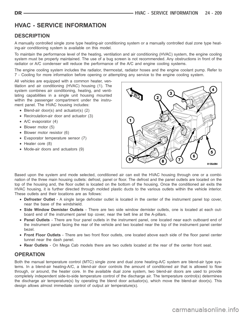
All vehicles are equipped with a common heater, ven-
tilation and air conditioning (HVAC) housing (1). The
system combines air conditioning, heating, and venti-
lating capabilities in a single unit housing mounted
within the passenger compartment under the instru-
ment panel. The HVAC housing includes:
Blend-air door(s) and actuator(s) (2)
Recirculation-air door and actuator (3)
A/C evaporator (4)
Blower motor (5)
Blower motor resistor (6)
Evaporator temperature sensor (7)
Heater core (8)
Mode-air doors and actuators (9)
Based upon the system and mode selected, conditioned air can exit the HVAC housing through one or a combi-
nation of the three main housing outlets: defrost, panel or floor. The defrost and the panel outlets are located on the
top of the housing and, the floor outlet is located on the bottom of the housing. Once the conditioned air exits the
HVAC housing, it is further directed through molded plastic ducts to the various outlets within the vehicle interior.
These outlets and their locations are as follows:
Defroster Outlet- A single large defroster outlet is located in the center of the instrumentpanel top cover,
near the base of the windshield.
Side Window Demister Outlets- There are two side window demister outlets, one is located at each out-
board end of the instrument panel top cover, near the belt line at the A-pillars.
Panel Outlets- There are four panel outlets in the instrument panel, one located near each outboard end of
the instrument panel facing the rear of the vehicle and two located near thetop of the instrument panel center
bezel.
Front Floor Outlets- There are two front floor outlets, one located above each side of the floorpanel center
tunnel near the dash panel.
Rear Outlets- On Mega Cab models there are two outlets located at the rear of the center front seat.
OPERATION
Both the manual temperature control (MTC) single zone and dual zone heating-A/C system are blend-air type sys-
tems. In a blend-air heating-A/C, a blend-air door controls the amount of conditioned air that is allowed to flow
through, or around, the heater core.In the available dual zone system, twoblend-air doors are used to provide
completely independent side-to-side temperature control of the discharge air. The temperature control(s) determines
the discharge air temperature(s) by operating the blend door actuator(s), which move the blend-air door(s). This
design allows almost immediate control of output air temperature(s).
Page 5128 of 5267
WARNING: The engine cooling system is designed to develop internal pressures up to 145 kilopascals (21
pounds per square inch). Do not remove or loosen the coolant pressure cap, cylinder block drain plugs,
radiator drain, radiator hoses, heater hoses, or hose clamps while the engine cooling system is hot and
under pressure. Allow the vehicle to cool for a minimum of 15 minutes beforeopening the cooling system
for service. Failure to observe this warning can result in serious burns from the heated engine coolant.
CAUTION
CAUTION: Never add R-12 to a refrigerant system designed to use R-134a. Do not use R-12 equipment or
parts on an R-134a A/C system. These refrigerants are not compatible and damage to the A/C system will
result.
CAUTION: Never use R-12 refrigerant oil in a A/C system designed to use R-134a refrigerant oil. These
refrigerant oils are not compatible and damage to the A/C system will result.
CAUTION: The use of A/C system sealers may result in damage to A/C refrigerant recovery/evacuation/re-
charging equipment and/or A/C system. Many federal, state/provincial and local regulations prohibit the
recharge of A/C systems with known leaks. DaimlerChrysler recommends thedetection of A/C system leaks
through the use of approved leak detectors and fluorescent leak detectiondyes. Vehicles found with A/C
system sealers should be treated as contaminated and replacement of the entire A/C refrigerant system is
recommended. A/C systems found to be contaminated with A/C system sealers, A/C stop-leak products or
seal conditioners voids the warranty for the A/C system.
CAUTION: Recover the refrigerant before opening any fitting or connection. Open the fittings with caution,
even after the system has been discharged. Never open or loosen a connection before recovering the refrig-
erant.
CAUTION: If equipped, do not remove the secondary retention clip from any spring-lock coupler connection
while the refrigerant system is under pressure. Recover the refrigerant before removing the secondary
retention clip. Open the fittings with caution, even after the system has been discharged. Never open or
loosen a connection before recovering the refrigerant.
CAUTION: The internal parts of the A/C system will remain stable as long as moisture-free refrigerant and
refrigerant oil is used. Abnormal amounts of dirt, moisture or air can upset the chemical stability. This may
cause operational troubles or even serious damage if present in more than very small quantities. Before
disconnecting a component, clean the outside of the fittings thoroughly to prevent contamination from
entering the refrigerant system. Keep service tools and the work area clean. Do not open the refrigerant
system or uncap a replacement component until you are ready to service the system. Immediately after
disconnecting a component from the refrigerant system, seal the open fittings with a cap or plug. This will
prevent contamination from entering the A/C system.
CAUTION: Refrigerant oil will absorb moisture from the atmosphere if leftuncapped. Do not open a con-
tainer of refrigerant oil until you are ready to use it. Replace the cap on the oil container immediately after
using. Store refrigerant oil only in a clean, airtight, and moisture-freecontainer.
CAUTION: Do not overcharge the refrigerant system. Overcharging will cause excessive compressor head
pressure and can cause compressor noise and A/C system failure.