Page 1866 of 5267

INSTALLATION
AUTOMATIC TRANSMISSION
CAUTION: The structural cover must be installed as described in the following steps. Failure to do so will
cause severe damage to the cover.
1. Position the structural cover in the vehicle.
2. Install all four bolts retaining the cover-to-engine. DO NOT tighten the bolts at this time.
3. Install the four cover-to-transmission bolts. Do NOT tighten at this time.
CAUTION: The structural cover must be held tightly against both the engineand the transmission bell hous-
ing during tightening sequence. Failure to do so may cause damage to the cover.
4. Torque the (4) structural dust cover bolts that go
intothetransmissionto6-11Nꞏm(50-100in.lbs.).
5. Torque the (4) structural dust cover bolts that go
into the engine block to 6-11 Nꞏm (50-100 in.lbs.).
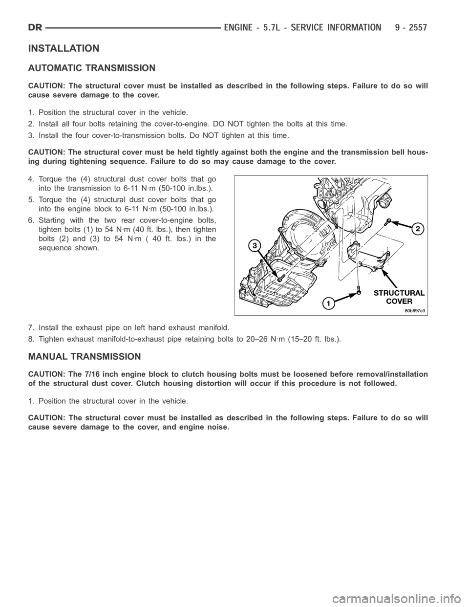
6. Starting with the two rearcover-to-engine bolts,
tighten bolts (1) to 54 Nꞏm (40 ft. lbs.), then tighten
bolts(2)and(3)to54Nꞏm(40ft.lbs.)inthe
sequence shown.
7. Install the exhaust pipe on left hand exhaust manifold.
8. Tighten exhaust manifold-to-exhaust pipe retaining bolts to 20–26 Nꞏm(15–20 ft. lbs.).
MANUAL TRANSMISSION
CAUTION: The 7/16 inch engine block to clutch housing bolts must be loosened before removal/installation
of the structural dust cover. Clutch housing distortion will occur if thisprocedure is not followed.
1. Position the structural cover in the vehicle.
CAUTION: The structural cover must be installed as described in the following steps. Failure to do so will
cause severe damage to the cover, and engine noise.
Page 1867 of 5267

2. Install all bolts retaining the cover-to-engine. DO
NOT tighten the bolts at this time.
3. Install the cover-to-transmission bolts. Do NOT
tighten at this time.
CAUTION: The structural cover must be held
tightly against the corner formed by the engine
and the transmission clutch housing during tight-
ening sequence. Failure to do so may cause dam-
age to the cover and engine noise.
4. Torque the (2) structural dust cover bolts that go
into the clutch housing to 6-11 Nꞏm (50-100 in.lbs.).
5. Torque the (4) structural dust cover bolts that go
into the engine block to 6-11 Nꞏm (50-100 in.lbs.).
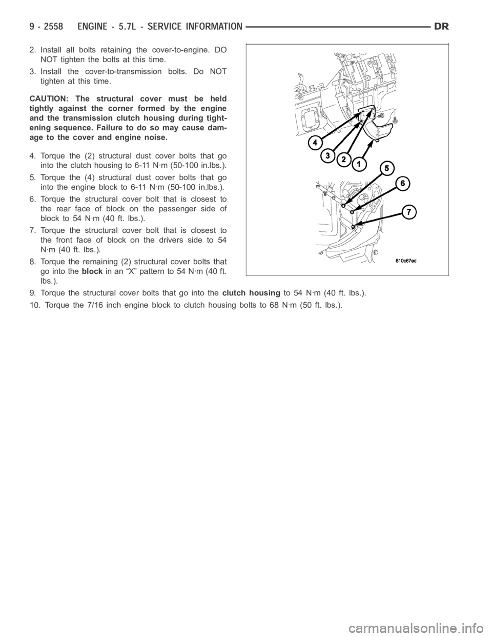
6. Torque the structural cover bolt that is closest to
the rear face of block on the passenger side of
blockto54Nꞏm(40ft.lbs.).
7. Torque the structural cover bolt that is closest to
the front face of block on the drivers side to 54
Nꞏm (40 ft. lbs.).
8. Torque the remaining (2) structural cover bolts that
go into theblockin an “X” pattern to 54 Nꞏm (40 ft.
lbs.).
9. Torque the structural cover bolts that go into theclutch housingto 54 Nꞏm (40 ft. lbs.).
10. Torque the 7/16 inch engine block to clutch housing bolts to 68 Nꞏm (50 ft.lbs.).
Page 1869 of 5267
REMOVAL
1. Disconnect the negative battery cable.
2. Remove the intake manifold. (Refer to 9 - ENGINE/MANIFOLDS/INTAKE MANIFOLD - REMOVAL).
3. Remove wiring harness connectors from the MDS solenoids.
4. Remove hold down bolt from MDS solenoid.
5. Remove MDS solenoid.
INSTALLATION
1. Verify that MDS bores are free of debris, before solenoid installation.
2. Install MDS solenoid fully into block.
3. Install hold down bolt and torque to 11 Nꞏm (97 in. lbs.).
4. Reconnect the MDS wiring harness to the solenoids.
5. Install the intake manifold. (Refer to 9 - ENGINE/MANIFOLDS/INTAKE MANIFOLD - INSTALLATION).
Page 1870 of 5267
MOUNT - FRONT
REMOVAL
2WD
1. Disconnect negative battery cable.
2. Raise vehicle.
3. Remove engine mount through bolts.
4. Raise engine using engine support fixture special
tool # 8534.
5. Remove engine mount to insulator bolts (1).
6. Remove insulator (2) from engine.
Page 1871 of 5267
4WD
1. Disconnect the negative cable from the battery.
2. Raise the vehicle.
3. Removetheskidplate.
4. Remove the front crossmember (Refer to 13 - FRAME & BUMPERS/FRAME/FRONTCROSSMEMBER -
REMOVAL).
5. Remove the engine oil filter.
6. Support the engine using engine support fixture, special tool # 8534.
7. Support the front axle with a suitable jack.
8. Remove the (4) bolts that attach the engine mounts to the front axle.
9. Remove the (3) bolts that attach the front axle to the left engine bracket.
10. Lower the front axle.
11. Remove the (6) through bolts
12. Raise the engine far enough to be able to remove the left (4) and right (8)engine mounts.
13. Remove the engine mounts (4,8).
Page 1872 of 5267
INSTALLATION
2WD
1. Install insulator (2) on the engine.
NOTE: For mount to engine block and left engine
bracket to front axle bolts, apply Mopar
Lock and
Seal Adhesive, Medium Strength Threadlocker.
2. Install upper and lower mount mounting bolts.
Tighten bolts to 61 Nꞏm (45 ft. lbs.).
3. Lower the engine using engine support fixture spe-
cial tool # 8534.
4. Install mount through bolts.
5. Tighten through bolts on both sides to 61 Nꞏm (45
ft. lbs.).
6. Lower vehicle.
7. Connect negative battery cable.
4WD
NOTE: For mount to engine block and left engine bracket to front axle bolts,apply MoparLock and Seal
Adhesive, Medium Strength Threadlocker.
1. Install the right (8) and left (4) side engine mounts to the front axle. Torque nuts to 94 Nꞏm (70 ft. lbs.).
2. Raise the front axle into the frame and install the left and right side through bolts. Torque nuts to 94 Nꞏm (70 ft.
lbs.).
Page 1873 of 5267
3. Insert the two upper through bolts into the right and left side engine mounts and loose assemble the two nuts
onto the through bolts.
4. Lower the engine using engine support fixture special tool # 8534, untilthe left and right side engine brackets
rest on the through bolts, and the lower engine bracket through holes alignwith the engine mounts, and the left
engine bracket holes align with the front axle slots.
5. Loose assemble the 3 bolts that attach the front axle to the left engine bracket.
6. Loose assemble the lower through bolts.
7. Torque the nuts for the 4 through bolts to 101 Nꞏm (75 ft. lbs.).
8. Torque the 3 bolts that attach the front axle to the left engine bracket to101Nꞏm(75ft.lbs.).
9. Install the engine oil filter, if removed.
10. Install the front crossmember (Refer to 13 - FRAME & BUMPERS/FRAME/FRONT CROSSMEMBER - INSTAL-
LATION).
11. Install the skid plate.
12. Lower the vehicle.
13. Reconnect the negative battery cable.
Page 1874 of 5267
MOUNT - REAR
REMOVAL
1. Raise the vehicle on a hoist.
2. Using a suitable jack, support transmission.
3. Remove the nuts from the transmission mount.
4. Remove the two bolts that attach the transmission
mount to the engine bracket.
5. Raise the transmission enough to remove the
mount from the crossmember.
6. Remove the mount.
INSTALLATION
NOTE: Threadlocking compound must be applied to the bolts before installation.
1. Install the two bolts that attach the transmission mount to the transmission bracket.
2. Torque the bolts to 61Nꞏm (45 ft.lbs.) torque.
3. Lower the transmission so the transmission mount rests on the crossmember, and the studs of the transmission
mount are aligned in the slots in the crossmember.
4. Install the nuts onto the transmission mount studs through the crossmember access slot.
5. Torque the nuts to 54Nꞏm (40 ft. lbs.).