2006 DODGE RAM SRT-10 fuel pump
[x] Cancel search: fuel pumpPage 1773 of 5267
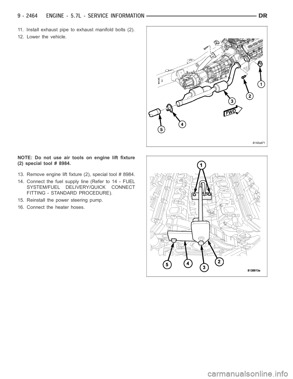
11. Install exhaust pipe to exhaust manifold bolts (2).
12. Lower the vehicle.
NOTE: Do not use air tools on engine lift fixture
(2) special tool # 8984.
13. Remove engine lift fixture (2), special tool # 8984.
14. Connect the fuel supply line (Refer to 14 - FUEL
SYSTEM/FUEL DELIVERY/QUICK CONNECT
FITTING - STANDARD PROCEDURE).
15. Reinstall the power steering pump.
16. Connect the heater hoses.
Page 1792 of 5267
1. Perform the Fuel System Pressure Release proce-
dure (Refer to 14 - FUEL SYSTEM/FUEL DELIV-
ERY - STANDARD PROCEDURE). Disconnect the
fuelsupplyline(Referto14-FUELSYSTEM/
FUEL DELIVERY/QUICK CONNECT FITTING -
STANDARD PROCEDURE).
2. Disconnect the battery negative cable.
3. Drain cooling system (Refer to 7 - COOLING -
STANDARD PROCEDURE).
4. Remove the air cleaner resonator and duct work
(Refer to 9 - ENGINE/AIR INTAKE SYSTEM -
REMOVAL).
5. Remove closed crankcase ventilation system.
6. Disconnect the exhaust at the exhaust manifolds.
7. Disconnect the evaporation control system.
8. Disconnect heater hoses.
9. Remove the power steering pump.
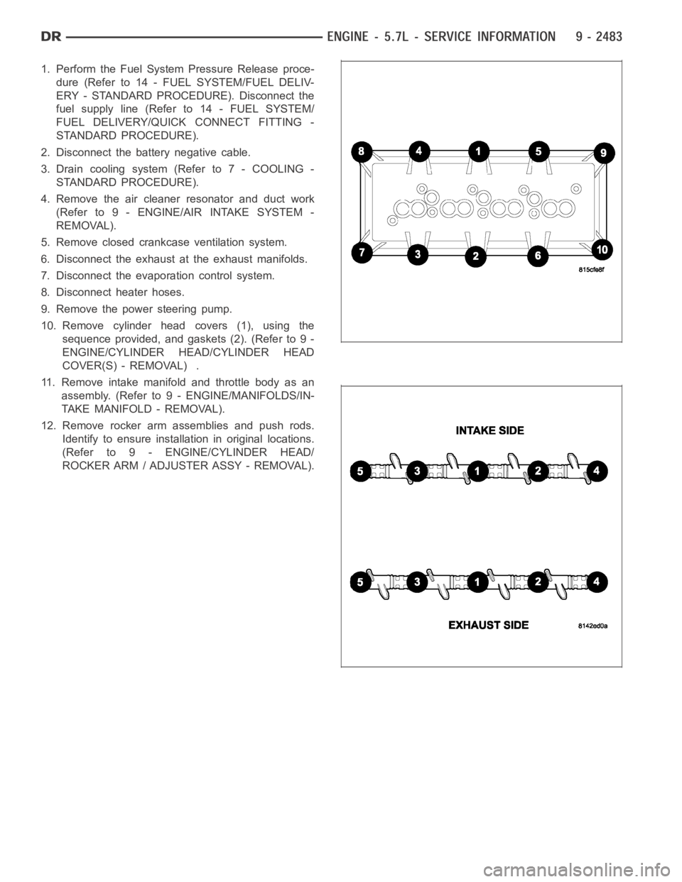
10. Remove cylinder head covers (1), using the
sequence provided, and gaskets (2). (Refer to 9 -
ENGINE/CYLINDER HEAD/CYLINDER HEAD
COVER(S) - REMOVAL) .
11. Remove intake manifold and throttle body as an
assembly. (Refer to 9 - ENGINE/MANIFOLDS/IN-
TAKE MANIFOLD - REMOVAL).
12. Remove rocker arm assemblies and push rods.
Identify to ensure installation in original locations.
(Refer to 9 - ENGINE/CYLINDER HEAD/
ROCKER ARM / ADJUSTER ASSY - REMOVAL).
Page 1796 of 5267
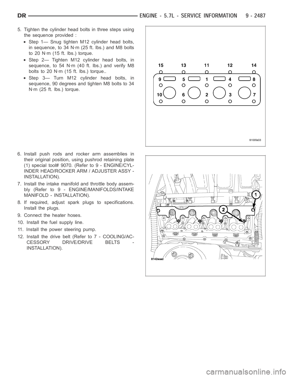
5. Tighten the cylinder head bolts in three steps using
the sequence provided :
Step 1— Snug tighten M12 cylinder head bolts,
in sequence, to 34 Nꞏm (25 ft. lbs.) and M8 bolts
to 20 Nꞏm (15 ft. lbs.) torque.
Step 2— Tighten M12 cylinder head bolts, in
sequence, to 54 Nꞏm (40 ft. lbs.) and verify M8
bolts to 20 Nꞏm (15 ft. lbs.) torque..
Step 3— Turn M12 cylinder head bolts, in
sequence, 90 degrees and tighten M8 bolts to 34
Nꞏm (25 ft. lbs.) torque.
6. Install push rods and rocker arm assemblies in
their original position, using pushrod retaining plate
(1) special tool# 9070. (Refer to 9 - ENGINE/CYL-
INDER HEAD/ROCKER ARM / ADJUSTER ASSY -
INSTALLATION).
7. Install the intake manifold and throttle body assem-
bly (Refer to 9 - ENGINE/MANIFOLDS/INTAKE
MANIFOLD - INSTALLATION).
8. If required, adjust spark plugs to specifications.
Install the plugs.
9. Connect the heater hoses.
10. Install the fuel supply line.
11. Install the power steering pump.
12. Install the drive belt (Refer to 7 - COOLING/AC-
CESSORY DRIVE/DRIVE BELTS -
INSTALLATION).
Page 1906 of 5267
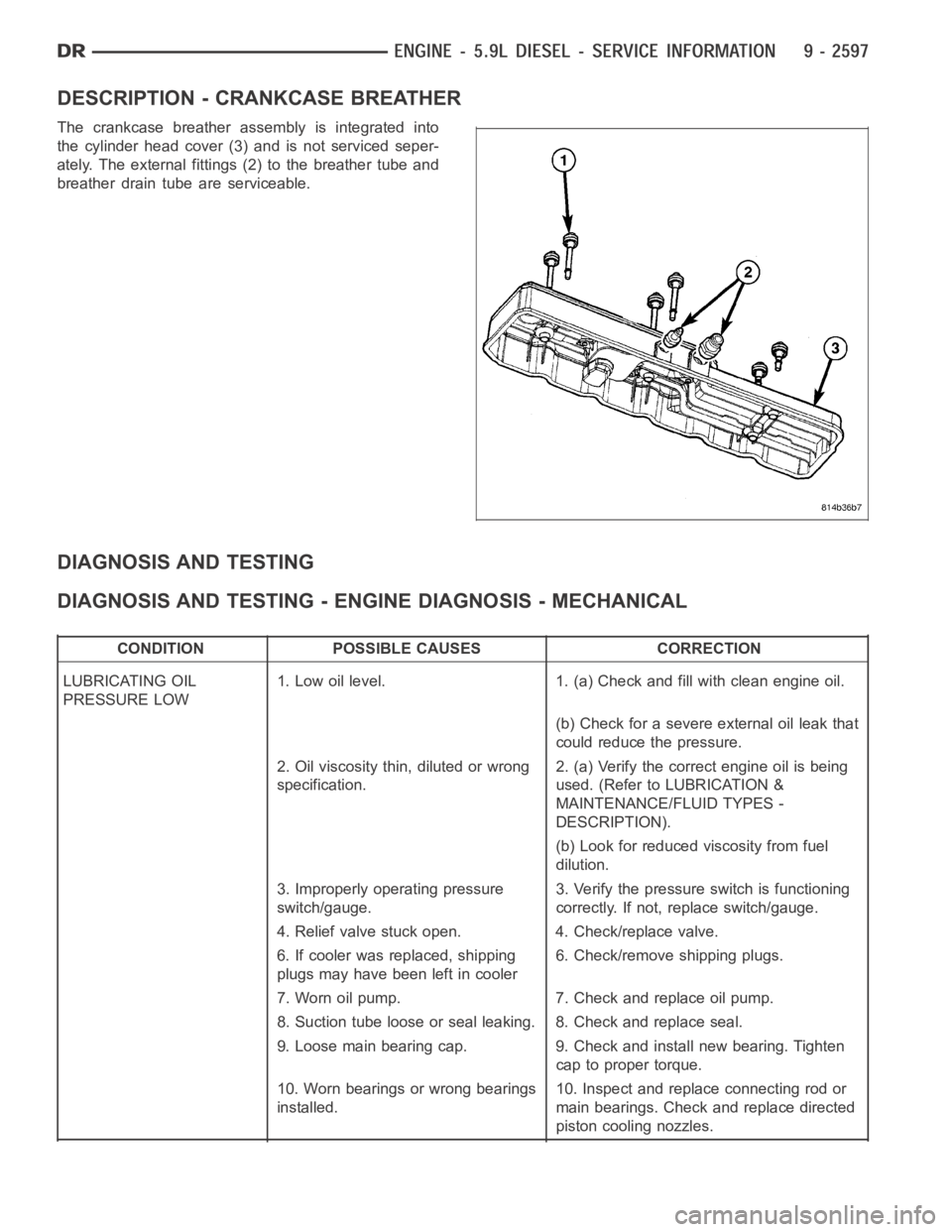
DESCRIPTION - CRANKCASE BREATHER
The crankcase breather assembly is integrated into
the cylinder head cover (3) and is not serviced seper-
ately. The external fittings (2) to the breather tube and
breather drain tube are serviceable.
DIAGNOSIS AND TESTING
DIAGNOSIS AND TESTING - ENGINE DIAGNOSIS - MECHANICAL
CONDITION POSSIBLE CAUSES CORRECTION
LUBRICATING OIL
PRESSURE LOW1. Low oil level. 1. (a) Check and fill with clean engine oil.
(b) Check for a severe external oil leak that
could reduce the pressure.
2. Oil viscosity thin, diluted or wrong
specification.2. (a) Verify the correct engine oil is being
used. (Refer to LUBRICATION &
MAINTENANCE/FLUID TYPES -
DESCRIPTION).
(b) Look for reduced viscosity from fuel
dilution.
3. Improperly operating pressure
switch/gauge.3. Verify the pressure switch is functioning
correctly. If not, replace switch/gauge.
4. Relief valve stuck open. 4. Check/replace valve.
6. If cooler was replaced, shipping
plugs may have been left in cooler6. Check/remove shipping plugs.
7. Worn oil pump. 7. Check and replace oil pump.
8. Suction tube loose or seal leaking. 8. Check and replace seal.
9. Loose main bearing cap. 9. Check and install new bearing. Tighten
cap to proper torque.
10. Worn bearings or wrong bearings
installed.10. Inspect and replace connecting rod or
main bearings. Check and replace directed
piston cooling nozzles.
Page 1909 of 5267
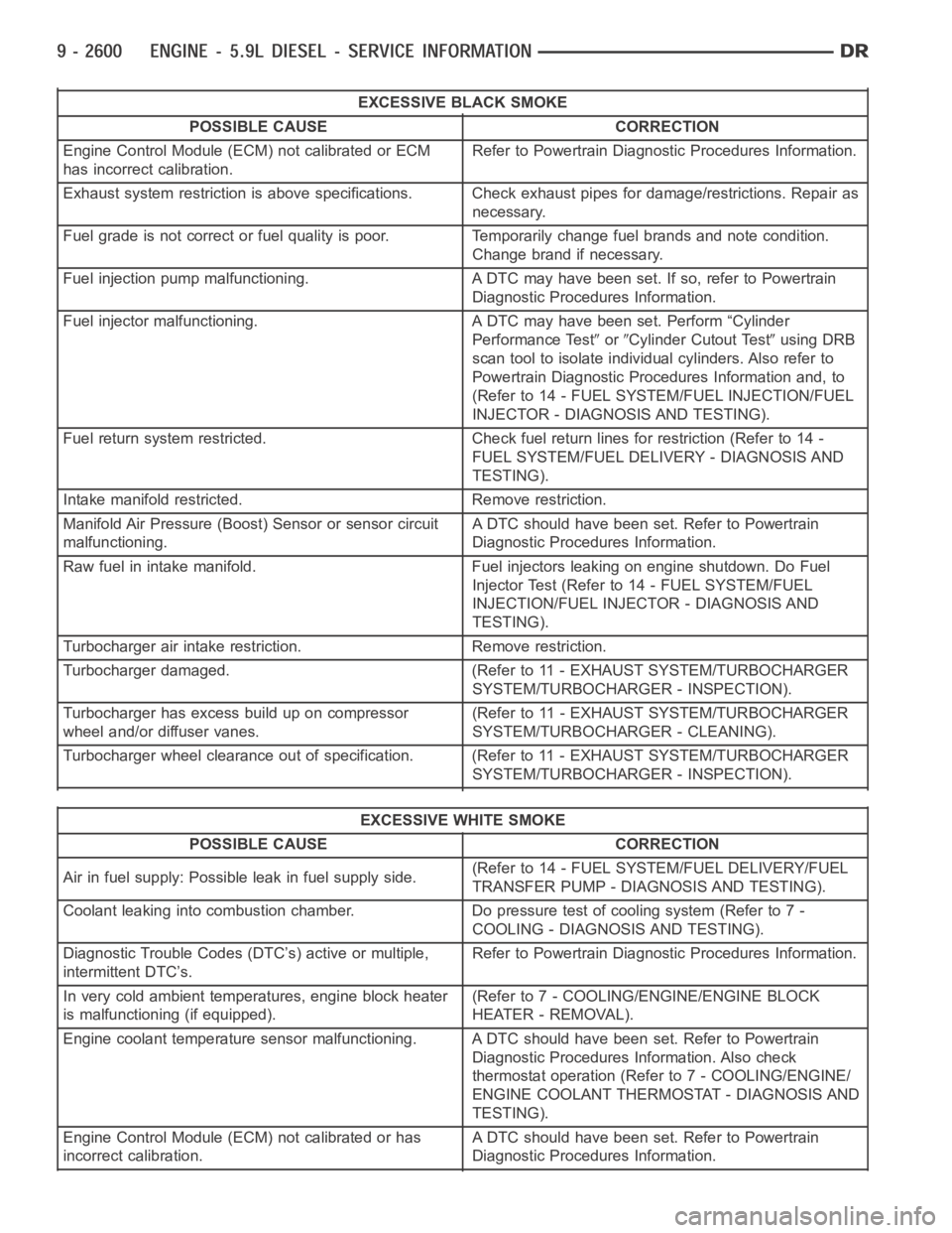
EXCESSIVE BLACK SMOKE
POSSIBLE CAUSE CORRECTION
Engine Control Module (ECM) not calibrated or ECM
has incorrect calibration.Refer to Powertrain Diagnostic Procedures Information.
Exhaust system restriction is above specifications. Check exhaust pipesfor damage/restrictions. Repair as
necessary.
Fuel grade is not correct or fuel quality is poor. Temporarily change fuel brands and note condition.
Change brand if necessary.
Fuel injection pump malfunctioning. A DTC may have been set. If so, refer toPowertrain
Diagnostic Procedures Information.
Fuel injector malfunctioning. A DTC may have been set. Perform “Cylinder
Performance Test
orCylinder Cutout Testusing DRB
scan tool to isolate individual cylinders. Also refer to
Powertrain Diagnostic Procedures Information and, to
(Refer to 14 - FUEL SYSTEM/FUEL INJECTION/FUEL
INJECTOR - DIAGNOSIS AND TESTING).
Fuel return system restricted. Check fuel return lines for restriction (Refer to 14 -
FUEL SYSTEM/FUEL DELIVERY - DIAGNOSIS AND
TESTING).
Intake manifold restricted. Remove restriction.
Manifold Air Pressure (Boost) Sensor or sensor circuit
malfunctioning.A DTC should have been set. Refer to Powertrain
Diagnostic Procedures Information.
Raw fuel in intake manifold. Fuel injectors leaking on engine shutdown. DoFuel
Injector Test (Refer to 14 - FUEL SYSTEM/FUEL
INJECTION/FUEL INJECTOR - DIAGNOSIS AND
TESTING).
Turbocharger air intake restriction. Remove restriction.
Turbocharger damaged. (Refer to 11 - EXHAUST SYSTEM/TURBOCHARGER
SYSTEM/TURBOCHARGER - INSPECTION).
Turbocharger has excess build up on compressor
wheel and/or diffuser vanes.(Refer to 11 - EXHAUST SYSTEM/TURBOCHARGER
SYSTEM/TURBOCHARGER - CLEANING).
Turbocharger wheel clearance out of specification. (Refer to 11 - EXHAUSTSYSTEM/TURBOCHARGER
SYSTEM/TURBOCHARGER - INSPECTION).
EXCESSIVE WHITE SMOKE
POSSIBLE CAUSE CORRECTION
Air in fuel supply: Possible leak in fuel supply side.(Refer to 14 - FUEL SYSTEM/FUEL DELIVERY/FUEL
TRANSFER PUMP - DIAGNOSIS AND TESTING).
Coolant leaking into combustion chamber. Do pressure test of cooling system (Refer to 7 -
COOLING - DIAGNOSIS AND TESTING).
Diagnostic Trouble Codes (DTC’s) active or multiple,
intermittent DTC’s.Refer to Powertrain Diagnostic Procedures Information.
In very cold ambient temperatures, engine block heater
is malfunctioning (if equipped).(Refer to 7 - COOLING/ENGINE/ENGINE BLOCK
HEATER - REMOVAL).
Engine coolant temperature sensor malfunctioning. A DTC should have beenset. Refer to Powertrain
Diagnostic Procedures Information. Also check
thermostat operation (Refer to 7 - COOLING/ENGINE/
ENGINE COOLANT THERMOSTAT - DIAGNOSIS AND
TESTING).
Engine Control Module (ECM) not calibrated or has
incorrect calibration.A DTC should have been set. Refer to Powertrain
Diagnostic Procedures Information.
Page 1910 of 5267

EXCESSIVE WHITE SMOKE
POSSIBLE CAUSE CORRECTION
Fuel filter plugged. Refer to Powertrain Diagnostic Manual for fuel system
testing.
Fuel grade not correct or fuel quality is poor. Temporarily change fuel brands and note condition.
Change brand if necessary.
Fuel heater element or fuel heater temperature sensor
malfunctioning. This will cause wax type build-up in fuel
filter.Refer to Fuel Heater Testing (Refer to 14 - FUEL
SYSTEM/FUEL DELIVERY/FUEL HEATER -
DIAGNOSIS AND TESTING).
Fuel injector malfunctioning. A DTC should have been set. Perform “Cylinder
Performance Test
orCylinder cutout Testusing DRB
scan tool to isolate individual cylinders. Also refer to
Powertrain Diagnostic Procedures Information and,
(Refer to 14 - FUEL SYSTEM/FUEL INJECTION/FUEL
INJECTOR - DIAGNOSIS AND TESTING).
Fuel injector hold-downs loose. Torque to specifications.
Fuel injector protrusion not correct. Check washer (shim) at bottom of fuel injector for
correct thickness. (Referto 14 - FUEL SYSTEM/FUEL
INJECTION/FUEL INJECTOR - INSTALLATION)
Fuel injection pump malfunctioning. A DTC should have been set. Refer to Powertrain
Diagnostic Procedures Information.
Fuel supply side restriction. Refer to Powertrain Diagnostic Manual for fuel system
testing.
Fuel transfer (lift) pump malfunctioning. A DTC may have been set. Refer toPowertrain
Diagnostic Procedures Information.
Intake/Exhaust valve adjustments not correct (too tight). (Refer to 9 - ENGINE/CYLINDER HEAD/INTAKE/
EXHAUST VALVES & SEATS - STANDARD
PROCEDURE).
Intake manifold air temperature sensor malfunctioning. A DTC should havebeen set. Refer to Powertrain
Diagnostic Procedures Information.
Intake manifold heater circuit not functioning correctly in
cold weather.A DTC should have been set. Refer to Powertrain
Diagnostic Procedures Information. Also check heater
elements for correct operation.
Intake manifold heater elements not functioning
correctly in cold weather.A DTC should have been set if heater elements are
malfunctioning. Refer to Powertrain Diagnostic
Procedures Information.
Internal engine damage (scuffed cylinder). Analyze engine oil and inspect oil filter to locate area of
probable damage.
Restriction in fuel supply side of fuel system. Refer to Powertrain Diagnostic Manual for fuel system
testing.
EXCESSIVE BLUE SMOKE
POSSIBLE CAUSE CORRECTION
Dirty air cleaner or restricted turbocharger intake duct. Check Filter Minder
at air filter housing. (Refer to 9 -
ENGINE/AIR INTAKE SYSTEM/AIR CLEANER
ELEMENT - REMOVAL).
Air leak in boost system between turbocharger
compressor outlet and intake manifold.Service air charge system..
Obstruction in exhaust manifold. Remove exhaust manifold and inspect forblockage
(Refer to 9 - ENGINE/MANIFOLDS/EXHAUST
MANIFOLD - REMOVAL).
Page 1911 of 5267
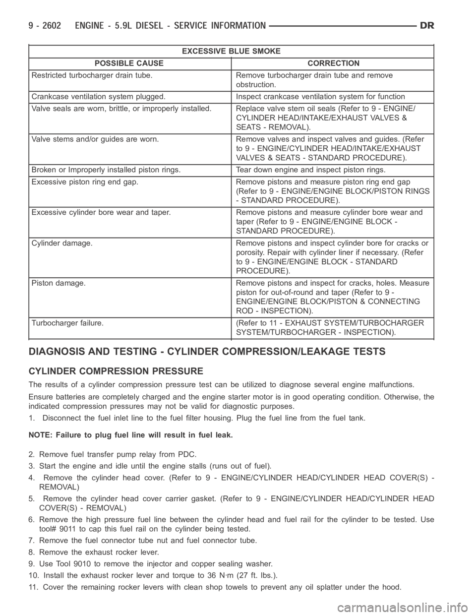
EXCESSIVE BLUE SMOKE
POSSIBLE CAUSE CORRECTION
Restricted turbocharger drain tube. Remove turbocharger drain tube and remove
obstruction.
Crankcase ventilation system plugged. Inspect crankcase ventilation system for function
Valve seals are worn, brittle, or improperly installed. Replace valve stemoilseals(Referto9-ENGINE/
CYLINDER HEAD/INTAKE/EXHAUST VALVES &
SEATS - REMOVAL).
Valve stems and/or guides are worn. Remove valves and inspect valves and guides. (Refer
to 9 - ENGINE/CYLINDER HEAD/INTAKE/EXHAUST
VALVES & SEATS - STANDARD PROCEDURE).
Broken or Improperly installed piston rings. Tear down engine and inspectpiston rings.
Excessive piston ring end gap. Remove pistons and measure piston ring end gap
(Refer to 9 - ENGINE/ENGINE BLOCK/PISTON RINGS
- STANDARD PROCEDURE).
Excessive cylinder bore wear and taper. Remove pistons and measure cylinder bore wear and
taper (Refer to 9 - ENGINE/ENGINE BLOCK -
STANDARD PROCEDURE).
Cylinder damage. Remove pistons and inspect cylinder bore for cracks or
porosity. Repair with cylinder liner if necessary. (Refer
to 9 - ENGINE/ENGINE BLOCK - STANDARD
PROCEDURE).
Piston damage. Remove pistons and inspect for cracks, holes. Measure
piston for out-of-round and taper (Refer to 9 -
ENGINE/ENGINE BLOCK/PISTON & CONNECTING
ROD - INSPECTION).
Turbocharger failure. (Refer to 11 - EXHAUST SYSTEM/TURBOCHARGER
SYSTEM/TURBOCHARGER - INSPECTION).
DIAGNOSIS AND TESTING - CYLINDER COMPRESSION/LEAKAGE TESTS
CYLINDER COMPRESSION PRESSURE
The results of a cylinder compressionpressure test can be utilized to diagnose several engine malfunctions.
Ensure batteries are completely charged and the engine starter motor is ingood operating condition. Otherwise, the
indicated compression pressures may not be valid for diagnostic purposes.
1. Disconnect the fuel inlet line to the fuel filter housing. Plug the fuel line from the fuel tank.
NOTE: Failure to plug fuel line will result in fuel leak.
2. Remove fuel transfer pump relay from PDC.
3. Start the engine and idle until the engine stalls (runs out of fuel).
4. Remove the cylinder head cover. (Refer to 9 - ENGINE/CYLINDER HEAD/CYLINDER HEAD COVER(S) -
REMOVAL)
5. Remove the cylinder head cover carrier gasket. (Refer to 9 - ENGINE/CYLINDER HEAD/CYLINDER HEAD
COVER(S) - REMOVAL)
6. Remove the high pressure fuel line between the cylinder head and fuel rail for the cylinder to be tested. Use
tool# 9011 to cap this fuel rail on the cylinder being tested.
7. Remove the fuel connector tube nut and fuel connector tube.
8. Remove the exhaust rocker lever.
9. Use Tool 9010 to remove the injector and copper sealing washer.
10. Install the exhaust rocker lever and torque to 36 Nꞏm (27 ft. lbs.).
11. Cover the remaining rocker levers with clean shop towels to prevent anyoil splatter under the hood.
Page 1917 of 5267
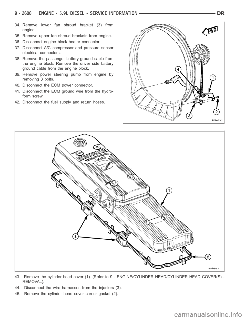
34. Remove lower fan shroud bracket (3) from
engine.
35. Remove upper fan shroud brackets from engine.
36. Disconnect engine block heater connector.
37. Disconnect A/C compressor and pressure sensor
electrical connectors.
38. Remove the passenger battery ground cable from
the engine block. Remove the driver side battery
ground cable from the engine block.
39. Remove power steering pump from engine by
removing 3 bolts.
40. Disconnect the ECM power connector.
41. Disconnect the ECM ground wire from the hydro-
form screw.
42. Disconnect the fuel supply and return hoses.
43. Remove the cylinder head cover (1). (Refer to 9 - ENGINE/CYLINDER HEAD/CYLINDER HEAD COVER(S) -
REMOVAL).
44. Disconnect the wire harnesses from the injectors (3).
45. Remove the cylinder head cover carrier gasket (2).