2006 DODGE RAM SRT-10 check oil
[x] Cancel search: check oilPage 1440 of 5267
When Monitored:
With the ignition key on and the engine speed greater than 0 RPM.
Set Condition:
When the PCM regulates the generator field and there are no detected field problems, but the voltage output
does not decrease.
Possible Causes
(K20) GENERATOR FIELD CONTROL CIRCUIT SHORTED TO GROUND
GENERATOR FIELD COIL SHORTED TO GROUND
BATTERY TEMPERATURE SENSOR
PCM
Always perform the Pre-Diagnostic Troubleshooting procedure before proceeding. (Refer to 9 - ENGINE -
DIAGNOSIS AND TESTING)
Diagnostic Test
1.CHARGING SYSTEM OPERATION
NOTE: Battery must be fully charged and be capable of passing a load test.
NOTE: Generator Belt tension and condition must be checked before continuing.
Ignition on, engine not running.
With the scan tool, read DTCs and the related Freeze Frame data then clear theDTCs.
With scan tool, actuate the Generator Field Driver.
With a 12-volt test light connected to ground, backprobe the (K20) Gen Field Control circuit in the back of Generator
Field harness connector.
Does the test light illuminate brightly and flash?
Ye s>>
Go To 2
No>>
Refer to the INTERMITTENT CONDITION Diagnostic Procedure.
Perform the POWERTRAIN VERIFICATION TEST. (Refer to 9 - ENGINE - STANDARD PROCEDURE)
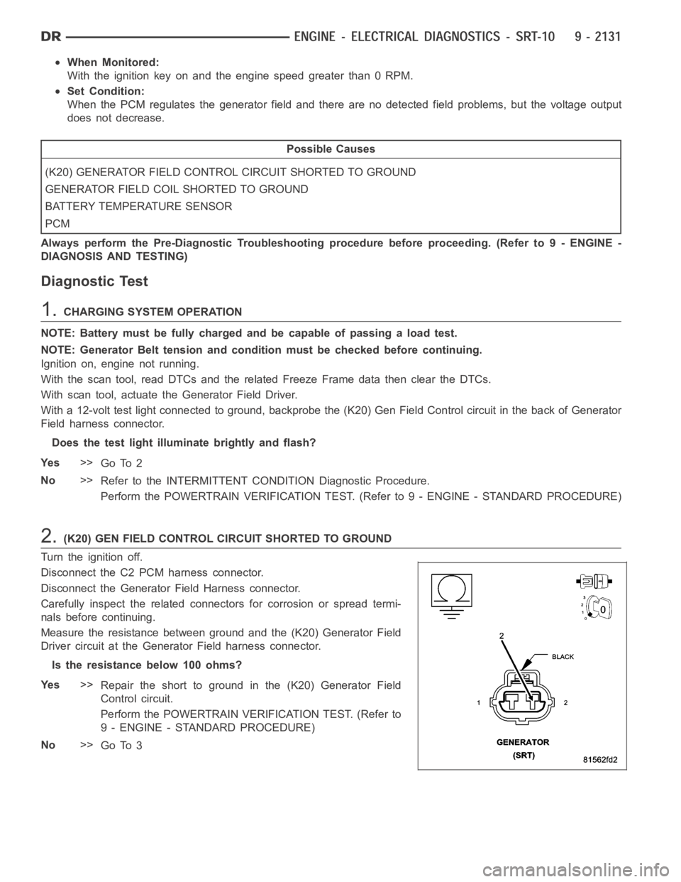
2.(K20) GEN FIELD CONTROL CIRCUIT SHORTED TO GROUND
Turn the ignition off.
Disconnect the C2 PCM harness connector.
Disconnect the Generator Field Harness connector.
Carefully inspect the related connectors for corrosion or spread termi-
nals before continuing.
Measure the resistance between ground and the (K20) Generator Field
Driver circuit at the Generator Field harness connector.
Istheresistancebelow100ohms?
Ye s>>
Repair the short to ground in the (K20) Generator Field
Control circuit.
Perform the POWERTRAIN VERIFICATION TEST. (Refer to
9 - ENGINE - STANDARD PROCEDURE)
No>>
Go To 3
Page 1441 of 5267
3.GENERATOR FIELD COIL SHORTED TO GROUND
Measure the resistance between ground and the Generator Field terminals on the Generator.
Istheresistancebelow100ohms?
Ye s>>
Replace or repair the Generator Field Coil for a short to ground.
Perform the POWERTRAIN VERIFICATION TEST. (Refer to 9 - ENGINE - STANDARD PROCEDURE)
No>>
Go To 4
4.BATTERY TEMPERATURE SENSOR
Connect the PCM harness connectors and the Generator harness connector.
Ignition on, engine not running.
With the scan tool in Inputs/Outputs, read the Batt Temp Sensor value.
Using a thermometer measure under hood temperature near Battery tray.
Is the temperature within 10 deg of Battery temperature?
Ye s>>
Go To 5
No>>
Replace the Battery Temperature Sensor.
Perform the POWERTRAIN VERIFICATION TEST. (Refer to 9 - ENGINE - STANDARD PROCEDURE)
5.PCM
NOTE: Before continuing, check the PCM harness connector terminals for corrosion, damage, or terminal
push out. Repair as necessary.
Using the schematics as a guide, inspect the wire harness and connectors. Pay particular attention to all Power and
Ground circuits.
If there are no possible causes remaining, view repair.
Repair
Replace and program the Powertrain Control Module per Service Information.
Perform the POWERTRAIN VERIFICATION TEST. (Refer to 9 - ENGINE - STANDARD PROCEDURE)
Page 1451 of 5267
When Monitored:
With the ignition key on and the engine running over 1500 RPM after 25 seconds.
Set Condition:
When the PCM regulates the generator field and there are no detected field problems, but the voltage output
does not increase.
Possible Causes
BATTERY TEMPERATURE SENSOR
RESISTANCE IN THE BATTERY POSITIVE CIRCUIT
(K125) GENERATOR FIELD SOURCE CIRCUIT OPEN
RESISTANCE IN THE GENERATOR GROUND
(K125) GENERATOR FIELD SOURCE CIRCUIT SHORTED TO GROUND
(K20) GENERATOR FIELD CONTROL CIRCUIT OPEN
RESISTANCE IN THE GENERATOR FIELD COIL
PCM
Always perform the Pre-Diagnostic Troubleshooting procedure before proceeding. (Refer to 9 - ENGINE -
DIAGNOSIS AND TESTING)
Diagnostic Test
1.CHARGING VOLTAGE BELOW 15.1 VOLTS
Turn the ignition off.
NOTE: Battery must be fully charged and capable of passing a battery load test.
NOTE: Generator Belt tension and condition must be checked before continuing.
NOTE: Inspect the vehicle for any aftermarket accessories that may exceedthe maximum Generator output.
WARNING: When the engine is operating, do not stand in direct line of the fan. Do not put your hands near
the pulley, belts, or fan. Do no wear loose clothing.
Start the engine.
Record all DTCs and the related Freeze Frame data.
With the scan tool, read the target charging voltage.
Is the target charging voltage above 15.1 volts?
Ye s>>
Refer to the INTERMITTENT CONDITION Diagnostic Procedure.
Perform the POWERTRAIN VERIFICATION TEST. (Refer to 9 - ENGINE - STANDARD PROCEDURE)
No>>
Go To 2
2.BATTERY TEMPERATURE SENSOR
Turn the ignition off.
NOTE: Generator Belt tension and condition must be checked before continuing.
Start the engine.
Allow the engine to reach normal operating temperature.
With the scan tool in sensors, read the Battery Temp Sensor value.
Using a Thermometer, measure under hood temperature.
Is the temperature within 10° F of Battery temperature?
Ye s>>
Go To 3
No>>
Replace the Battery Temperature Sensor.
Perform the POWERTRAIN VERIFICATION TEST. (Refer to 9 - ENGINE - STANDARD PROCEDURE)
Page 1469 of 5267
Possible Causes
A/C SELECT CIRCUIT OPEN
A/C SELECT IN HVAC
PCM
A/C REQUEST CIRCUIT OPEN
REFRIGERATION SYSTEM NOT PROPERLY CHARGED
HIGH PRESS CUT-OFF SWITCH
LOW PRESSURE SWITCH
A/CCLUTCHCOIL
A/C COMPRESSOR CLUTCH GROUND CIRCUIT OPEN
(C3) A/C CLUTCH RELAY OUTPUT CIRCUIT OPEN
FUSED B+ CIRCUIT OPEN
A/CCLUTCHRELAY
Always perform the Pre-Diagnostic Troubleshooting procedure before proceeding. (Refer to 9 - ENGINE -
DIAGNOSIS AND TESTING)
Diagnostic Test
1.DTC AND COMMUNICATION PRESENT
Ignition on, engine not running.
Verify that communication with the HVAC and PCM is available over the BUS.
With the scan tool, check for DTCs in the PCM and HVAC module.
Are any A/C DTC’s or communication failures present?
Ye s>>
Diagnose the related DTC(s) or BUS failure before continuing.
Perform BODY VERIFICATION TEST - VER 1.
No>>
Go To 2
2.A/C SELECT CIRCUIT OPEN
Engine running.
With the scan tool, read the A/C Select status in the PCM.
Turn the A/C Switch on and off a few times.
Does the A/C Select state change?
Ye s>>
Go To 3
No>>
Go To 12
3.A/C REQUEST CIRCUIT OPEN
Engine Running.
Turn the A/C system on and the fan on high.
With the scan tool in Inputs/Outputs, read the A/C request state.
Does the A/C request state change?
Ye s>>
Go To 4
No>>
Repair the open in the A/C Request circuit.
Perform BODY VERIFICATION TEST - VER 1.
Page 1470 of 5267
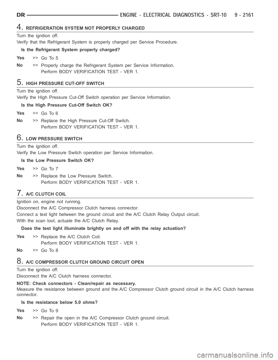
4.REFRIGERATION SYSTEM NOT PROPERLY CHARGED
Turn the ignition off.
Verify that the Refrigerant System is properly charged per Service Procedure.
Is the Refrigerant System properly charged?
Ye s>>
Go To 5
No>>
Properly charge the Refrigerant System per Service Information.
Perform BODY VERIFICATION TEST - VER 1.
5.HIGH PRESSURE CUT-OFF SWITCH
Turn the ignition off.
Verify the High Pressure Cut-Off Switch operation per Service Information.
Is the High Pressure Cut-Off Switch OK?
Ye s>>
Go To 6
No>>
Replace the High Pressure Cut-Off Switch.
Perform BODY VERIFICATION TEST - VER 1.
6.LOW PRESSURE SWITCH
Turn the ignition off.
Verify the Low Pressure Switch operation per Service Information.
Is the Low Pressure Switch OK?
Ye s>>
Go To 7
No>>
Replace the Low Pressure Switch.
Perform BODY VERIFICATION TEST - VER 1.
7.A/C CLUTCH COIL
Ignition on, engine not running.
Disconnect the A/C Compressor Clutch harness connector.
Connect a test light between the ground circuit and the A/C Clutch Relay Output circuit.
With the scan tool, actuate the A/C Clutch Relay.
Does the test light illuminate brightly on and off with the relay actuation?
Ye s>>
Replace the A/C Clutch Coil.
Perform BODY VERIFICATION TEST - VER 1.
No>>
Go To 8
8.A/C COMPRESSOR CLUTCH GROUND CIRCUIT OPEN
Turn the ignition off.
Disconnect the A/C Clutch harness connector.
NOTE: Check connectors - Clean/repair as necessary.
Measure the resistance between ground and the A/C Compressor Clutch ground circuit in the A/C Clutch harness
connector.
Is the resistance below 5.0 ohms?
Ye s>>
Go To 9
No>>
Repair the open in the A/C Compressor Clutch ground circuit.
Perform BODY VERIFICATION TEST - VER 1.
Page 1471 of 5267
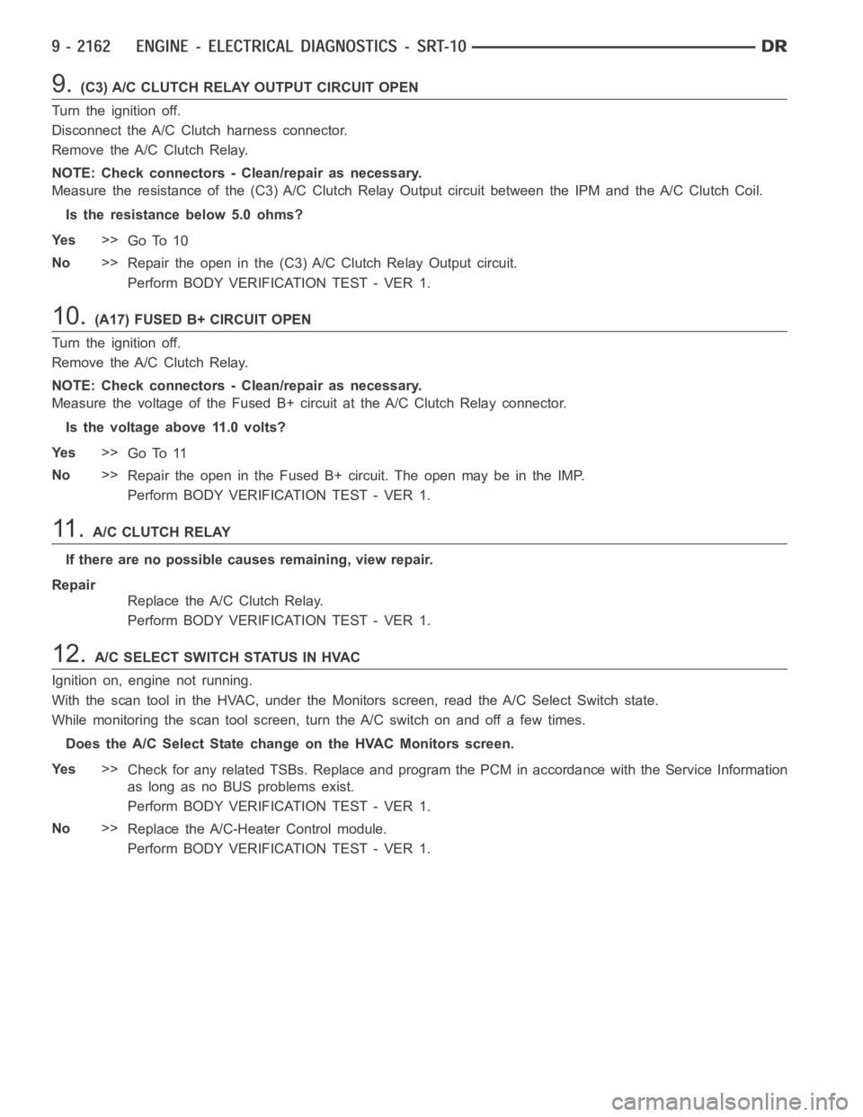
9.(C3) A/C CLUTCH RELAY OUTPUT CIRCUIT OPEN
Turn the ignition off.
Disconnect the A/C Clutch harness connector.
Remove the A/C Clutch Relay.
NOTE: Check connectors - Clean/repair as necessary.
Measure the resistance of the (C3) A/C Clutch Relay Output circuit betweenthe IPM and the A/C Clutch Coil.
Is the resistance below 5.0 ohms?
Ye s>>
Go To 10
No>>
Repair the open in the (C3) A/C Clutch Relay Output circuit.
Perform BODY VERIFICATION TEST - VER 1.
10.(A17) FUSED B+ CIRCUIT OPEN
Turn the ignition off.
Remove the A/C Clutch Relay.
NOTE: Check connectors - Clean/repair as necessary.
Measure the voltage of the Fused B+ circuit at the A/C Clutch Relay connector.
Is the voltage above 11.0 volts?
Ye s>>
Go To 11
No>>
Repair the open in the Fused B+ circuit. The open may be in the IMP.
Perform BODY VERIFICATION TEST - VER 1.
11 .A/C CLUTCH RELAY
If there are no possible causes remaining, view repair.
Repair
Replace the A/C Clutch Relay.
Perform BODY VERIFICATION TEST - VER 1.
12.A/CSELECTSWITCHSTATUSINHVAC
Ignition on, engine not running.
With the scan tool in the HVAC, under the Monitors screen, read the A/C Select Switch state.
While monitoring the scan tool screen, turn the A/C switch on and off a few times.
Does the A/C Select State change on the HVAC Monitors screen.
Ye s>>
Check for any related TSBs. Replace and program the PCM in accordance with the Service Information
as long as no BUS problems exist.
Perform BODY VERIFICATION TEST - VER 1.
No>>
Replace the A/C-Heater Control module.
Perform BODY VERIFICATION TEST - VER 1.
Page 1474 of 5267
4.RESISTANCE IN THE GENERATOR GROUND
Start the engine.
Warm the engine to operating temperature.
CAUTION: Make sure all wires are clear of the engine’s moving parts.
Measure the voltage between the Generator case and Battery Negative Post.
Is the voltage above 0.1 of a volt?
Ye s>>
Repair the excessive resistance in the Generator Ground circuit between the Generator Case and Bat-
tery Ground side.
Perform the POWERTRAIN VERIFICATION TEST. (Refer to 9 - ENGINE - STANDARD PROCEDURE)
No>>
Go To 5
5.GENERATOR FIELD COIL HIGH RESISTANCE
Turn the ignition off.
Disconnect the Generator Field harness connector at back of the Generator.
Measure resistance across the Generator Field Terminals at the Generator.
Is the resistance above 15 ohms?
Ye s>>
Replace or repair the Generator as necessary.
Perform the POWERTRAIN VERIFICATION TEST. (Refer to 9 - ENGINE - STANDARD PROCEDURE)
No>>
Go To 6
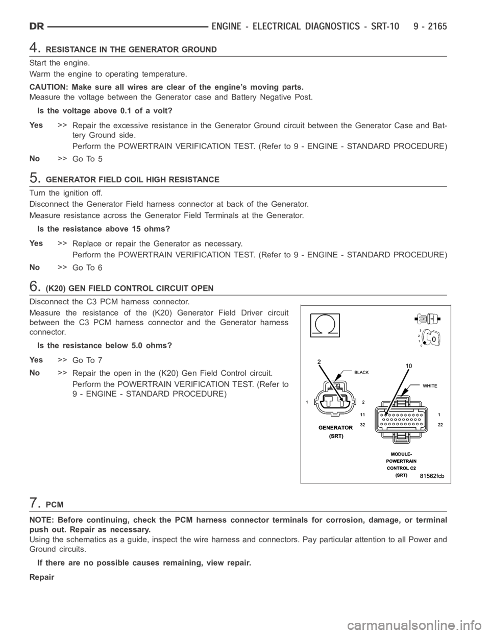
6.(K20) GEN FIELD CONTROL CIRCUIT OPEN
Disconnect the C3 PCM harness connector.
Measure the resistance of the (K20) Generator Field Driver circuit
between the C3 PCM harness connector and the Generator harness
connector.
Is the resistance below 5.0 ohms?
Ye s>>
Go To 7
No>>
Repair the open in the (K20) Gen Field Control circuit.
Perform the POWERTRAIN VERIFICATION TEST. (Refer to
9 - ENGINE - STANDARD PROCEDURE)
7.PCM
NOTE: Before continuing, check the PCM harness connector terminals for corrosion, damage, or terminal
push out. Repair as necessary.
Using the schematics as a guide, inspect the wire harness and connectors. Pay particular attention to all Power and
Ground circuits.
If there are no possible causes remaining, view repair.
Repair
Page 1488 of 5267
REMOVAL ................................. 2255
INSTALLATION ............................. 2256
PLATE-FLEX
REMOVAL ................................. 2257
INSTALLATION ............................. 2257
ROD-PISTON AND CONNECTING
DESCRIPTION ............................. 2258
STANDARD PROCEDURE
CONNECTING ROD BEARING FITTING .... 2258
STANDARD PROCEDURE - PISTON
FITTING.................................. 2261
REMOVAL ................................. 2262
CLEANING ................................. 2262
INSPECTION ............................... 2262
INSTALLATION ............................. 2263
RINGS-PISTON
STANDARD PROCEDURE - PISTON RING
FITTING .................................. 2265
DAMPER-CRANKSHAFT
REMOVAL ................................. 2268
INSTALLATION ............................. 2269
COVER-STRUCTURAL
DESCRIPTION ............................. 2270
OPERATION ............................... 2270
REMOVAL ................................. 2270
INSTALLATION ............................. 2270
MOUNT-FRONT
REMOVAL ................................. 2271
INSTALLATION ............................. 2273
MOUNT-REAR
REMOVAL ................................. 2275
INSTALLATION ............................. 2275
LUBRICATION
DESCRIPTION ............................. 2276
OPERATION ............................... 2276
DIAGNOSIS AND TESTING
DIAGNOSIS AND TESTING - ENGINE OIL
LEAK.................................... 2278
DIAGNOSIS AND TESTING - CHECKING
ENGINE OIL PRESSURE.................. 2279
DIAGNOSIS AND TESTING - REAR SEAL
AREA LEAKS............................. 2279
PAN-ENGINE OIL
DESCRIPTION ............................. 2280
REMOVAL ................................. 2281
CLEANING ................................. 2282
INSPECTION ............................... 2282
INSTALLATION ............................. 2282SWITCH-OIL PRESSURE
DESCRIPTION ............................. 2284
OPERATION ............................... 2284
REMOVAL ................................. 2284
INSTALLATION ............................. 2284
PUMP-ENGINE OIL
REMOVAL ................................. 2285
DISASSEMBLY . ............................ 2285
INSPECTION............................... 2285
ASSEMBLY................................ 2287
INSTALLATION ............................. 2287
FILTER-ENGINE OIL
REMOVAL ................................. 2288
INSTALLATION ............................. 2288
OIL
STANDARD PROCEDURE - ENGINE OIL
SERVICE ................................. 2289
MANIFOLD-INTAKE
DESCRIPTION ............................. 2291
DIAGNOSIS AND TESTING - INTAKE
MANIFOLD LEAKS ........................ 2291
REMOVAL ................................. 2291
INSTALLATION ............................. 2292
MANIFOLD-EXHAUST
DESCRIPTION ............................. 2294
REMOVAL ................................. 2294
INSTALLATION ............................. 2295
VALVE TIMING
DESCRIPTION ............................. 2297
OPERATION ............................... 2297
STANDARD PROCEDURE
MEASURING TIMING CHAIN WEAR ........ 2298
SERVICE PROCEDURE - TIMING
VERIFICATION........................... 2298
SHAFT-BALANCE
REMOVAL ................................. 2302
INSTALLATION ............................. 2303
SHAFT-IDLER
REMOVAL ................................. 2304
INSTALLATION ............................. 2304
COVER-TIMING
REMOVAL ................................. 2305
INSTALLATION ............................. 2306
CHAIN AND SPROCKETS-TIMING
REMOVAL ................................. 2307
INSPECTION............................... 2309
INSTALLATION ............................. 2310