Page 1631 of 2893
���
�´
�µ
�µ �µ
�µ
YES
NO YES
NO
19-139
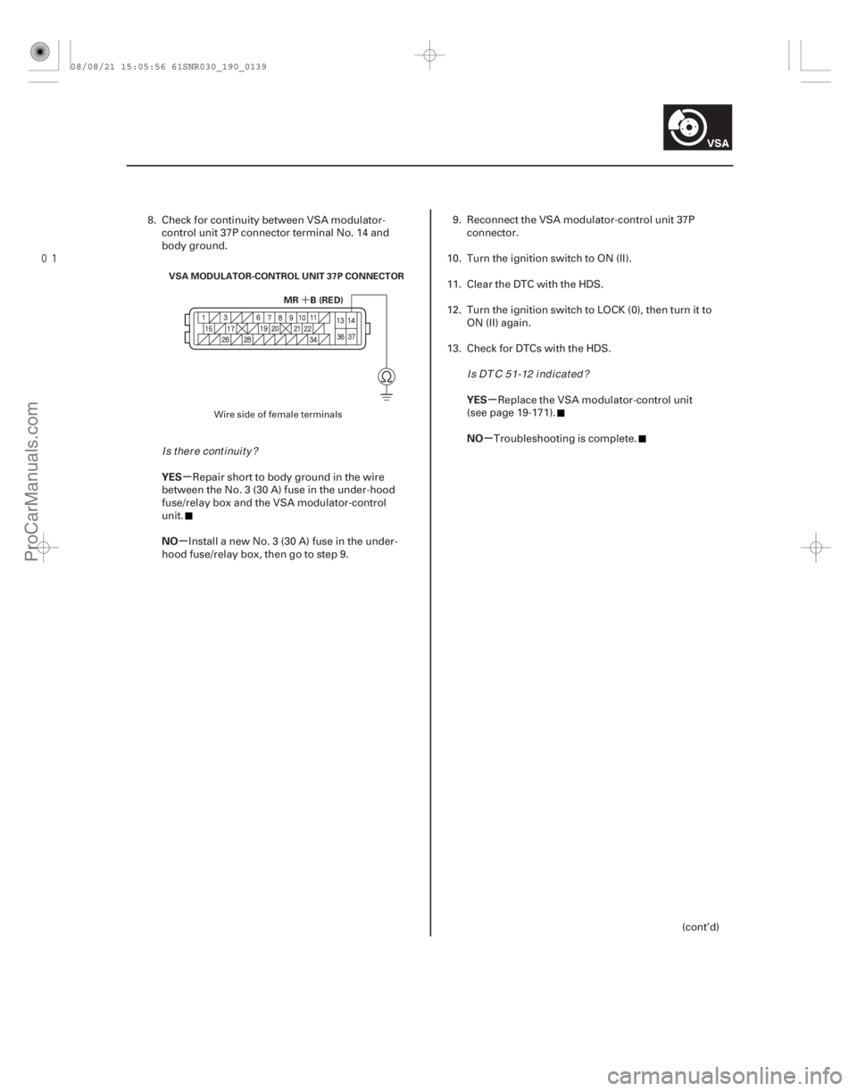
MR B (RED)
VSA MODULATOR-CONTROL UNIT 37P CONNECTOR
8. Check for continuity between VSA modulator-
control unit 37P connector terminal No. 14 and
body ground.
Repair short to body ground in the wire
between the No. 3 (30 A) fuse in the under-hood
fuse/relay box and the VSA modulator-control
unit.
Install a new No. 3 (30 A) fuse in the under-
hood fuse/relay box, then go to step 9. 9. Reconnect the VSA modulator-control unit 37P
connector.
10. Turn the ignition switch to ON (II).
11. Clear the DTC with the HDS.
12. Turn the ignition switch to LOCK (0), then turn it to ON (II) again.
13. Check for DTCs with the HDS.
Replace the VSA modulator-control unit
(see page 19-171).
Troubleshooting is complete.
(cont’d)
Wire side of female terminals
Is there continuity? I s DT C 5 1-12 i nd i cat ed ?
08/08/21 15:05:56 61SNR030_190_0139
ProCarManuals.com
DYNOMITE -2009-
Page 1632 of 2893
����
�´
�µ
�µ �µ
�µ
YES
NO YES
NO
DTC 52-12:
19-14019-140VSA System Components
DTC Troubleshooting (cont’d)
MR B (RED)
VSA MODULATOR-CONTROL U")
����
�(�#�'��������� �����
�������'�����
���������)����
�´
�µ
�µ �µ
�µ
YES
NO YES
NO
DTC 52-12:
19-14019-140VSA System Components
DTC Troubleshooting (cont’d)
MR B (RED)
VSA MODULATOR-CONTROL UNIT 37P CONNECTOR
14. Disconnect the VSA modulator-control unit 37P
connector (see step 2 on page 19- 171).
15. Measure the voltage between VSA modulator- control unit 37P connector terminal No. 14 and
body ground.
Check for loose terminals in the VSA
modulator-control unit 37P connector. If necessary,
substitute a known-good VSA modulator-control
unit (see page 19-171), and retest.
Repair open in the wire between the No. 3
(30 A) fuse in the under-hood fuse/relay box and
the VSA modulator-control unit. 1. Turn the ignition switch to ON (II).
2. Clear the DTC with the HDS.
3. Turn the ignition switch to LOCK (0), then turn it to
ON (II) again.
4. Operate any one of the four solenoids, as listed, in the VSA FUNCTION TEST five times with the HDS.
-LFT FT SOLENOID
-RT FT SOLENOID
-LFT REAR SOLENOID
-RT REAR SOLENOID
5. Check for DTCs with the HDS.
Replace the VSA modulator-control unit
(see page 19-171).
Intermittent failure, the system is OK at this
time.Motor Stuck OFF
Wire side of female terminals
Is there battery voltage? Is DTC 52-12 indicated?
08/08/21 15:05:56 61SNR030_190_0140
ProCarManuals.com
DYNOMITE -2009-
Page 1633 of 2893
����
�µ
�µ
�µ
�µ
DTC 53-01:
DTC 53-12:
YES
NO YES
NO
19-141
MR-GND (BLK)
VSA MODULATOR-CONTROL UNIT 37P CONNECTOR
Motor Relay Stuck ON 1
Motor Re")
���
�(�#�'��������� �����
�������'�������
�������)����
�µ
�µ
�µ
�µ
DTC 53-01:
DTC 53-12:
YES
NO YES
NO
19-141
MR-GND (BLK)
VSA MODULATOR-CONTROL UNIT 37P CONNECTOR
Motor Relay Stuck ON 1
Motor Relay Stuck ON 2
1. Turn the ignition switch to ON (II).
2. Clear the DTC with the HDS.
3. Turn the ignition switch to LOCK (0), then turn it to
ON (II) again.
4. Check for DTCs with the HDS.
Go to step 5.
Intermittent failure, the system is OK at this
time. Check for loose terminals at the VSA
modulator-control unit 37P connector. Refer to
intermittent failures troubleshooting (see page
19-98).
5. Turn the ignition switch to LOCK (0).
6. Disconnect the VSA modulator-control unit 37P connector (see step 2 on page 19- 171).7. Check for continuity between VSA modulator-
control unit 37P connector terminal No. 37 and
body ground.
Check for loose terminals in the VSA
modulator-control unit 37P connector. If necessary,
substitute a known-good VSA modulator-control
unit (see page 19-171), and retest.
Repair open in the wire between the VSA
modulator-control unit and body ground (G202).
Wire side of female terminals
I s DT C 5 3-01 or 5 3-12 i nd i cat ed ?
Is there continuity?
08/08/21 15:05:56 61SNR030_190_0141
ProCarManuals.com
DYNOMITE -2009-
Page 1634 of 2893
�����(�#���������� �����
��������������
�������)����
�µ
�µ �µ
�µ
DTC 54-03:
DTC 54-04:
DTC 54-21: DTC 56-01:
DTC 56-02:
DTC 56-11:
YES
NO YES
NO
19-")
�(�#�'��������� �����
�������'���������������)�����(�#�'��������� �����
�������'�������
�������)����
�µ
�µ �µ
�µ
DTC 54-03:
DTC 54-04:
DTC 54-21: DTC 56-01:
DTC 56-02:
DTC 56-11:
YES
NO YES
NO
19-14219-142VSA System Components
DTC Troubleshooting (cont’d)
Fail-safe Relay 1 Stuck ON
Fail-safe Relay 1 Stuck OFF
(Initial)
Fail-safe Relay 1 Stuck OFF
(Main) Initial VIG FET Stuck OFF
Initial VIG FET Stuck ON
VIG FET Stuck OFF
1. Turn the ignition switch to ON (II).
2. Clear the DTC with the HDS.
3. Turn the ignition switch to LOCK (0), then turn it to
ON (II) again.
4. Check for DTCs with the HDS.
Replace the VSA modulator-control unit
(see page 19-171).
Intermittent failure, the system is OK at this
time. 1. Turn the ignition switch to ON (II).
2. Clear the DTC with the HDS.
3. Turn the ignition switch to LOCK (0), then turn it to
ON (II) again.
4. Check for DTCs with the HDS.
Replace the VSA modulator-control unit
(see page 19-171).
Intermittent failure, the system is OK at this
time.
I s DT C 5 4-03, 5 4-04, or 5 4-21 i nd i cat ed ? Is DT C 56-01, 56-02, or 56-11 indicated?
08/08/21 15:05:57 61SNR030_190_0142
ProCarManuals.com
DYNOMITE -2009-
Page 1635 of 2893
����
�µ
�µ �µ
�µ
DTC 61-01:
DTC 61-21:
DTC 61-22:
DTC 61-23:
YES
NO YES
NO
19-143
VSA Modulator-control Unit
Initial IG Low Voltage
VSA Modulator-cont")
�(�#�'��������� �����
�������'���
���
�������)����
�µ
�µ �µ
�µ
DTC 61-01:
DTC 61-21:
DTC 61-22:
DTC 61-23:
YES
NO YES
NO
19-143
VSA Modulator-control Unit
Initial IG Low Voltage
VSA Modulator-control Unit
Power Source Low Voltage 1
VSA Modulator-control Unit
Power Source Low Voltage 2
VSA Modulator-control Unit
Power Source Low Voltage 3
1. Turn the ignition switch to ON (II).
2. Clear the DTC with the HDS.
3. Turn the ignition switch to LOCK (0), then start the
engine.
4. Check for DTCs with the HDS.
Go to step 5.
Intermittent failure, the system is OK at this
time. Check for loose terminals at the VSA
modulator-control unit 37P connector. Refer to
intermittent failures troubleshooting (see page
19-98).
5. Check and note BATTERY voltage in the VSA DATA LIST with the HDS.
6. Using a voltmeter, measure and note the voltage between the battery terminals.
NOTE: If the battery voltage is below 9.5 V, check
the battery (see page 22-67), and troubleshoot the
alternator regulator circuit (see page 4-28). 7. Compare the data list voltage noted in step 5 to the
battery voltage in step 6.
Intermittent failure, the system is OK at this
time. Check for loose terminals at the VSA
modulator-control unit 37P connector. Refer to
intermittent failures troubleshooting (see page
19-98). If the code resets after clearing, replace the
VSA modulator-control unit (see page 19-171).
Check for loose terminals in the VSA
modulator-control unit 37P connector. If necessary,
substitute a known-good VSA modulator-control
unit (see page 19-171), and retest.
I s DT C 61-01, 61-2 1, 61-2 2 , or 61-2 3 i nd i cat ed ? Is t he d i f f er ence bet w een t he t w o v ol t age
r ead i ngs l ess t han 3 V ?
08/08/21 15:05:57 61SNR030_190_0143
ProCarManuals.com
DYNOMITE -2009-
Page 1636 of 2893
�����(�#���������� �����
������������
�
�������)����
�µ
�µ
�µ
�µ �µ
�µ
DTC 62-21: DTC 64-11:
YES
NO
YES
NO YES
NO
19-14419-144VSA System Component")
�(�#�'��������� �����
�������'�������
�������)�����(�#�'��������� �����
�������'�����
�
�������)����
�µ
�µ
�µ
�µ �µ
�µ
DTC 62-21: DTC 64-11:
YES
NO
YES
NO YES
NO
19-14419-144VSA System Components
DTC Troubleshooting (cont’d)
VSA Modulator-control Unit IG
High Voltage Steering Angle Sensor Power
Circuit Short
1. Turn the ignition switch to ON (II).
2. Clear the DTC with the HDS.
3. Turn the ignition switch to LOCK (0), then start the
engine.
4. Check for DTCs with the HDS.
Go to step 5.
Intermittent failure, the system is OK at this
time.
5. Check and note BATTERY voltage in the VSA DATA LIST with the HDS.
6. Using a voltmeter, measure and note the voltage between the battery terminals.
NOTE: If the voltage is above 15.1 V, troubleshoot
the alternator regulator circuit (see page 4-28).
7. Compare the data list voltage noted in step 5 to the battery voltage in step 6.
Intermittent failure, the system is OK at this
time. Check for loose terminals at the VSA
modulator-control unit 37P connector. Refer to
intermittent failures troubleshooting (see page
19-98). If the code resets after clearing, replace the
VSA modulator-control unit (see page 19-171).
Replace the VSA modulator-control unit
(see page 19-171), and retest. 1. Turn the ignition switch to ON (II).
2. Clear the DTC with the HDS.
3. Turn the ignition switch to LOCK (0), then turn it to
ON (II) again.
4. Check for DTCs with the HDS.
Go to step 5.
Intermittent failure, the system is OK at this
time.
5. Turn the ignition switch to LOCK (0).
6. Disconnect the steering angle sensor 5P connector.
7. Disconnect the VSA modulator-control unit 37P connector (see step 2 on page 19-171).
Is DT C 62-21 indicated?
Is t he d i f f er ence bet w een t he t w o v ol t ager ead i ngs l ess t han 3 V ? Is DTC 64-11 indicated?
08/08/21 15:05:57 61SNR030_190_0144
ProCarManuals.com
DYNOMITE -2009-
Page 1637 of 2893
����
�µ
�µ �µ
�µ
YES
NO YES
NO
DTC 64-12:
19-14519-145
STEERING ANGLE SENSOR 5P CONNECTOR
SVCC (ORN)
8. Check for continuity between steering ang")
���
�(�#�'��������� �����
�������'�����
���������)����
�µ
�µ �µ
�µ
YES
NO YES
NO
DTC 64-12:
19-14519-145
STEERING ANGLE SENSOR 5P CONNECTOR
SVCC (ORN)
8. Check for continuity between steering angle sensor5P connector terminal No. 5 and body ground.
Repair short to body ground in the wire
between the steering angle sensor and the VSA
modulator-control unit.
Replace the VSA modulator-control unit
(see page 19-171). 1. Turn the ignition switch to ON (II).
2. Clear the DTC with the HDS.
3. Turn the ignition switch to LOCK (0), then turn it to
ON (II) again.
4. Check for DTCs with the HDS.
Go to step 5.
Intermittent failure, the system is OK at this
time. Check for loose terminals between the
steering angle sensor 5P connector and the VSA
modulator-control unit 37P connector. Refer to
intermittent failures troubleshooting (see page
19-98).
5. Turn the ignition switch to LOCK (0).
6. Disconnect the steering angle sensor 5P connector.
7. Disconnect the VSA modulator-control unit 37P connector (see step 2 on page 19-171).
(cont’d)Steering Angle Sensor Power
Circuit Open
Wire side of female terminals
Is there continuity? Is DTC 64-12 indicated?
08/08/21 15:05:57 61SNR030_190_0145
ProCarManuals.com
DYNOMITE -2009-
Page 1638 of 2893

VSA MODULATOR-CONTROL UNIT 37P CONNECTOR
STEERING ANGLE SENSOR 5P CONNECTOR
SVCC (ORN)SVCC (ORN) STEER")
���
����
�µ
�µ �µ
�µ
YES
NO YES
NO
19-146VSA System Components
DTC Troubleshooting (cont’d)
VSA MODULATOR-CONTROL UNIT 37P CONNECTOR
STEERING ANGLE SENSOR 5P CONNECTOR
SVCC (ORN)SVCC (ORN) STEERING ANGLE SENSOR 5P CONNECTOR
SVCC (ORN)
8. Check for continuity between VSA modulator-control unit 37P connector terminal No. 7 and
steering angle sensor 5P connector terminal No. 5.
Go to step 9.
Repair open in the wire between the steering
angle sensor and the VSA modulator-control
unit.
9. Turn the ignition switch to ON (II). 10. Measure the voltage between steering angle
sensor 5P connector terminal No. 5 and body
ground.
Repair short to power in the wire between
the steering angle sensor and the VSA modulator-
control unit.
Check for loose terminals in the VSA
modulator-control unit 37P connector. If necessary,
substitute a known-good VSA modulator-control
unit (see page 19-171), and retest.
Wire side of female terminals Wire side of female terminals
Wire side of female terminals
Is there continuity?Is t her e 0.1 V or mor e?
08/08/21 15:05:57 61SNR030_190_0146
ProCarManuals.com
DYNOMITE -2009-