Page 1578 of 2893
����
�µ
�µ
�µ
�µ
DTC 86-01:
YES
NO Sign ECM/PCM
Connector A
(44P) Terminal
YES
NO
ABS Modulator-
control Unit 25P
Connector Terminal
19-85
CAN-H")
���
�(�#�'��������� �����
�������'�������
�������)����
�µ
�µ
�µ
�µ
DTC 86-01:
YES
NO Sign ECM/PCM
Connector A
(44P) Terminal
YES
NO
ABS Modulator-
control Unit 25P
Connector Terminal
19-85
CAN-H (WHT)
CAN-L (RED)
ECM/PCM CONNECTOR A (44P) CAN-L (RED)
CAN-H (WHT) ABS MODULATOR-CONTROL UNIT 25P CONNECTOR
F-CAN Bus-off Malfunction
1. Turn the ignition switch to ON (II).
2. Clear the DTC with the HDS.
3. Turn the ignition switch to LOCK (0), then turn it to
ON (II) again.
4. Check for DTCs with the HDS.
Go to step 5.
Intermittent failure, the system is OK at this
time. Check for loose terminals between ECM/PCM
connector A (44P) and the ABS modulator-control
unit 25P connector. Refer to intermittent failures
troubleshooting (see page 19-50).
5. Turn the ignition switch to LOCK (0).
6. Short the SCS line with the HDS.
7. Disconnect ECM/PCM connector A (44P).
8. Disconnect the ABS modulator-control unit 25P connector (see step 2 on page 19-90). 9. Check for continuity between ABS modulator-
control unit 25P connector terminal and ECM/PCM
connector A (44P) terminal (see table).
CAN-L No. 17 No. 37
CAN-H No. 1 No. 36
Check for loose terminals in the ABS
modulator-control unit 25P connector. If necessary,
substitute a known-good ABS modulator-control
unit (see page 19-90), and retest.
Repair open in the wire between the ECM/
PCM and the ABS modulator-control unit.
Wire side of female terminals
Terminal side of female terminalsIs DTC 86-01 indicated? Is there continuity?
08/08/21 15:03:16 61SNR030_190_0085
ProCarManuals.com
DYNOMITE -2009-
Page 1579 of 2893
����
�µ
�µ
�µ
�µ
DTC 86-24:
DTC 86-25:
YES
NO Sign ECM/PCM
Connector A
(44P) Terminal
YES
NO
ABS Modulator-
control Unit 25P
Connector Terminal
1")
���
�(�#�'��������� �����
�������'���������������)����
�µ
�µ
�µ
�µ
DTC 86-24:
DTC 86-25:
YES
NO Sign ECM/PCM
Connector A
(44P) Terminal
YES
NO
ABS Modulator-
control Unit 25P
Connector Terminal
19-86 ABS Components
DTC Troubleshooting (cont’d)
CAN-H (WHT)
CAN-L (RED)
ECM/PCM CONNECTOR A (44P) CAN-L (RED)
CAN-H (WHT) ABS MODULATOR-CONTROL UNIT 25P CONNECTOR
F-CAN Communication with
Engine Malfunction
F-CAN Communication with
Engine Malfunction
1. Turn the ignition switch to ON (II).
2. Clear the DTC with the HDS.
3. Test-drive the vehicle at 10 km/h (7 mph) or more.
NOTE: Drive the vehicle on the road, not on a lift.
4. Check for DTCs with the HDS.
Go to step 5.
Intermittent failure, the system is OK at this
time. Check for loose terminals between ECM/PCM
connector A (44P) and the ABS modulator-control
unit 25P connector. Refer to intermittent failures
troubleshooting (see page 19-50).
5. Turn the ignition switch to LOCK (0).
6. Short the SCS line with the HDS.
7. Disconnect ECM/PCM connector A (44P).
8. Disconnect the ABS modulator-control unit 25P connector (see step 2 on page 19-90). 9. Check for continuity between ABS modulator-
control unit 25P connector terminal and ECM/PCM
connector A (44P) terminal (see table).
CAN-L No. 17 No. 37
CAN-H No. 1 No. 36
Go to step 10.
Repair open in the wire between the ECM/
PCM and the ABS modulator-control unit.
Wire side of female terminals
Terminal side of female terminals
Is DT C 86-24 and/ or 86-25 indicated? Is there continuity?
08/08/21 15:03:17 61SNR030_190_0086
ProCarManuals.com
DYNOMITE -2009-
Page 1580 of 2893
����
�µ
�µ �µ
�µ
YES
NO YES
NO
DTC 86-FF:
19-8719-87
10. Reconnect all connectors.
11. Update the ECM/PCM if it does not have the latest
software (see")
�(�#�'��������� �����
�������'���������������)����
�µ
�µ �µ
�µ
YES
NO YES
NO
DTC 86-FF:
19-8719-87
10. Reconnect all connectors.
11. Update the ECM/PCM if it does not have the latest
software (see page 11-227), or substitute a known-
good ECM/PCM (see page 11-7).
12. Clear the DTC with the HDS.
13. Test-drive the vehicle at 10 km/h (7 mph) or more.
NOTE: Drive the vehicle on the road, not on a lift.
14. Check for DTCs with the HDS.
Replace the ABS modulator-control unit
(see page 19-90).
If the ECM/PCM was updated, troubleshooting
is complete. If the ECM/PCM was substituted,
replace the original ECM/PCM (see page 11-228). 1. Turn the ignition switch to ON (II).
2. Clear the DTC with the HDS.
3. Turn the ignition switch to LOCK (0), then turn it to
ON (II) again.
4. Check for DTCs with the HDS.
Replace the ABS modulator-control unit
(see page 19-90).
Intermittent failure, the system is OK at this
time.F-CAN Communication with ABS
Malfunction
Is DT C 86-24 and/ or 86-25 indicated? Is DTC 86-FF indicated?
08/08/21 15:03:17 61SNR030_190_0087
ProCarManuals.com
DYNOMITE -2009-
Page 1581 of 2893
����
�µ
�µ
�µ
�µ �µ
�µ
�µ
�µ
ABS indicator and brake system indicator do
not go off
YES
NO
YES
NO YES
NO
YES
NO
19-88ABS Components")
����
�����
�(�#�'�����������
���������������������������)����
�µ
�µ
�µ
�µ �µ
�µ
�µ
�µ
ABS indicator and brake system indicator do
not go off
YES
NO
YES
NO YES
NO
YES
NO
19-88ABS Components
Symptom Troubleshooting
ABS MODULATOR-CONTROL UNIT 25P CONNECTOR
IG1 (YEL)*
*1: ’06 model
*2: ’07 model (GRY)*
ABS MODULATOR-CONTROL UNIT 25P CONNECTOR
IG1 (YEL)*
*1: ’06 model
*2: ’07 model (GRY)*
1
2
12
1. Turn the ignition switch to LOCK (0).
2. Check the No. 4 (7.5 A) fuse in the under-dash fuse/ relay box.
Go to step 3.
Reinstall the checked fuse, then go to step 8.
3. Disconnect the ABS modulator-control unit 25P connector (see step 2 on page 19-90).
4. Check for continuity between ABS modulator- control unit 25P connector terminal No. 16 and
body ground.
Repair short to body ground in the wire
between the No. 4 (7.5 A) fuse in the under-dash
fuse/relay box and the ABS modulator-control
unit.
Install a new No. 4 (7.5 A) fuse in the under-
dashfuse/relaybox,thengotostep5. 5. Reconnect the ABS modulator-control unit 25P
connector.
6. Turn the ignition switch to ON (II).
7. Check the ABS indicator and the brake system indicator for several sec onds when the ignition
switch is tuned to ON (II).
Troubleshooting is complete.
Replace the ABS modulator-control unit
(see page 19-90).
8. Disconnect the ABS modulator-control unit 25P connector (see step 2 on page 19-90).
9. Turn the ignition switch to ON (II).
10. Measure the voltage between ABS modulator- control unit 25P connector terminal No. 16 and
body ground.
Go to step 11.
Repair open in the wire between the No. 4
(7.5 A) fuse in the under-dash fuse/relay box and
the ABS modulator-control unit.
11. Turn the ignition switch to LOCK (0).
Wire side of female terminals
Wire side of female terminals
Isthefuseblown?
Is there continuity? Does t he i nd i cat or s come on t hen go of f ?
Is there battery voltage?
08/08/21 15:03:17 61SNR030_190_0088
ProCarManuals.com
DYNOMITE -2009-
Page 1583 of 2893
�
��
Removal
19-90ABS Components
ABS Modulator-Control Unit Removal and Installation
A
B C
15 N·m
(1.5 kgf·m, 11 lbf·ft)
D
E
I F
G
H 15 N·m
(1.5 k")
���
�(�#�'�����������
�����������
��������� �����)�
��
Removal
19-90ABS Components
ABS Modulator-Control Unit Removal and Installation
A
B C
15 N·m
(1.5 kgf·m, 11 lbf·ft)
D
E
I F
G
H 15 N·m
(1.5 kgf·m, 11 lbf·ft)
9.8 N·m
(1.0 kgf·m, 7.2 lbf·ft) 9.8 N·m
(1.0 kgf·m, 7.2 lbf·ft)
NOTE:
Do not spill brake fluid on the vehicle; it may damage the paint; if brake fluid gets on the paint, wash it off immediately with water.
Be careful not to damage or deform the brake lines during removal and installation.
Plug the ends of the hoses and the joints to prevent spilling brake fluid.
1. Turn the ignition switch to LOCK (0).
2. Disconnect the ABS modulator-control unit 25P connector (A) by pu lling up the lock (B); the connector disconnects
itself.
3. Disconnect the six brake lines from the ABS modulator-control unit. NOTE: Brake lines are connected to the master cylinder (C) and to the right-front (D), the left-rear (E), the right-rear
(F), and the left-front (G) brake systems.
4. Remove the ABS modulator-control unit (H) with the brackets (I) from the body.
5. Remove the ABS modulator-control unit from the brackets.
6. Separate the bracket if necessary.
08/08/21 15:03:18 61SNR030_190_0090
ProCarManuals.com
DYNOMITE -2009-
Page 1585 of 2893
���
�(�#�'�����������
�������������������
� �����)�
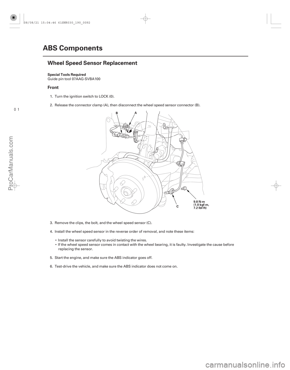
�� Special Tools Required
Front
19-92ABS Components
Wheel Speed Sensor Replacement
A
B
C9.8 N·m
(1.0 kgf·m,
7.2 lbf·ft)
Guide pin tool 07AAG-SVBA100
1. Turn the ignition switch to LOCK (0).
2. Release the connector clamp (A), then disconnect the wheel speed sensor connector (B).
3. Remove the clips, the bolt, and the wheel speed sensor (C).
4. Install the wheel speed sensor in the reverse order of removal, and note these items: Install the sensor carefully to avoid twisting the wires.
If the wheel speed sensor comes in contact with the wheel bearing, it is faulty. Investigate the cause beforereplacing the sensor.
5. Start the engine, and make sure the ABS indicator goes off.
6. Test-drive the vehicle, and make sure the ABS indicator does not come on.
08/08/21 15:04:46 61SNR030_190_0092
ProCarManuals.com
DYNOMITE -2009-
Page 1586 of 2893
����
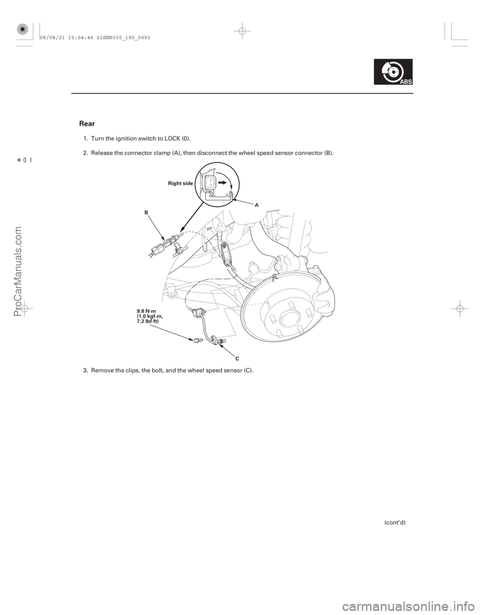
Rear
19-93
Right side
9.8 N·m
(1.0 kgf·m,
7.2 lbf·ft) A
B
C
1. Turn the ignition switch to LOCK (0).
2. Release the connector clamp (A), then disconnect the wheel speed sensor connector (B).
3. Remove the clips, the bolt, and the wheel speed sensor (C). (cont’d)
08/08/21 15:04:46 61SNR030_190_0093
ProCarManuals.com
DYNOMITE -2009-
Page 1589 of 2893
����
System IndicatorABS Indicator
Brake System Indicator
VSA Indicator
VSA Activation Indicator
19-97
General Troubleshooting Information
A
D B
C
Thi")
���
�(�#�'���������������
�����������������������)����
System IndicatorABS Indicator
Brake System Indicator
VSA Indicator
VSA Activation Indicator
19-97
General Troubleshooting Information
A
D B
C
This system has four indicators:
ABS indicator (A)
Brake system indicator (B)
VSA indicator (C)
VSA activation indicator (D)
When the system is OK, each indicator comes on for
about 2 seconds after turning the ignition switch to
ON (II), then goes off.
When the system detects a problem, a DTC is set and,
depending upon the failure, the VSA modulator-control
unit determines which indicator(s) are turned on. If the
problem goes away (system returns to normal), the
indicator(s) are controlled in the following way
depending upon the DTC that is set: The indicator(s) come on and stay on when the ignition switch is ON (II).
The indicator(s) automatically go off.
The indicator(s) go off after the vehicle is driven. The ABS indicator comes on when the ABS function is
lost. The brakes still work like a conventional system.
The brake system indicator comes on when the EBD
function is lost, the parking brake is applied, and/or the
brake fluid level is low.
NOTE: If two or more wheel speed sensors fail, the
brake system indicator comes on.
The VSA indicator comes on when the VSA function is
lost.
The VSA activation indicator blinks when the VSA
function is activating. The VSA activation indicator
comes on and stays on when the VSA is turned OFF by
using the VSA OFF switch, or when the VSA function is
lost.
(cont’d)
08/08/21 15:04:50 61SNR030_190_0097
ProCarManuals.com
DYNOMITE -2009-