Page 1622 of 2893
����
�µ
�µ�µ
�µ
DTC 27-11:
DTC 27-26:
YES
NO YESNO
19-130VSA System Components
DTC Troubleshooting (cont’d)
STEERING ANGLE SENSOR 5P CONNECTOR")
���
�(�#�'��������� �����
�������'�����
�
�������)����
�µ
�µ�µ
�µ
DTC 27-11:
DTC 27-26:
YES
NO YESNO
19-130VSA System Components
DTC Troubleshooting (cont’d)
STEERING ANGLE SENSOR 5P CONNECTOR
STR-D (BLU)
Steering Angle Sensor DIAG
Signal Error (Initial)
Steering Angle Sensor DIAG
Signal Error (Main)
1. Turn the ignition switch to ON (II).
2. Clear the DTC with the HDS.
3. Turn the ignition switch to LOCK (0), then turn it to
ON (II) again.
4. Check for DTCs with the HDS.
Go to step 5.
Intermittent failure, the system is OK at this
time. Check for loose terminals between the
steering angle sensor 5P connector and the VSA
modulator-control unit 37P connector. Refer to
intermittent failures troubleshooting (see page
19-98).
5. Turn the ignition switch to LOCK (0).
6. Disconnect the steering angle sensor 5P connector.
7. Disconnect the VSA modulator-control unit 37P connector (see step 2 on page 19- 171).8. Check for continuity between steering angle sensor
5P connector terminal No. 3 and body ground.
Repair short to body ground in the wire
between the steering angle sensor and the VSA
modulator-control unit.
Go to step 9.
Wire side of female terminalsI s DT C 27 -11 or 27 -26 i nd i cat ed ? Is there continuity?
08/08/21 15:05:54 61SNR030_190_0130
ProCarManuals.com
DYNOMITE -2009-
Page 1623 of 2893

��������
�µ
�µ �µ
�µ
Sign
YES
NO YES
NO
VSA Modulator-
control Unit 37P
Connector Terminal Steering Angle
Sensor 5P
Connector Terminal
19-131
VSA MODULATOR-CONTROL UNIT 37P CONNECTOR STEERING ANGLE SENSOR 5P CONNECTOR
STR-D
(BLU) SVCC
(ORN)
SGND (BRN)SVCC
(ORN)
STR-D (BLU) SGND (BRN) STEERING ANGLE SENSOR 5P CONNECTOR
STR-D (BLU)
9. Check for continuity between the VSA modulator-control unit 37P connector terminal and the
steering angle sensor 5P connector terminal
individually (see table).
STR-D No. 3 No. 3
SVCC No. 7 No. 5
SGND No. 10 No. 1
Go to step 10.
Repair open in the wire between the steering
angle sensor and the VSA modulator-control
unit. 10. Turn the ignition switch to ON (II).
11. Measure the voltage between steering angle
sensor 5P connector terminal No. 3 and body
ground.
Repair short to power in the wire between
the steering angle sensor and the VSA modulator-
control unit.
Replace the steering angle sensor (see page
19-168).
Wire side of female terminals
Wire side of female terminals
Wire side of female terminals
Is there continuity?Is t her e 0.1 V or mor e?
08/08/21 15:05:54 61SNR030_190_0131
ProCarManuals.com
DYNOMITE -2009-
Page 1624 of 2893
����
�µ
�µ �µ
�µ
DTC 27-21:
DTC 27-22:
YES
NO YES
NO
19-132VSA System Components
DTC Troubleshooting (cont’d)
STEERING ANGLE SENSOR 5P C")
�´�µ
���
�(�#�'��������� �����
�������'�������
�������)����
�µ
�µ �µ
�µ
DTC 27-21:
DTC 27-22:
YES
NO YES
NO
19-132VSA System Components
DTC Troubleshooting (cont’d)
STEERING ANGLE SENSOR 5P CONNECTOR
STR-A (GRN) STR-B (PUR)
Steering Angle Sensor Stuck
Neutral Position
Steering Angle Sensor Stuck
Offset Position
1. Turn the ignition switch to ON (II).
2. Turn the steering wheel left and right 90 degrees or
more. Check the STEERING ANGLE in the VSA
DATA LIST with the HDS.
Intermittent failure, the system is OK at this
time. Check for loose terminals between the
steering angle sensor 5P connector and the VSA
modulator-control unit 37P connector. Refer to
intermittent failures troubleshooting (see page
19-98).
Go to step 3.
3. Turn the ignition switch to LOCK (0).
4. Disconnect the steering angle sensor 5P connector.
5. Disconnect the VSA modulator-control unit 37P connector (see step 2 on page 19- 171).6. Check for continuity between body ground and
steering angle sensor 5P connector terminals No. 2
and No. 4 individually.
Repair short to body ground in the wire
between the steering angle sensor and the VSA
modulator-control unit.
Go to step 7.
Wire side of female terminals
I s t her e 90 ° or mor e, and 90 ° or l ess?
Is there continuity?
08/08/21 15:05:54 61SNR030_190_0132
ProCarManuals.com
DYNOMITE -2009-
Page 1626 of 2893
��������
�µ
�µ �µ
�µ
YES
NO YES
NO
19-134VSA System Components
DTC Troubleshooting (cont’d)
STEERING ANGLE SENSOR 5P CONNECTOR
STR-A (GRN)STR-B (PUR)
SGND
(BRN) STEERING ANGLE SENSOR 5P CONNECTOR
STR-A (GRN) STR-B (PUR)
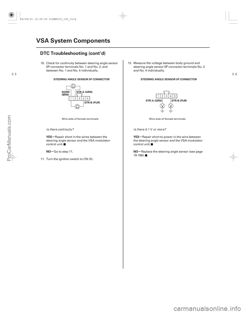
10. Check for continuity between steering angle sensor5P connector terminals No. 1 and No. 2, and
between No. 1 and No. 4 individually.
Repair short in the wires between the
steering angle sensor and the VSA modulator-
control unit.
Go to step 11.
11. Turn the ignition switch to ON (II). 12. Measure the voltage between body ground and
steering angle sensor 5P connector terminals No. 2
and No. 4 individually.
Repair short to power in the wire between
the steering angle sensor and the VSA modulator-
control unit.
Replace the steering angle sensor (see page
19-168).
Wire side of female terminals Wire side of female terminals
I s t her e cont i nui t y ?I s t her e 0.1 V or mor e?
08/08/21 15:05:55 61SNR030_190_0134
ProCarManuals.com
DYNOMITE -2009-
Page 1627 of 2893
�����(�#���������� �����
����������������������)����
�µ
�µ �µ
�µ
DTC 27-23: DTC 27-24:
YES
NO YES
NO
19-13519-135
Steering Angle Sensor Counter
Malf")
�(�#�'��������� �����
�������'���������������)�����(�#�'��������� �����
�������'���������������)����
�µ
�µ �µ
�µ
DTC 27-23: DTC 27-24:
YES
NO YES
NO
19-13519-135
Steering Angle Sensor Counter
Malfunction Steering Angle Sensor Exchange
Malfunction
1. Turn the ignition switch to ON (II).
2. Clear the DTC with the HDS.
3. Turn the ignition switch to LOCK (0), then turn it to
ON (II) again.
4. Turn the steering wheel from lock to lock.
5. Check for DTCs with the HDS.
Replace the steering angle sensor (see page
19-168).
Intermittent failure, the system is OK at this
time. 1. Turn the ignition switch to ON (II), and set the front
wheels to the straight ahead position.
2. Turn the steering wheel one turn to the left. Check the STEERING ANGLE in the VSA DATA LIST with
the HDS.
Intermittent failure, the system is OK at this
time.
Replace the steering angle sensor (see page
19-168).
Is DTC 27-23 indicated? Is t her e about 288 d egr ees t o 432 d egr ees
posi t i v e?
08/08/21 15:05:55 61SNR030_190_0135
ProCarManuals.com
DYNOMITE -2009-
Page 1628 of 2893
����
�µ
�µ
DTC 31-xx :
DTC 32-xx :
DTC 33-xx :
DTC 34-xx :
DTC 35-xx :
DTC 36-xx :
DTC 37-xx :
DTC 38-xx :
Subcode Malfunction Note (DTC) YES
NO
19-136V")
�(�#�'��������� �����
�������'���
�-�-�������)����
�µ
�µ
DTC 31-xx :
DTC 32-xx :
DTC 33-xx :
DTC 34-xx :
DTC 35-xx :
DTC 36-xx :
DTC 37-xx :
DTC 38-xx :
Subcode Malfunction Note (DTC) YES
NO
19-136VSA System Components
DTC Troubleshooting (cont’d)
ABS Right-front Inlet Solenoid
Valve Malfunction
ABS Right-front Outlet Solenoid
Valve Malfunction
ABS Left-front Inlet Solenoid
Valve Malfunction
ABS Left-front Outlet Solenoid
Valve Malfunction
ABS Right-rear Inlet Solenoid
Valve Malfunction
ABS Right-rear Outlet Solenoid
Valve Malfunction
ABS Left-rear Inlet Solenoid
Valve Malfunction
ABS Left-rear Outlet Solenoid
Valve Malfunction
: Any two-character subcode (see table)
01 Solenoid Initial Pulse 31-01, 32-01, 33-01,
34-01, 35-01, 36-01,
37-01, 38-01
21 Solenoid Pulse 31-21, 32-21, 33-21, 34-21, 35-21, 36-21,
37-21, 38-21
22 Solenoid Speculative 31-22, 32-22, 33-22,
34-22, 35-22, 36-22,
37-22, 38-22
23 Solenoid Stuck ON 31-23, 32-23, 33-23,
34-23, 35-23, 36-23,
37-23, 38-23
1. Turn the ignition switch to ON (II).
2. Clear the DTC with the HDS.
3. Turn the ignition switch to LOCK (0), then turn it to ON (II) again. 4. Check for DTCs with the HDS.
Replace the VSA modulator-control unit
(see page 19-171).
Intermittent failure, the system is OK at this
time.
Is DT C 31-xx, 32-xx, 33-xx, 34-xx, 35-xx, 36-xx, 37 -x x , or 38-x x i nd i cat ed ?
08/08/21 15:05:56 61SNR030_190_0136
ProCarManuals.com
DYNOMITE -2009-
Page 1629 of 2893
����
�µ
�µ
�µ
�µ �µ
�µ
DTC 41-21:
DTC 42-21:
DTC 43-21:
DTC 44-21:
DTC Appropriate Wheel
YES
NO
YES
NO YES
NO
19-137
Right-front Wheel Lock
Left-fro")
�(�#�'��������� �����
�������'���
���
�������)����
�µ
�µ
�µ
�µ �µ
�µ
DTC 41-21:
DTC 42-21:
DTC 43-21:
DTC 44-21:
DTC Appropriate Wheel
YES
NO
YES
NO YES
NO
19-137
Right-front Wheel Lock
Left-front Wheel Lock
Right-rear Wheel Lock
Left-rear Wheel Lock
The DTCs may be indicated under these conditions:
The vehicle goes into a spin.
The ABS or VSA continues to operate for a long time.
Snow, dirt, or debris build-up on the wheel speed sensor or magnetic encoder.
Misadjusted brake pedal position switch.
Contaminated brake fluid.
1. Raise the vehicle, and support it with safety stands in the proper locations (see page 1-11).
2. Turn the appropriate wheel by hand.
41-21 Right-front
42-21 Left-front
43-21 Right-rear
44-21 Left-rear
Repair the brake drag.
Go to step 3.
3. Check that the appropriate wheel speed sensor is properly mounted (see page 19-173).
Go to step 4.
Reinstall the wheel speed sensor, and check
the mounting position (see page 19- 173).
4. Turn the ignition switch to ON (II).
5. Clear the DTC with the HDS.
6. Test-drive the vehicle at 10 km/h (7 mph) for 20 seconds or more.
NOTE: Drive the vehicle on a straight section of
road, not on a lift. 7. Check for DTCs with the HDS.
Check for loose terminals in the VSA
modulator-control unit 37P connector. If necessary,
substitute a known-good VSA modulator-control
unit (see page 19-171), and retest.
If any other DTCs are indicated, go to the
indicated DTCs troubleshooting. If DTCs are not
indicated, intermittent failure, the system is OK at
this time.
Is there brake drag?
Is t he w heel speed sensor i nst al l at i on OK ? Is DT C 41-21, 42-21, 43-21, and/ or 44-21
indicated?
08/08/21 15:05:56 61SNR030_190_0137
ProCarManuals.com
DYNOMITE -2009-
Page 1630 of 2893
�����(�#���������� �����
����������
�
���������)����
�µ
�µ �µ
�µ
�µ
�µ
DTC 51-11:
DTC 51-13: DTC 51-12:
YES
NO YES
NO
YES
NO
19-13819-138VSA Syste")
�(�#�'��������� �����
�������'���
�
�
�������)�����(�#�'��������� �����
�������'���
�
���������)����
�µ
�µ �µ
�µ
�µ
�µ
DTC 51-11:
DTC 51-13: DTC 51-12:
YES
NO YES
NO
YES
NO
19-13819-138VSA System Components
DTC Troubleshooting (cont’d)
Motor Lock
Motor Relay OFF Malfunction
Motor Lock Circuit Malfunction
1. Turn the ignition switch to ON (II).
2. Clear the DTC with the HDS.
3. Turn the ignition switch to LOCK (0), then turn it to
ON (II) again.
4. Wait 5 seconds.
5. Operate any one of the four solenoids, as listed, in the VSA FUNCTION TEST five times with the HDS.
-LFT FT SOLENOID
-RT FT SOLENOID
-LFT REAR SOLENOID
-RT REAR SOLENOID
6. Check for DTCs with the HDS.
Replace the VSA modulator-control unit
(see page 19-171).
Intermittent failure, the system is OK at this
time. 1. Turn the ignition switch to ON (II).
2. Clear the DTC with the HDS.
3. Turn the ignition switch to LOCK (0), then turn it to
ON (II) again.
4. Check for DTCs with the HDS.
Go to step 5.
Intermittent failure, the system is OK at this
time. Check for loose terminals at the VSA
modulator-control unit 37P connector. Refer to
intermittent failures troubleshooting (see page
19-98).
5. Turn the ignition switch to LOCK (0).
6. Check the No. 3 (30 A) fuse in the under-hood fuse/ relay box.
Go to step 7.
Reinstall the checked fuse, then go to step 14.
7. Disconnect the VSA modulator-control unit 37P connector (see step 2 on page 19-171).
I s DT C 5 1-11 or 5 1-13 i nd i cat ed ? I s DT C 5 1-12 i nd i cat ed ?
Isthefuseblown?
08/08/21 15:05:56 61SNR030_190_0138
ProCarManuals.com
DYNOMITE -2009-