Page 1355 of 2893
���
17-32EPS Components
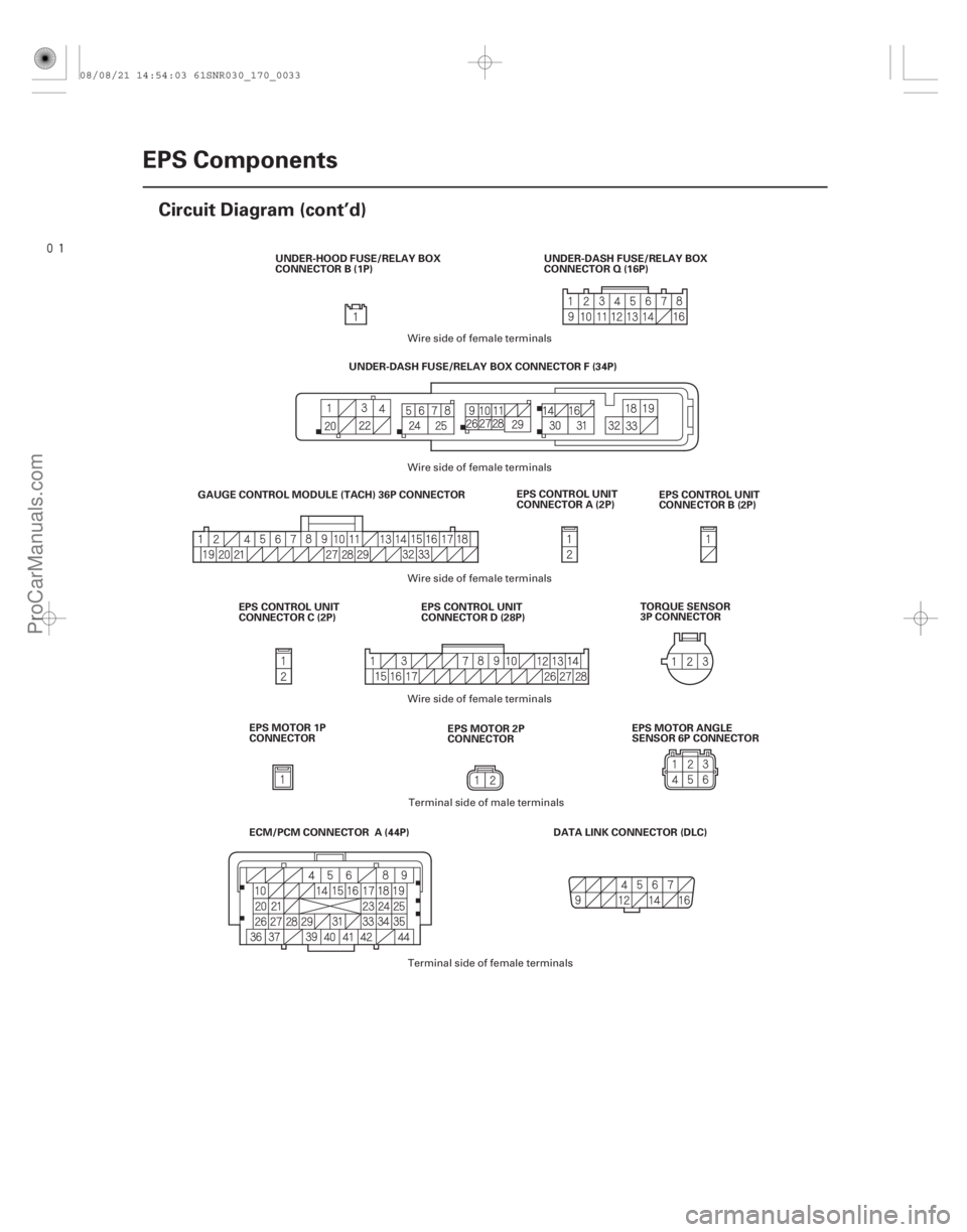
Circuit Diagram (cont’d)
EPS CONTROL UNIT
CONNECTOR A (2P)
EPS CONTROL UNIT
CONNECTOR B (2P)
DATA LINK CONNECTOR (DLC)
GAUGE CONTROL MODULE (TACH) 36P CONNECTOR
UNDER-DASH FUSE/RELAY BOX CONNECTOR F (34P)
EPS CONTROL UNIT
CONNECTOR D (28P)
EPS CONTROL UNIT
CONNECTOR C (2P) TORQUE SENSOR
3P CONNECTOR
UNDER-DASH FUSE/RELAY BOX
CONNECTOR Q (16P)
UNDER-HOOD FUSE/RELAY BOX
CONNECTOR B (1P)
ECM/PCM CONNECTOR A (44P) EPS MOTOR 1P
CONNECTOR EPS MOTOR 2P
CONNECTOREPS MOTOR ANGLE
SENSOR 6P CONNECTOR
Wire side of female terminals
Wire side of female terminals
Terminal side of male terminals
Terminal side of female terminals
Wire side of female terminals
Wire side of female terminals
08/08/21 14:54:03 61SNR030_170_0033
ProCarManuals.com
DYNOMITE -2009-
Page 1362 of 2893
���
�(�#���������� ����������������������������)����
�µ
�µ
�µ
�µ �µ
�µ
�µ
�µ
DTC 32-01:
DTC 32-02:
DTC 35-01:
DTC 35-02:
DTC 35-04:
DTC 35-06:
D")
�(�#�'��������� �������������'�������
�������)���
�(�#�'��������� �������������'���������������)����
�µ
�µ
�µ
�µ �µ
�µ
�µ
�µ
DTC 32-01:
DTC 32-02:
DTC 35-01:
DTC 35-02:
DTC 35-04:
DTC 35-06:
DTC 35-07:
DTC 36-02:
DTC 37-01: DTC 32-07:
YES
NO
YES
NO YES
NO
YES
NO
17-3917-39
EPS Control Unit Internal Circuit
(Current Sensor) (Initial Diagnosis)
EPS Control Unit Internal Circuit
(Current Sensor) (Regular Diagnosis)
EPS Control Unit Internal Circuit
(CPU) (Initial Diagnosis/Regular Diagnosis)
EPS Control Unit Internal Circuit
(EEPROM) (Initial Diagnosis)
EPS Control Unit Internal Circuit
(CPU Communication) (Regular Diagnosis)
EPS Control Unit Internal Circuit
(ITN Communication) (Regular Diagnosis)
EPS Control Unit Internal Circuit
(INHL/INHR Ports) (Initial Diagnosis/Regular
Diagnosis)
EPS Control Unit Internal Circuit
(INH Output Circuit) (Initial Diagnosis)
EPS Control Unit Internal Circuit
(Step-up Circuit) (Initial Diagnosis) EPS Control Unit Internal Circuit
(Current Sensor) (Steering Diagnosis)
1. Turn the ignition switch to ON (II).
2. Clear the DTC with the HDS.
3. Turn the ignition switch to LOCK (0).
4. Start the engine.
Go to step 5.
Check for loose terminals or poor connections.
If the connections are good, the system is OK at
this time.
5. Check for DTCs with the HDS.
Check for loose terminals in the EPS control
unit connectors, and repair if necessary. If no poor
connections are found, replace the EPS control unit
(see page 17-84). Troubleshoot the indicated DTC. If there are
no DTCs, the system is OK at this time. 1. Turn the ignition switch to ON (II).
2. Clear the DTC with the HDS.
3. Turn the ignition switch to LOCK (0).
4. Start the engine.
5. Turn the steering wheel to the right or left, and wait
10 seconds or more.
Go to step 6.
Check for loose terminals or poor connections.
If the connections are good, the system is OK at
this time.
6. Check for DTCs with the HDS.
Check for loose terminals in the EPS control
unit connectors, and repair if necessary. If no poor
connections are found, replace the EPS control unit
(see page 17-84).
Troubleshoot the indicated DTC. If there are
no DTCs, the system is OK at this time.
Does t he E PS i nd i cat or come on?
Is DT C 32-01, 32-02, 35-01, 35-02, 35-04, 35-06,35-07 , 36-02, or 37 -01 ind icated ? Does t he E PS i nd i cat or come on?
Is DTC 32-07 indicated?
08/08/21 14:54:04 61SNR030_170_0040
ProCarManuals.com
DYNOMITE -2009-
Page 1363 of 2893
����
�µ
�µ
�µ
�µ �µ
�µ
DTC 32-08:
DTC 32-09:
YES
NO
YES
NO YES
NO
17-40EPS Components
DTC Troubleshooting (cont’d)
EPS CONTROL UNIT
CONNEC")
����
�(�#�'��������� �������������'���������������)����
�µ
�µ
�µ
�µ �µ
�µ
DTC 32-08:
DTC 32-09:
YES
NO
YES
NO YES
NO
17-40EPS Components
DTC Troubleshooting (cont’d)
EPS CONTROL UNIT
CONNECTOR B
EPS CONTROL UNIT
CONNECTOR C
No. 1
No. 2
No. 1
No. 2
No. 1
No. 1
EPS CONTROL UNIT CONNECTOR B (2P)
H-V (BLU)
H-U (RED) H-W (GRN)
EPS CONTROL UNIT CONNECTOR C (2P)
Current Sensor (Regular
Diagnosis)
Current Sensor (Initial Diagnosis)
1. Turn the ignition switch to ON (II).
2. Clear the DTC with the HDS.
3. Turn the ignition switch to LOCK (0).
4. Start the engine.
5. Turn the steering wheel to the right or left, and wait10 seconds or more.
Go to step 6.
Check for loose terminals or poor connections.
If the connections are good, the system is OK at
this time.
6. Check for DTCs with the HDS.
Go to step 7.
Troubleshoot the indicated DTC. If there are
no DTCs, the system is OK at this time.
7. Turn the ignition switch to LOCK (0). 8. Disconnect EPS control unit connector B (2P) and
connector C (2P).
9. Check for continuity between the following terminals of the EPS control unit connector B (2P)
and connector C (2P).
Check for loose terminals in the EPS control
unit connectors and EPS motor connectors, and
repair if necessary. If no poor connections are
found, replace the EPS control unit (see page 17-84).
Go to step 10.
Wire side of female terminals
Wire side of female terminals
Does t he E PS i nd i cat or come on? I s DT C 32-08 or 32-09 i nd i cat ed ? Is there continuity?
08/08/21 14:54:32 61SNR030_170_0041
ProCarManuals.com
DYNOMITE -2009-
Page 1369 of 2893
�����(�#���������� ����������������
���
�������)����
�µ
�µ
�µ
�µ �µ
�µ
�µ
�µ
DTC 35-03:
DTC 35-05: DTC 51-01:
YES
NO
YES
NO YES
NO
YES
N")
�µ
�µ
�(�#�'��������� �������������'���������������)�����(�#�'��������� �������������'���
���
�������)����
�µ
�µ
�µ
�µ �µ
�µ
�µ
�µ
DTC 35-03:
DTC 35-05: DTC 51-01:
YES
NO
YES
NO YES
NO
YES
NO
17-4617-46EPS Components
DTC Troubleshooting (cont’d)
EPS Control Unit Internal Circuit
(EPS CPU) (Internal Diagnosis)
EPS Control Unit Internal Circuit
(EPS Motor/EPS CPU) (Internal Diagnosis) Low/High Voltage for the Torque
Sensor (VT1 and VT2) (Regular Diagnosis)
1. Turn the ignition switch to ON (II).
2. Clear the DTC with the HDS.
3. Turn the ignition switch to LOCK (0).
4. Turn the ignition switch to ON (II).
Go to step 5.
Check for loose terminals or poor connections.
If the connections are good, the system is OK at
this time.
5. Start the engine.
6. Wait 10 seconds or more.
7. Check for DTCs with the HDS.
Check for loose terminals in the EPS control
unit connectors, and repair if necessary. If no poor
connections are found, replace the EPS control unit
(see page 17-84).
Troubleshoot the indicated DTC. If there are
no DTCs, the system is OK at this time. 1. Turn the ignition switch to LOCK (0).
2. Connect the HDS to the data link connector (DLC).
3. Turn the ignition switch to ON (II).
4. Check the ADVT1 in the DATA LIST with the HDS.
Go to step 5.
Go to step 6.
5. Check the ADVT2 in the DATA LIST with the HDS.
Check for loose terminals or poor
connections. If the connections are good, the
system is OK at this time.
Go to step 6.
6. Turn the ignition switch to LOCK (0).
Does t he E PS i nd i cat or come on?
I s DT C 35 -03 or 35 -05 i nd i cat ed ? Is the v oltage at 0.90 3.55 V ?
Is the voltage at 1.02 3.73 V ?
08/08/21 14:54:34 61SNR030_170_0047
ProCarManuals.com
DYNOMITE -2009-
Page 1371 of 2893

EPS CONTROL UNIT CONNECTOR D (28P)
PVF (BRN) EPS CONTROL UNIT CONNECTOR D (28P)
PVF (BRN)
10. Check for contin")
�������
�µ
�µ �µ
�µ
YES
NO
YES
NO
17-48EPS Components
DTC Troubleshooting (cont’d)
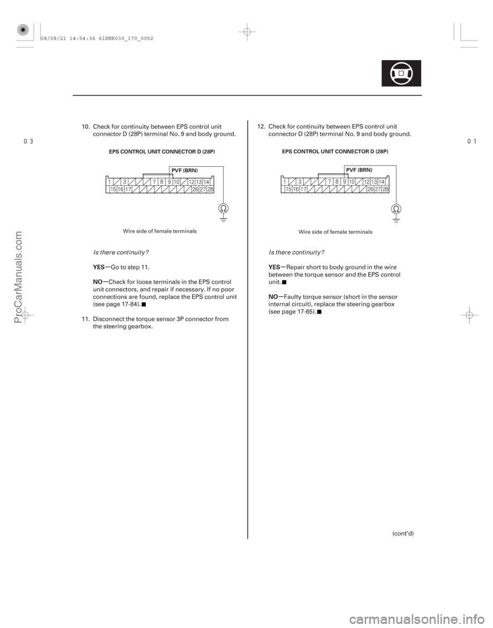
EPS CONTROL UNIT CONNECTOR D (28P)
PVF (BRN) EPS CONTROL UNIT CONNECTOR D (28P)
PVF (BRN)
10. Check for continuity between EPS control unitconnector D (28P) terminal No. 9 and body ground.
Go to step 11.
Check for loose terminals in the EPS control
unit connectors, and repair if necessary. If no poor
connections are found, replace the EPS control unit
(see page 17-84). 11. Disconnect the torque sensor 3P connector from
the steering gearbox.
12. Check for continuity between EPS control unit connector D (28P) terminal No. 9 and body ground.
Repair short to body ground in the wire
between the torque sensor and the EPS control
unit.
Faulty torque sensor (short in the sensor
internal circuit), replace the steering gearbox
(see page 17-65).
Wire side of female terminals
Wire side of female terminals
Is there continuity?Is there continuity?
08/08/21 14:54:34 61SNR030_170_0049
ProCarManuals.com
DYNOMITE -2009-
Page 1372 of 2893

�µ�µ
��������
�µ
�µ �µ
�µ
YES
NO
YES
NO
17-49
TORQUE SENSOR 3P CONNECTOR
VS1 PVF TORQUE SENSOR 3P CONNECTOR
VS2
PVF
13. Disconnect the torque sensor 3P connector from the steering gearbox.
14. On the sensor side, measure the resistance between torque sensor 3P connector terminals
No. 1 and No. 2.
Repair open or short between the PNK and
BLU/RED wires in the torque sensor circuit between
the torque sensor and the EPS control unit.
Faulty torque sensor (short or open in the
internal circuit), replace the steering gearbox
(see page 17-65). 15. Disconnect the torque sensor 3P connector from
the steering gearbox.
16. On the sensor side, measure the resistance between torque sensor 3P connector terminals
No. 2 and No. 3.
Repair open or short between the WHT/GRN
and BLU/RED wires in the torque sensor circuit
between the torque sensor and the EPS control
unit.
Faulty torque sensor (short or open in the
internal circuit), replace the steering gearbox
(see page 17-65).
Terminal side of male terminals Terminal side of male terminals
Is t he r esi st ance bet w een 12 15 ?Is t he r esi st ance bet w een 12 15 ?
08/08/21 14:54:35 61SNR030_170_0050
ProCarManuals.com
DYNOMITE -2009-
Page 1373 of 2893
���
�µ
�µ
�µ
�µ �µ
�µ
�µ
�µ
DTC 51-02:
DTC 51-03:
DTC 51-06:
DTC 51-07:
YES
NO
YES
NO YES
NO
YES
NO
17-50EPS Components
DTC Tro")
�µ
�µ
���
����
�(�#�'��������� �������������'���
�����������)���
�µ
�µ
�µ
�µ �µ
�µ
�µ
�µ
DTC 51-02:
DTC 51-03:
DTC 51-06:
DTC 51-07:
YES
NO
YES
NO YES
NO
YES
NO
17-50EPS Components
DTC Troubleshooting (cont’d)
EPS CONTROL UNIT CONNECTOR D (28P)
PVF (BRN) VS1 (GRN)
EPS CONTROL UNIT CONNECTOR D (28P)
PVF (BRN)
VS2 (LT GRN)
Torque Sensor (VT3 Differential-
amplification Function) (Regular Diagnosis)
Torque Sensor (VT1, VT2 Rapid
Change) (Regular Diagnosis)
Torque Sensor (VT1, VT2
Average) (Regular Diagnosis)
Torque Sensor (VT1, VT2 Initial
Check) (Initial Diagnosis)
1. Turn the ignition switch to ON (II).
2. Clear the DTC with the HDS.
3. Turn the ignition switch to LOCK (0).
4. Start the engine.
Go to step 5.
Check for loose terminals or poor connections.
If the connections are good, the system is OK at
this time.
5. Check for DTCs with the HDS.
Go to step 6.
Troubleshoot the indicated DTC. If there are
no DTCs, the system is OK at this time.
6. Turn the ignition switch to LOCK (0). 7. Disconnect EPS control unit connector D (28P).
8. Measure the resistance between EPS control unit
connector D (28P) terminals No. 9 and No. 10.
Go to step 9.
Go to step 13.
9. Measure the resistance between EPS control unit connector D (28P) terminals No. 8 and No. 9.
Go to step 10.
Go to step 15.
Wire side of female terminals
Wire side of female terminals
Does t he E PS i nd i cat or come on?
I s DT C 5 1-02, 5 1-03, 5 1-06, or 5 1-07 i nd i cat ed ? Is t he r esi st ance bet w een 12 15 ?
Is t he r esi st ance bet w een 12 15 ?
08/08/21 14:54:35 61SNR030_170_0051
ProCarManuals.com
DYNOMITE -2009-
Page 1374 of 2893
�������
�µ
�µ �µ
�µ
YES
NO
YES
NO
17-51
EPS CONTROL UNIT CONNECTOR D (28P)
PVF (BRN) EPS CONTROL UNIT CONNECTOR D (28P)
PVF (BRN)
10. Check for continuity between EPS control unitconnector D (28P) terminal No. 9 and body ground.
Go to step 11.
Check for loose terminals in the EPS control
unit connectors, and repair if necessary. If no poor
connections are found, replace the EPS control unit
(see page 17-84).
11. Disconnect the torque sensor 3P connector from the steering gearbox. 12. Check for continuity between EPS control unit
connector D (28P) terminal No. 9 and body ground.
Repair short to body ground in the wire
between the torque sensor and the EPS control
unit.
Faulty torque sensor (short in the sensor
internal circuit), replace the steering gearbox
(see page 17-65).
(cont’d)
Wire side of female terminals Wire side of female terminals
I s t her e cont i nui t y ?I s t her e cont i nui t y ?
08/08/21 14:54:36 61SNR030_170_0052
ProCarManuals.com
DYNOMITE -2009-