Page 1375 of 2893

TORQUE SENSOR 3P CONNECTOR
VS1 PVF TORQUE SENSOR 3P CONNECTOR
VS2
PVF
13. Disconnect the torque sensor")
�µ�µ
��������
�µ
�µ �µ
�µ
YES
NO
YES
NO
17-52EPS Components
DTC Troubleshooting (cont’d)
TORQUE SENSOR 3P CONNECTOR
VS1 PVF TORQUE SENSOR 3P CONNECTOR
VS2
PVF
13. Disconnect the torque sensor 3P connector from the steering gearbox.
14. On the sensor side, measure the resistance between torque sensor 3P connector terminals
No. 1 and No. 2.
Repair open or short between the PNK and
BLU/RED wires in the torque sensor circuit between
the torque sensor and the EPS control unit.
Faulty torque sensor (short or open in the
internal circuit), replace the steering gearbox
(see page 17-65). 15. Disconnect the torque sensor 3P connector from
the steering gearbox.
16. On the sensor side, measure the resistance between torque sensor 3P connector terminals
No. 2 and No. 3.
Repair open or short between the BLU/RED
and WHT/GRN wires in the torque sensor circuit
between the torque sensor and the EPS control
unit.
Faulty torque sensor (short or open in the
internal circuit), replace the steering gearbox
(see page 17-65).
Terminal side of male terminals Terminal side of male terminals
Is t he r esi st ance bet w een 12 15 ?Is t he r esi st ance bet w een 12 15 ?
08/08/21 14:54:36 61SNR030_170_0053
ProCarManuals.com
DYNOMITE -2009-
Page 1378 of 2893
����
�µ
�µ �µ
�µ
�µ
�µ
YES
NO
YES
NO
YES
NO
DTC 71-01:
DTC 71-02:
DTC 71-03:
DTC 71-05:
DTC 71-06:
17-5517-55
No. 1
No. 2
No. 1
No. 2
H-W (R")
�����
�(�#�'��������� �������������'���
���
�������)����
�µ
�µ �µ
�µ
�µ
�µ
YES
NO
YES
NO
YES
NO
DTC 71-01:
DTC 71-02:
DTC 71-03:
DTC 71-05:
DTC 71-06:
17-5517-55
No. 1
No. 2
No. 1
No. 2
H-W (RED)
H-U (BLK)
H-V (WHT)
EPS MOTOR
1P CONNECTOR
EPS MOTOR
2P CONNECTOR
No. 1
No. 1
EPS MOTOR 2P CONNECTOR
EPS MOTOR 1P CONNECTOR
13. Disconnect the EPS motor 1P connector and the
EPS motor 2P connector.
14. On the EPS motor side, check for continuity between the following terminals of the EPS motor
1P and the EPS motor 2P connector.
Repair open in the wire between the EPS
control unit and the EPS motor.
Open in the EPS motor wire, or EPS motor
internal circuit, replace the EPS motor (see page
17-63). 1. Turn the ignition switch to ON (II).
2. Clear the DTC with the HDS.
3. Turn the ignition switch to LOCK (0).
4. Start the engine.
5. Turn the steering wheel to the right or left, and wait
10 seconds or more.
Go to step 6.
Check for loose terminals or poor connections.
If the connections are good, the system is OK at
this time.
6. Check for DTCs with the HDS.
Go to step 7.
Troubleshoot the indicated DTC. If there are
no DTCs, the system is OK at this time.
7. Turn the ignition switch to LOCK (0).
8. Disconnect EPS control unit connector D (28P).
(cont’d)EPS Motor Angle Sensor (SIN/
COS Signals) (Steering Diagnosis)
EPS Motor Angle Sensor (Neutral
Position Learning of SIN/COS) (Initial
Diagnosis)
EPS Motor Angle Sensor (SIN/
COS Signals) (Steering Diagnosis)
EPS Motor Angle Sensor (SIN/
COS Signals Charging Amount) (Steering
Diagnosis)
EPS Motor Angle Sensor (Neutral
Position of SIN/COS) (Initial Diagnosis)
Terminal side of male terminal
Terminal side of male terminals
Is there continuity? Does t he E PS i nd i cat or come on?
Is DT C 7 1-01, 7 1-02, 7 1-03, 7 1-05 or 7 1-06indicated?
08/08/21 14:54:37 61SNR030_170_0056
ProCarManuals.com
DYNOMITE -2009-
Page 1379 of 2893

No. 27 (R2)
No. 13 (R1)
No. 12 (S1)
No. 14 (S2) No. 26 (S3)
No. 28 (S4)
EPS CONTROL UNIT CONNECTOR")
�µ
�µ�µ
���
����
�µ
�µ �µ
�µ
YES
NO YES
NO
17-56EPS Components
DTC Troubleshooting (cont’d)
No. 27 (R2)
No. 13 (R1)
No. 12 (S1)
No. 14 (S2) No. 26 (S3)
No. 28 (S4)
EPS CONTROL UNIT CONNECTOR D (28P)
EPS CONTROL UNIT CONNECTOR D (28P) S1 (PNK)
S3 (BRN) S4 (BLU)
S2 (BRN)
R1 (BLU)
R2 (PNK) EPS CONTROL UNIT CONNECTOR D (28P)
S3 (BRN)R2 (PNK) S4 (BLU) S2 (BRN)
R1 (BLU)
S1 (PNK)
9. Measure the resistance between the following
terminals of EPS control unit connector D (28P).
Go to step 10.
Go to step 13. 10. Check for continuity between body ground and EPS
control unit connector D (28P) terminal No. 12,
terminal No. 13, terminal No. 14, terminal No. 26,
terminal No. 27, and terminal No. 28 individually.
Go to step 11.
Check for loose terminals in the EPS control
unit connectors, and repair if necessary. If no poor
connections are found, replace the EPS control unit
(see page 17-84).
11. Disconnect the EPS motor angle sensor 6P connector.
Wire side of female terminals
Wire side of female terminals
Is t he r esi st ance bet w een R1-R2 13 25 , S1-S326 49 , and S2-S4 26 49 ? I s t her e cont i nui t y ?
08/08/21 14:54:37 61SNR030_170_0057
ProCarManuals.com
DYNOMITE -2009-
Page 1380 of 2893
R2
(GRN)S4 (RED) S2 (BLK)
R1 (BRN)
S1 (YEL) No. 5 (R2)
No. 2 (R1)
No. 1 (S1)
No. 3 (S2) No. 4 (S3)
N")
�µ
�µ�µ
���
����
�µ
�µ �µ
�µ
YES
NO
YES
NO
17-57
EPS MOTOR ANGLE SENSOR 6P CONNECTOR
S3
(BLU)R2
(GRN)S4 (RED) S2 (BLK)
R1 (BRN)
S1 (YEL) No. 5 (R2)
No. 2 (R1)
No. 1 (S1)
No. 3 (S2) No. 4 (S3)
No. 6 (S4)
EPS MOTOR ANGLE SENSOR 6P CONNECTOR
EPS MOTOR ANGLE SENSOR 6P CONNECTOR S1 (YEL)
S3 (BLU) R1 (BRN)
S2 (BLK)
S4 (RED)
R2 (GRN)
12. On the sensor side, check for continuity between body ground and EPS motor angle sensor 6P
connector terminal No. 1, terminal No. 2, terminal
No.3,terminalNo.4,terminalNo.5,andterminal
No. 6 individually.
Faulty EPS motor angle sensor (internal
failure), or short to body ground in the wire (sensor
side), replace the EPS motor (see page 17-63).
Repair short to body ground in the wire
between the EPS motor angle sensor 6P connector
and the EPS control unit. 13. Disconnect the EPS motor angle sensor 6P
connector.
14. On the sensor side, measure the resistance between the following terminals of the EPS motor
angle sensor 6P connector.
Open, or short to body ground in the wire
between the EPS motor angle sensor 6P connector
and the EPS control unit.
Faulty EPS motor angle sensor (internal
failure), or short to body ground in the wire (sensor
side), replace the EPS motor (see page 17-63).
Terminal side of male terminals
Terminal side of male terminals
Is there continuity?Is t he r esi st ance bet w een R1-R2 13 25 , S1-S326 49 , and S2-S4 26 49 ?
08/08/21 14:54:38 61SNR030_170_0058
ProCarManuals.com
DYNOMITE -2009-
Page 1381 of 2893
����
�µ
�µ
�µ
�µ �µ
�µ
�µ
�µ
DTC 71-04:
YES
NO
YES
NO YES
NO
YES
NO
17-58EPS Components
DTC Troubleshooting (cont’d)
EPS CONTROL U")
�µ
���
����
�(�#�'��������� �������������'���
�����������)����
�µ
�µ
�µ
�µ �µ
�µ
�µ
�µ
DTC 71-04:
YES
NO
YES
NO YES
NO
YES
NO
17-58EPS Components
DTC Troubleshooting (cont’d)
EPS CONTROL UNIT CONNECTOR D (28P)
R1 (BLU)
R2 (PNK)
EPS CONTROL UNIT CONNECTOR D (28P) R1 (BLU)
R2 (PNK)
EPS Motor Angle Sensor (Check
Signals) (Regular Diagnosis)
1. Turn the ignition switch to ON (II).
2. Clear the DTC with the HDS.
3. Turn the ignition switch to LOCK (0).
4. Start the engine.
5. Turn the steering wheel to the right or left, and wait
10 seconds or more.
Go to step 6.
Check for loose terminals or poor connections.
If the connections are good, the system is OK at
this time.
6. Check for DTCs with the HDS.
Go to step 7.
Troubleshoot the indicated DTC. If there are
no DTCs, the system is OK at this time.
7. Turn the ignition switch to LOCK (0).
8. Disconnect the EPS control unit connector D (28P). 9. Measure the resistance between the EPS control
unit connector D (28P) terminal No. 13 and No. 27.
Go to step 10.
Go to step 13.
10. Check for continuity between body ground and the EPS control unit connector D (28P) terminal No. 13
and the terminal No. 27 individually.
Go to step 11.
Check for loose terminals in the EPS control
unit connectors, and repair if necessary. If no poor
connections are found, replace the EPS control unit
(see page 17-84).
Wire side of female terminals
Wire side of female terminalsDoes t he E PS i nd i cat or come on?
Is DTC 71-04 indicated? Is t he r esi st ance bet w een 13 25 ?
Is there continuity?
08/08/21 14:54:38 61SNR030_170_0059
ProCarManuals.com
DYNOMITE -2009-
Page 1382 of 2893

R1 (BRN)
EPS MOTOR ANGLE SENSOR 6P CONNECTOR
R2 (GRN)
R1 (BRN)
11. Disconnect the EPS motor angle sensor 6")
�µ
���
����
�µ
�µ �µ
�µ
YES
NO YES
NO
17-59
EPS MOTOR ANGLE SENSOR 6P CONNECTOR
R2 (GRN)
R1 (BRN)
EPS MOTOR ANGLE SENSOR 6P CONNECTOR
R2 (GRN)
R1 (BRN)
11. Disconnect the EPS motor angle sensor 6P
connector.
12. On the sensor side check for continuity between body ground and EPS motor angle sensor 6P
connector terminal No. 2 and the terminal No. 5
individually.
Faulty EPS motor angle sensor (internal
failure), or short to body ground in the wire (sensor
side), replace the EPS motor (see page 17-63).
Repair short to body ground in the wire
between the EPS motor angle sensor 6P connector
and the EPS control unit. 13. Disconnect the EPS motor angle sensor 6P
connector.
14. On the sensor side measure the resistance between the EPS motor angle sensor 6P connector terminals
No. 2 and No. 5.
Open, or short to body ground in the wire
between the EPS motor angle sensor 6P connector
and EPS control unit.
Faulty EPS motor angle sensor (internal
failure), or short to body ground in the wire (sensor
side), replace the EPS motor (see page 17-63).
Terminal side of male terminals Terminal side of male terminals
Is there continuity?
Is t he r esi st ance bet w een 13 25?
08/08/21 14:54:39 61SNR030_170_0060
ProCarManuals.com
DYNOMITE -2009-
Page 1386 of 2893
���
����
�(�#�'�����������
���
�����������
����� �����)����
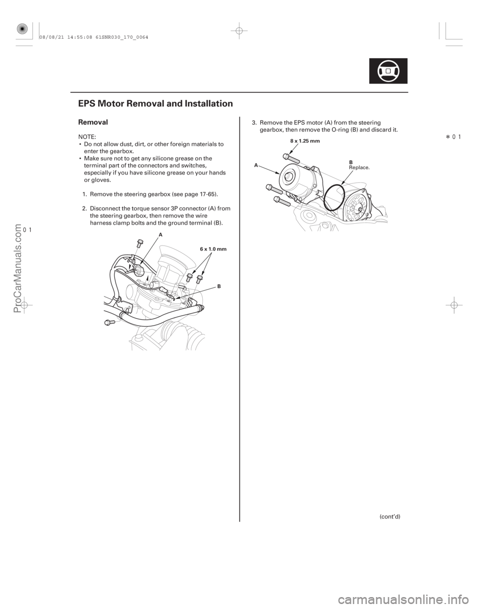
Removal
17-63
EPS Motor Removal and Installation
A B
6x1.0mm A
B
8x1.25mm
NOTE:
Do not allow dust, dirt, or other foreign materials to enter the gearbox.
Make sure not to get any silicone grease on the terminal part of the connectors and switches,
especially if you have silicone grease on your hands
or gloves.
1. Remove the steering gearbox (see page 17-65).
2. Disconnect the torque sensor 3P connector (A) from the steering gearbox, then remove the wire
harness clamp bolts and the ground terminal (B). 3. Remove the EPS motor (A) from the steering
gearbox, then remove the O-ring (B) and discard it.
(cont’d)
Replace.
08/08/21 14:55:08 61SNR030_170_0064
ProCarManuals.com
DYNOMITE -2009-
Page 1387 of 2893

C
B
E
8x1.25mm
20 N·m
(2.0 kgf·m,
14 lbf·ft)
A
D A
6x1.0mm
9.8 N·m
(1.0 kgf·m,
7.2 lbf·ft)
B
1. Clean the")
��������
Installation
17-64EPS Components
EPS Motor Removal and Installation (cont’d)
C
B
E
8x1.25mm
20 N·m
(2.0 kgf·m,
14 lbf·ft)
A
D A
6x1.0mm
9.8 N·m
(1.0 kgf·m,
7.2 lbf·ft)
B
1. Clean the mating surface of the EPS motor (A) andthe steering gearbox.
2. Apply a thin coat of silicone grease to the new O-ring (B), and carefully fit it on the EPS motor.
3. Apply steering grease into the EPS motor shaft (C).
4. Set the EPS motor on the gearbox by engaging the EPS motor shaft and the worm shaft (D).
5. Turn the EPS motor two or three times to the right and left about 45 degrees. Make sure the EPS
motor is evenly seated on the steering gearbox,
and that the O-ring is not pinched between the
mating surfaces.
6. Loosely install the motor mount bolts(E), then turn the steering shaft two or three times to the right
and left about 45 degrees.
7. Tighten the motor mount bolts to the specified torque. 8. Connect the torque sensor 3P connector (A) to the
steering gearbox, then install the wire harness
clamp bolts and the ground terminal (B).
9. Finish the installation, and note these items: Make sure the torque sensor 3P connector isproperly connected.
Make sure the EPS motor and the EPS wires are not caught or pinched by any parts.
10. Install the steering gearbox (see page 17-72).
Replace.
08/08/21 14:55:09 61SNR030_170_0065
ProCarManuals.com
DYNOMITE -2009-