Page 1427 of 2893
 and the snap ring (B)
from the knuckle (C).")
�
��
�
�������
18-19
5x0.8mmA
B C
A 07749-0010000
B Press
07746-0010500 B
E
Press
07965-SD90100
A C D
07GAD-SD40101 INSIDE
3. Remove the splash guard (A) and the snap ring (B)
from the knuckle (C).
4. Press the wheel bearing (A) out of the knuckle (B) using the attachment, the driver handle, and a
press. 5. Wash the knuckle and the hub thoroughly in high
flash point solvent before reassembly.
6. Press a new wheel bearing (A) into the knuckle (B) using the old bearing (C), a steel plate (D), the
attachment, the support base, and a press.
NOTE: Install the wheel bearing with the wheel speed sensor magnetic encoder (E) (brown color)
toward the inside of the knuckle.
Remove any oil, grease, dust, metal debris, and other foreign material from the encoder surface.
Keep all magnetic tools away from the encoder surface.
Be careful not to damage the encoder surface when you insert the wheel bearing.
(cont’d)
08/08/21 14:56:52 61SNR030_180_0019
ProCarManuals.com
DYNOMITE -2009-
Page 1436 of 2893
����
Removal
18-26 Front Suspension
Damper/Spring Removal and Installation
A
B
8x1.25mm
A
14x1.5mm
B A
B
C
10x1.25mm
A
1. Turn the igni")
����
���
����
����
�(�#�'�����������������������
���
���
� �����)����
Removal
18-26 Front Suspension
Damper/Spring Removal and Installation
A
B
8x1.25mm
A
14x1.5mm
B A
B
C
10x1.25mm
A
1. Turn the ignition switch to ON (II), then turn on thewindshield wipers. Turn the ignition switch to
LOCK (0) when the wipers are near the A-pillars.
2. Raise the front of the vehicle, and support it with safety stands in the proper locations (see page
1-11).
3. Remove the front wheel.
4. Remove the wheel speed sensor harness clip (A) and the brake hose bracket (B) from the damper. Do
not disconnect the wheel speed sensor connector.
5. Remove the damper pinch bolts (A) and the self- locking nuts (B) from the damper.
NOTE: Do not allow the knuckle to rotate too far
outward. This may allow the driveshaft inboard
joint come apart. 6. Remove the service cap (A) and the lid (B).
7. Remove the three flange nuts (C) from top of the
damper.
8. Remove the damper/spring (A). NOTE: The left and right damper springs are different. Mark the springs L and R before you continue.
Be careful not to damage the body.
Replace.
Replace. Replace.
08/08/21 14:57:38 61SNR030_180_0026
ProCarManuals.com
DYNOMITE -2009-
Page 1437 of 2893

’06-08 models type S model:
10x1.25mm
59N·m(6.0kgf·m,43lbf·ft)
�")
�
��
����
����
�
��
Installation
18-27
FRONT
A
B
C
A
’06-08 models except Type S model:
10x1.25mm
44N·m(4.5kgf·m,33lbf·ft)
’06-08 models type S model:
10x1.25mm
59N·m(6.0kgf·m,43lbf·ft)
’09 model:
10x1.25mm
59N·m(6.0kgf·m,43lbf·ft)
A
14x1.5mm
90 N·m
(9.2 kgf·m,
67 lbf·ft)
C
B
A
B
C
8x1.25mm
22 N·m
(2.2 kgf·m, 16 lbf·ft)1. Install the damper/spring (A) onto the frame. Note
the direction of the damper mounting base as
shown.
NOTE: Be careful not to damage the body.
2. Loosely install the new flange nuts (A). NOTE: Install the service cap (B) and the lid (C) after
tightening the flange nuts to the specified torque
value. 3. Loosely install the new damper pinch bolts (A) and
the new self-locking nuts (B) to the damper (C).
4. Raise the front suspension with a floor jack to load the suspension with the vehicle’s weight.
5. Tighten the flange nuts on top of the damper to the specified torque value.
6. Tighten the damper pinch bolts to the specified torque value.
7. Install the wheel speed sensor harness clip (A) and the brake hose bracket (B) to the damper (C).
8. Install the service cap and the lid.
9. Clean the mating surfaces of the brake disc and the inside of the wheel, then install the front wheel.
10. Check the wheel alignment, and adjust it if necessary (see page 18-5).
11. Turn the ignition switch to ON (II), then turn the windshield wipers to the default positions, and turn
the ignition switch to LOCK (0).
Replace.
Replace.
Replace.
Replace.
Replace.
08/08/21 14:57:39 61SNR030_180_0027
ProCarManuals.com
DYNOMITE -2009-
Page 1443 of 2893

A
6x1.0mm
9.8 N·m
(1.0 kgf·m,
7.2 lbf·ft) D
8x1.25mm
22 N·m
(2.2 kgf·m, 16 lbf·ft)
8x1.25mm
22 N·m
(2.2 kg")
����
����� ����
Knuckle Replacement
18-33
6x1.0mm
9.8 N·m
(1.0 kgf·m,
7.2 lbf·ft)
A
6x1.0mm
9.8 N·m
(1.0 kgf·m,
7.2 lbf·ft) D
8x1.25mm
22 N·m
(2.2 kgf·m, 16 lbf·ft)
8x1.25mm
22 N·m
(2.2 kgf·m, 16 lbf·ft)
AB
C
(Multipurpose) 6x1.0mm
9.8 N·m
(1.0 kgf·m,
7.2 lbf·ft)
A
12x1.25mm
108 N·m
(11.0 kgf·m,
79.6 lbf·ft)
B
C
1. Remove the hub bearing unit.
2. Remove the splash guard (A).
3. Remove the wheel speed sensor (A), and the brake hose mounting bracket (B) from the knuckle (C). Do
not disconnect the wheel speed sensor connector.
NOTE: Apply multipurpose grease to the mating surfaces on the knuckle and the O-ring during
reassembly.
To prevent O-ring damage, the wheel speed sensor must be installed with the guide pin tool
during reassembly (see step 5 on page 19-175).
4. Remove the parking brake cable mounting bolt (D) from the Knuckle. 5. Place a floor jack under the tra
iling arm to support
it.
NOTE: Do not place the jack against the plate
section of the lower arm. Be careful not to damage
any suspension components.
6. Remove the upper arm mounting bolt (A), and disconnect the upper arm (B) from the knuckle.
NOTE: Use the new upper arm mounting bolt
during reassembly.
7. Remove the rear knuckle upper bracket (C).
(cont’d)
Replace.
08/08/21 14:57:42 61SNR030_180_0033
ProCarManuals.com
DYNOMITE -2009-
Page 1455 of 2893
����
��������
����
Removal
18-43
A
B
6x1.0mm
C
8x1.25mm
AC
12x1.25mm
D
B B
C A
12x1.25mm
A
12x1.25mm
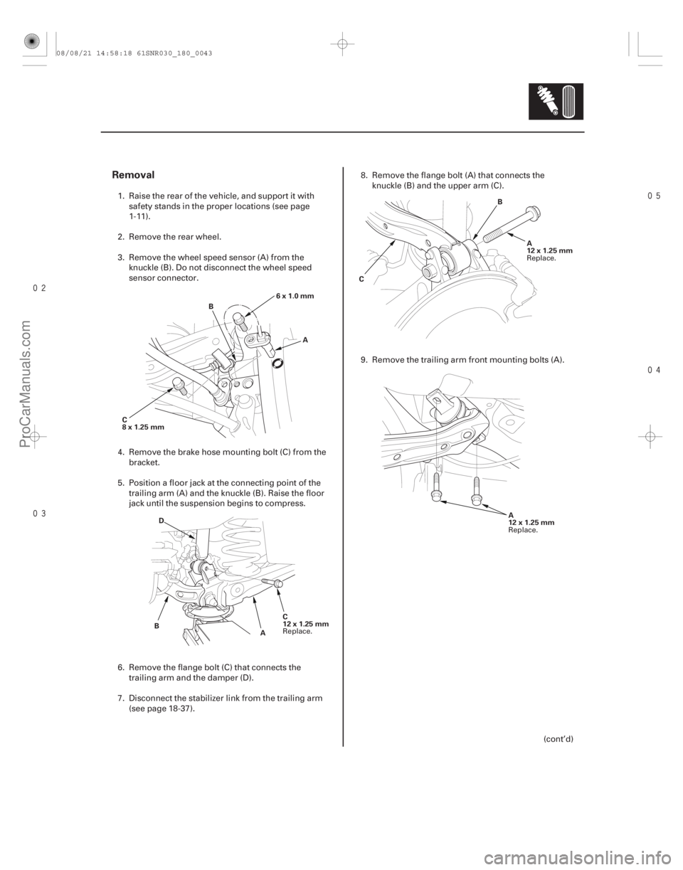
1. Raise the rear of the vehicle, and support it with safety stands in the proper locations (see page
1-11).
2. Remove the rear wheel.
3. Remove the wheel speed sensor (A) from the knuckle (B). Do not disconnect the wheel speed
sensor connector.
4. Remove the brake hose mounting bolt (C) from the bracket.
5. Position a floor jack at the connecting point of the trailing arm (A) and the knuckle (B). Raise the floor
jack until the suspension begins to compress.
6. Remove the flange bolt (C) that connects the trailing arm and the damper (D).
7. Disconnect the stab ilizer link from the trailing arm
(see page 18-37). 8. Remove the flange bolt (A) that connects the
knuckle (B) and the upper arm (C).
9. Remove the trailing arm front m ounting bolts (A).
(cont’d)
Replace. Replace.
Replace.
08/08/21 14:58:18 61SNR030_180_0043
ProCarManuals.com
DYNOMITE -2009-
Page 1458 of 2893
�����
18-46Rear Suspension
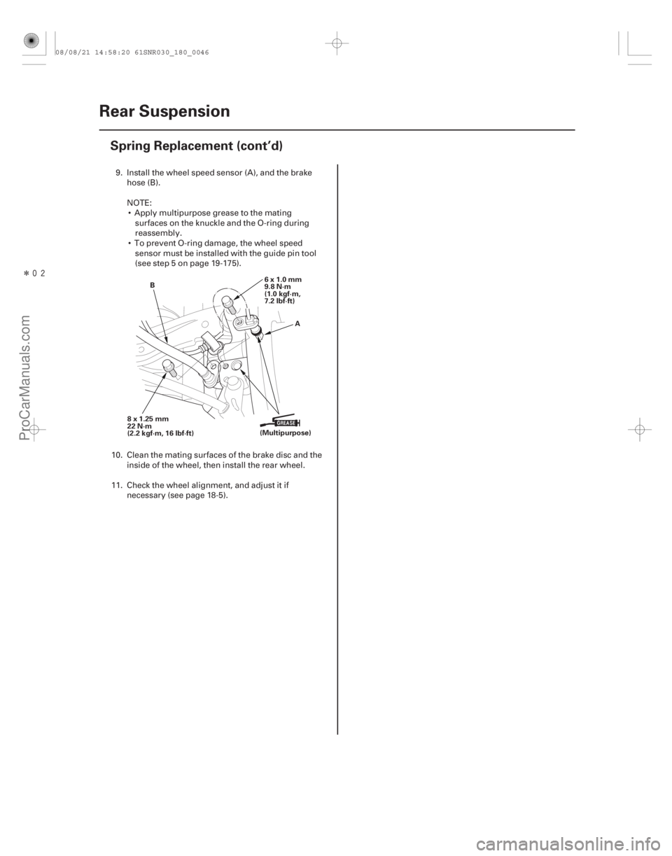
Spring Replacement (cont’d)
A
B
6x1.0mm
9.8 N·m
(1.0 kgf·m,
7.2 lbf·ft)
8x1.25mm
22 N·m
(2.2 kgf·m, 16 lbf·ft) (Multipurpose)
9. Install the wheel speed sensor (A), and the brake
hose (B).
NOTE: Apply multipurpose grease to the mating surfaces on the knuckle and the O-ring during
reassembly.
To prevent O-ring damage, the wheel speed sensor must be installed with the guide pin tool
(see step 5 on page 19-175).
10. Clean the mating surfaces of the brake disc and the inside of the wheel, then install the rear wheel.
11. Check the wheel alignment, and adjust it if necessary (see page 18-5).
08/08/21 14:58:20 61SNR030_180_0046
ProCarManuals.com
DYNOMITE -2009-
Page 1459 of 2893
�
��
Suspension
............................
............................
Front and Rear Suspension . 18-2
............................................
..")
�(�#�'�������������������������
�����
�/�����)�
��
Suspension
............................
............................
Front and Rear Suspension . 18-2
............................................
............................................
Front Suspension . 18-14
..............................................
..............................................
Rear Suspension . 18-31
TPMS (Tire Pressure Monitoring System) (’08-09 Models)
........................................
........................................
...................................
....................................... ..............................
.....................................................
............................................................ ....................................................................................................................................................
........................................
........................................
...................................
....................................... ..............................
.....................................................
............................................................ ....................................................................................................................................................
Component Location Index . 18-48
General Troubleshooting Information . 18-49
Memorizing the Tire Pressure Sensor ID . 18-52
Tire Pressure Sensor Location . 18-53
DTC Troubleshooting Index . 18-55
Symptom Troubleshooting Index . 18-56
System Description . 18-57
Circuit Diagram . 18-61
DTC Troubleshooting . 18-63
Symptom Troubleshooting . 18-71
TPMS Control Unit Replacement . 18-75
Tire Pressure Sensor Replacement . 18-76
08/08/21 14:58:20 61SNR030_180_0047
ProCarManuals.com
DYNOMITE -2009-
Page 1460 of 2893
����
�(�#�'���������������
�����
�����������������)����
18-48TPMS
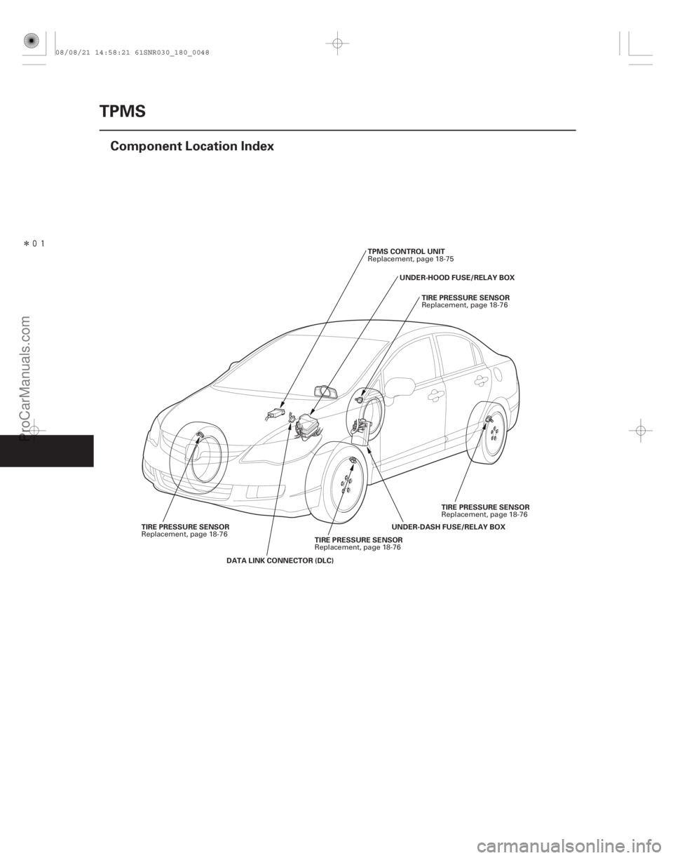
Component Location Index
TIRE PRESSURE SENSOR
DATA LINK CONNECTOR (DLC) UNDER-DASH FUSE/RELAY BOX
TPMS CONTROL UNIT
TIRE PRESSURE SENSOR
TIRE PRESSURE SENSOR
TIRE PRESSURE SENSOR UNDER-HOOD FUSE/RELAY BOX
Replacement, page 18-76 Replacement, page 18-75
Replacement, page 18-76
Replacement, page 18-76
Replacement, page 18-76
08/08/21 14:58:21 61SNR030_180_0048
ProCarManuals.com
DYNOMITE -2009-