Page 1145 of 2893
�
��
14-229
ATF Temperature Sensor Test/Replacement
A
18x1.5mm
49 N·m
(5.0 kgf·m, 36 lbf·ft) B A
B
6x1.0mm
12 N·m (1.2 kgf·m, 8.7")
����
�����
����
�(�#�'�������
���
�����
�����
�������
�������)�
��
14-229
ATF Temperature Sensor Test/Replacement
A
18x1.5mm
49 N·m
(5.0 kgf·m, 36 lbf·ft) B A
B
6x1.0mm
12 N·m (1.2 kgf·m, 8.7 lbf·ft)
B
C
6x1.0mm
12 N·m
(1.2 kgf·m, 8.7 lbf·ft)
1. Raise the vehicle on a lift, or apply the parkingbrake, block the rear wheels, and raise the front of
the vehicle. Make sure it is securely supported.
2. Remove the splash shield.
3. Remove the drain plug (A), and drain the automatic transmission fluid (ATF).
4. Reinstall the drain plug with a new sealing washer (B).
5. Do the battery removal procedure (see page 22-69).
6. Remove the intake air duct (see page 11-348) and the air cleaner assembly (see page 11-345).
7. Remove the battery tray, the battery base, and the resonator. 8. Remove the shift solenoid valve cover (A), the
dowel pins (B), and the gasket (C).
9. Disconnect the shift solenoid wire harness connector, and remove it from the transmission
housing.
(cont’d)
Replace. Replace.
08/08/21 14:46:51 61SNR030_140_0231
ProCarManuals.com
DYNOMITE -2009-
Page 1196 of 2893
����
�Ó
�Ú
�Ø �µ
14-279
Circuit Diagram
22
36 444342 27 28
3033 34 35
32 25
20 21 22 16 1817
13 14 15
12
11 789
31
3123
31
456
1514
2120 25
24")
����
�(�#�'�������
���
���������������������������)����
�Ó
�Ú
�Ø �µ
14-279
Circuit Diagram
22
36 444342 27 28
3033 34 35
32 25
20 21 22 16 1817
13 14 15
12
11 789
31
3123
31
456
1514
2120 25
24
34
33
292827
42 44
40
37
36 31
123456 9
87
11 12 151413 17 1816
32
29
30
42 43 44
40
39
36
18
17
16 19
3598
10 2120
27
2
26 29 40
4
23 24
41 23
41
39
10
26
G601
4 3
DN
R
P ST
S RVS
FWD
BKSW LT GRN
LT GRNWHT
No. 12 (15 A)
YEL
BRN
PG SG 16
15
BLK A40
BKSW
WHT/BLK BLK LT BLU
BLK
C(44P)
B(44P)
A(44P)
Terminal side of female terminals
G503
BLK A36
A37
WHT
RED
RED
WHT
1
19 CANH
CANL
17
P
R
N
D
S
GAUGE CONTROL MODULE (TACH)
2 1 3 4 1
3827
65 41017
6
549 38 10
KEYSW KEYSOL
G504
BLU
PNK
PUR
BLK P-PIN
ATPPBLU/BLK 5 4 6 2 1
3
GRY PUR
LT BLU
A24
VCC5
APSB A18
A34
SG5
SG4
A35
A17
APSA VCC4 A25
BLUYEL
BRN
PG1
PG2
LG1
LG2
C40 B1
C44 B36
BRN/YEL
BRN/YEL
G101 PNK
BLK
B13 BLK/GRN
BRN
C36
IG1
12 V
No. 2 (15 A)
UNDER-DASH FUSE/RELAY BOX
No. 10 (7. 5 A)
BLU/WHT
RED/BLK
WHT ORN
SLS
A27
RED
BLK BAT
IG1
IGNITION SWITCH
5V
BLK
BLU/WHT
TRANSMISSION RANGE SWITCH
B22
ATPRVS
ATPFWD
ATPP
ATPR ATPN ATPD
ATPS
YEL/RED
B28
G101
B12
B21
BLU
PNK
RED/BLK
WHT
BLK/BLU
B14 B15
WHT/RED
BLU/BLK YEL/GRN
RED
BLU/YEL
1
2 YEL
PNK
UNDER-HOOD FUSE/RELAY BOX
No. 2 (IG) (50 A)
No. 1 (100 A)
BATTERY
STARTER
CUT
RELAY
SHIFT
LOCK
SOLENOID BRAKE
PEDAL
POSITION
SWITCH
ACCELERATOR
PEDAL
POSITION
SENSOR
KEY
INTERLOCK
SOLENOID IGNITION
KEY
SWITCH UNDER-DASH
FUSE/RELAY BOX
No.35(7.5A)
F-CAN
TRANSCEIVER
CPU A/T
GEAR
POSITION
INDICATOR
DRIVER
CIRCUIT
PARK PIN
SWITCH DASH-LIGHT
BRIGHTNESS
CONTROL
CIRCUIT
POWERTRAIN CONTROL
MODULE (PCM)
MULTIPLEX
INTEGRATED
CONTROL
UNIT (MICU)
SHIFT
INDICATOR
RED/WHT
GRN
G504
BLK/RED* BLK* *1: ’06 model
*2: ’07 09 models
BLK PCM Connector Terminal Locations GND
1
2
08/08/21 14:50:06 61SNR030_140_0281
ProCarManuals.com
DYNOMITE -2009-
Page 1399 of 2893

A
B
C
12x1.25mm
59 N·m
(6.0 kgf·m, 43 lbf·ft)
D
12x1.25mm
59 N·m
(6.0 kgf·m, 43 lbf·ft) B
A
E
12x1.")
����
���������
����
17-76EPS Components
Steering Gearbox Removal and Installation (cont’d)
A
B
C
12x1.25mm
59 N·m
(6.0 kgf·m, 43 lbf·ft)
D
12x1.25mm
59 N·m
(6.0 kgf·m, 43 lbf·ft) B
A
E
12x1.25mm
59 N·m
(6.0 kgf·m,
43 lbf·ft) D
C
AB
B
12x1.25mm
54 N·m
(5.5 kgf·m,
40 lbf·ft)
A D
E
C
20. Install the exhaust hanger (A) to the three way
catalytic converter (TWC) (B).
21. Connect the lower arm (A) to the lower ball joint (B).
22. Install a new flange bolt and the new self-locking nuts. After lightly tightening all three fasteners,
tighten them to the specified torque in the
following order; the self-locking nut on the front (C),
the self-locking nut on the rear (D), then the flange
bolt (E). 23. Remove the vinyl tape, then connect the EPS motor
connector A (2P), the EPS motor connector B (1P),
torque sensor 4P connector (C), the EPS motor
angle sensor 6P connector (D) to the steering
gearbox. Make sure to push these connectors until
you hear a click so that the connectors are secured.
24. Install the front splash shield (see page 20-172).
25. Wipe off any grease contamination from the ball joint tapered section and the threads. Reconnect
the tie-rod ends (A) to the steering knuckles. Install
the 12 mm nut (B) and tighten it.
26. Install the new cotter pin (C), and bend it as shown (D) or (E).
27. Install the front wheel, then set the wheels in the straight ahead position.
NOTE: Before installing the wheel, clean the mating
surfaces between the brake disc and inside of the
wheel.
Replace.
Replace.
Replace. Replace.
08/08/21 14:55:18 61SNR030_170_0077
ProCarManuals.com
DYNOMITE -2009-
Page 1423 of 2893

B
12x1.25mm
108 N·m (11.0 kgf·m, 79.6 lbf·ft) A
8x1.25mm
22 N·m
(2.2 kgf·m,
16 lbf·ft)
C")
��������
����
Special Tools Required
Knuckle/Hub Replacement
18-15
A
108 N·m
(11.0 kgf·m,
79.6 lbf·ft)
B
12x1.25mm
108 N·m (11.0 kgf·m, 79.6 lbf·ft) A
8x1.25mm
22 N·m
(2.2 kgf·m,
16 lbf·ft)
C
6x1.0mm
9.8 N·m (1.0 kgf·m, 7.2 lbf·ft)
A B
Ball joint thread protector, 12 mm 07AAF-SDAA100
Ball joint remover, 28 mm 07MAC-SL0A202
Ball joint thread protector, 14 mm 071AF-S3VA000
Ball joint remover, 32 mm 07MAC-SL0A102
Hub dis/assembly tool, 40 mm 07GAF-SE00100
Hub dis/assembly tool, 42 mm 07GAF-SD40100
Driver handle 07749-0010000
Attachment, 62 x 68 mm 07746-0010500
Attachment,70x90mm07GAD-SD40101
Support base 07965-SD90100
1. Raise the front of the vehicle, and support it with safety stands in the proper locations (see page
1-11).
2. Remove the wheel nuts (A) and front wheel. 3. Remove the brake hose mounting bolt (A) from the
damper.
4. Remove the brake caliper bracket mounting bolts (B), then remove the caliper assembly (C) from the
knuckle. To prevent damage to the caliper
assembly or the brake hose, use a short piece of
wire to hang the caliper assembly from the
undercarriage. Do not twist the brake hose
excessively.
5. Remove the wheel speed sensor (A) from the knuckle (B). Do not disconnect the wheel speed
sensor connector.
(cont’d)
08/08/21 14:56:50 61SNR030_180_0015
ProCarManuals.com
DYNOMITE -2009-
Page 1436 of 2893
����
Removal
18-26 Front Suspension
Damper/Spring Removal and Installation
A
B
8x1.25mm
A
14x1.5mm
B A
B
C
10x1.25mm
A
1. Turn the igni")
����
���
����
����
�(�#�'�����������������������
���
���
� �����)����
Removal
18-26 Front Suspension
Damper/Spring Removal and Installation
A
B
8x1.25mm
A
14x1.5mm
B A
B
C
10x1.25mm
A
1. Turn the ignition switch to ON (II), then turn on thewindshield wipers. Turn the ignition switch to
LOCK (0) when the wipers are near the A-pillars.
2. Raise the front of the vehicle, and support it with safety stands in the proper locations (see page
1-11).
3. Remove the front wheel.
4. Remove the wheel speed sensor harness clip (A) and the brake hose bracket (B) from the damper. Do
not disconnect the wheel speed sensor connector.
5. Remove the damper pinch bolts (A) and the self- locking nuts (B) from the damper.
NOTE: Do not allow the knuckle to rotate too far
outward. This may allow the driveshaft inboard
joint come apart. 6. Remove the service cap (A) and the lid (B).
7. Remove the three flange nuts (C) from top of the
damper.
8. Remove the damper/spring (A). NOTE: The left and right damper springs are different. Mark the springs L and R before you continue.
Be careful not to damage the body.
Replace.
Replace. Replace.
08/08/21 14:57:38 61SNR030_180_0026
ProCarManuals.com
DYNOMITE -2009-
Page 1437 of 2893

’06-08 models type S model:
10x1.25mm
59N·m(6.0kgf·m,43lbf·ft)
�")
�
��
����
����
�
��
Installation
18-27
FRONT
A
B
C
A
’06-08 models except Type S model:
10x1.25mm
44N·m(4.5kgf·m,33lbf·ft)
’06-08 models type S model:
10x1.25mm
59N·m(6.0kgf·m,43lbf·ft)
’09 model:
10x1.25mm
59N·m(6.0kgf·m,43lbf·ft)
A
14x1.5mm
90 N·m
(9.2 kgf·m,
67 lbf·ft)
C
B
A
B
C
8x1.25mm
22 N·m
(2.2 kgf·m, 16 lbf·ft)1. Install the damper/spring (A) onto the frame. Note
the direction of the damper mounting base as
shown.
NOTE: Be careful not to damage the body.
2. Loosely install the new flange nuts (A). NOTE: Install the service cap (B) and the lid (C) after
tightening the flange nuts to the specified torque
value. 3. Loosely install the new damper pinch bolts (A) and
the new self-locking nuts (B) to the damper (C).
4. Raise the front suspension with a floor jack to load the suspension with the vehicle’s weight.
5. Tighten the flange nuts on top of the damper to the specified torque value.
6. Tighten the damper pinch bolts to the specified torque value.
7. Install the wheel speed sensor harness clip (A) and the brake hose bracket (B) to the damper (C).
8. Install the service cap and the lid.
9. Clean the mating surfaces of the brake disc and the inside of the wheel, then install the front wheel.
10. Check the wheel alignment, and adjust it if necessary (see page 18-5).
11. Turn the ignition switch to ON (II), then turn the windshield wipers to the default positions, and turn
the ignition switch to LOCK (0).
Replace.
Replace.
Replace.
Replace.
Replace.
08/08/21 14:57:39 61SNR030_180_0027
ProCarManuals.com
DYNOMITE -2009-
Page 1443 of 2893

A
6x1.0mm
9.8 N·m
(1.0 kgf·m,
7.2 lbf·ft) D
8x1.25mm
22 N·m
(2.2 kgf·m, 16 lbf·ft)
8x1.25mm
22 N·m
(2.2 kg")
����
����� ����
Knuckle Replacement
18-33
6x1.0mm
9.8 N·m
(1.0 kgf·m,
7.2 lbf·ft)
A
6x1.0mm
9.8 N·m
(1.0 kgf·m,
7.2 lbf·ft) D
8x1.25mm
22 N·m
(2.2 kgf·m, 16 lbf·ft)
8x1.25mm
22 N·m
(2.2 kgf·m, 16 lbf·ft)
AB
C
(Multipurpose) 6x1.0mm
9.8 N·m
(1.0 kgf·m,
7.2 lbf·ft)
A
12x1.25mm
108 N·m
(11.0 kgf·m,
79.6 lbf·ft)
B
C
1. Remove the hub bearing unit.
2. Remove the splash guard (A).
3. Remove the wheel speed sensor (A), and the brake hose mounting bracket (B) from the knuckle (C). Do
not disconnect the wheel speed sensor connector.
NOTE: Apply multipurpose grease to the mating surfaces on the knuckle and the O-ring during
reassembly.
To prevent O-ring damage, the wheel speed sensor must be installed with the guide pin tool
during reassembly (see step 5 on page 19-175).
4. Remove the parking brake cable mounting bolt (D) from the Knuckle. 5. Place a floor jack under the tra
iling arm to support
it.
NOTE: Do not place the jack against the plate
section of the lower arm. Be careful not to damage
any suspension components.
6. Remove the upper arm mounting bolt (A), and disconnect the upper arm (B) from the knuckle.
NOTE: Use the new upper arm mounting bolt
during reassembly.
7. Remove the rear knuckle upper bracket (C).
(cont’d)
Replace.
08/08/21 14:57:42 61SNR030_180_0033
ProCarManuals.com
DYNOMITE -2009-
Page 1455 of 2893
����
��������
����
Removal
18-43
A
B
6x1.0mm
C
8x1.25mm
AC
12x1.25mm
D
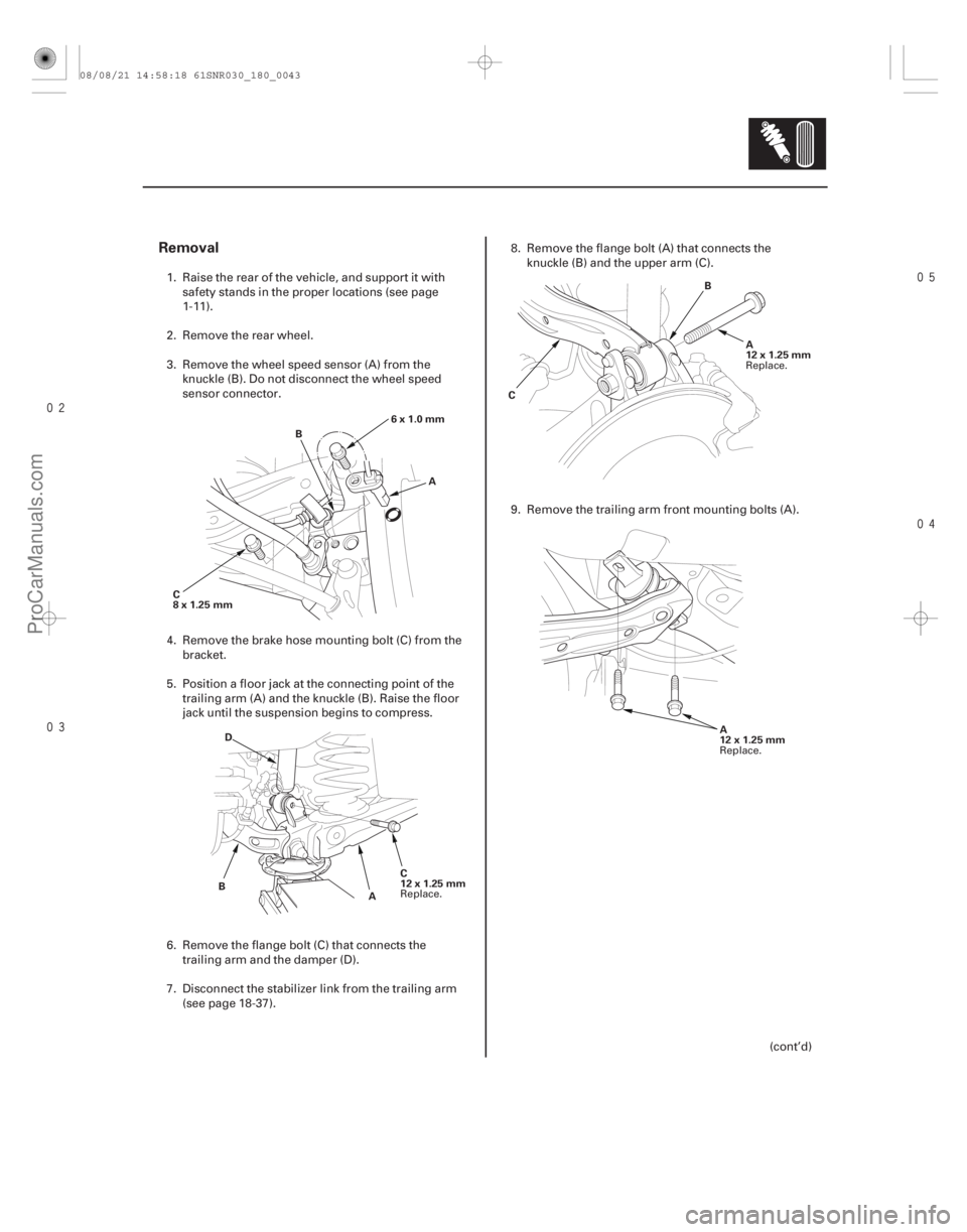
B B
C A
12x1.25mm
A
12x1.25mm
1. Raise the rear of the vehicle, and support it with safety stands in the proper locations (see page
1-11).
2. Remove the rear wheel.
3. Remove the wheel speed sensor (A) from the knuckle (B). Do not disconnect the wheel speed
sensor connector.
4. Remove the brake hose mounting bolt (C) from the bracket.
5. Position a floor jack at the connecting point of the trailing arm (A) and the knuckle (B). Raise the floor
jack until the suspension begins to compress.
6. Remove the flange bolt (C) that connects the trailing arm and the damper (D).
7. Disconnect the stab ilizer link from the trailing arm
(see page 18-37). 8. Remove the flange bolt (A) that connects the
knuckle (B) and the upper arm (C).
9. Remove the trailing arm front m ounting bolts (A).
(cont’d)
Replace. Replace.
Replace.
08/08/21 14:58:18 61SNR030_180_0043
ProCarManuals.com
DYNOMITE -2009-