Page 130 of 2893
�
�����
�(�#�'�����������
��������������������� �����)���
5-295-29
Transmission Mount Replacement
12x1.25mm
64 N·m
(6.5 kgf·m, 47 lbf·ft) A
22. Raise the vehicle on the lift.
23. M/T model: Tighten the front mount mounting bolt.
24. Install the splash shield (see step 40 on page 5-20).1. Loosen the upper torque rod mounting bolt (A).
2. Remove the air cleaner assembly (see page 11-345).
3. Remove the engine control module (ECM)/
powertrain control module (PCM) cover, then
remove the three bolts securing the ECM/PCM (see
step 10 on page 5-4).
4. Remove the under hood fuse/relay box from the ECM/PCM bracket, then remove the ECM/PCM
bracket(seestep13onpage5-4).
(cont’d)
08/08/21 14:21:04 61SNR030_050_0029
ProCarManuals.com
DYNOMITE -2009-
Page 133 of 2893
�
�����
����
�(�#�'�����������
��������������������� �����)����
5-325-32 Engine Assembly
Transmission Mount Replacement
(cont’d)
Lower Torque Rod Replacement
12x1.25mm
64 N·m
(6.5 kgf·m, 47 lbf·ft) A
A
22. Install the ECM/PCM bracket, then install the under- hood fuse/relay box to the ECM/PCM bracket (see
step 52 on page 5-22).
23. Install the ECM/PCM, then install the ECM/PCM cover (see step 56 on page 5-23)
24. Install the air cleaner assembly (see page 11-345).
25. Raise the vehicle on the lift.
26. M/T model: Tighten the front mount mounting bolt.
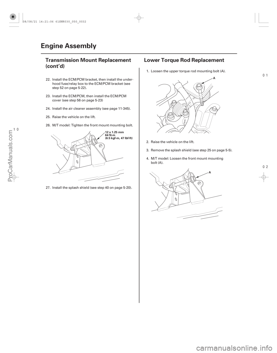
27. Install the splash shield (see step 40 on page 5-20). 1. Loosen the upper torque rod mounting bolt (A).
2. Raise the vehicle on the lift.
3. Remove the splash shield (see step 25 on page 5-5).
4. M/T model: Loosen the front mount mounting
bolt (A).
08/08/21 14:21:06 61SNR030_050_0032
ProCarManuals.com
DYNOMITE -2009-
Page 134 of 2893
�
�����
����
�(�#�'�����������
��������������������� �����)����
5-325-32 Engine Assembly
Transmission Mount Replacement
(cont’d)
Lower Torque Rod Replacement
12x1.25mm
64 N·m
(6.5 kgf·m, 47 lbf·ft) A
A
22. Install the ECM/PCM bracket, then install the under- hood fuse/relay box to the ECM/PCM bracket (see
step 52 on page 5-22).
23. Install the ECM/PCM, then install the ECM/PCM cover (see step 56 on page 5-23)
24. Install the air cleaner assembly (see page 11-345).
25. Raise the vehicle on the lift.
26. M/T model: Tighten the front mount mounting bolt.
27. Install the splash shield (see step 40 on page 5-20). 1. Loosen the upper torque rod mounting bolt (A).
2. Raise the vehicle on the lift.
3. Remove the splash shield (see step 25 on page 5-5).
4. M/T model: Loosen the front mount mounting
bolt (A).
08/08/21 14:21:06 61SNR030_050_0032
ProCarManuals.com
DYNOMITE -2009-
Page 256 of 2893
����
�(�#�'�������������������������������
�������)����
8-6Engine Lubrication
Low Oil Pressure Indicator Circuit Diagram
D2
Q9
H1
191
17
36
B7
CANL
CANH DRIVERBRN
12 V
5V GAUGE CONTROL MODULE (TACH)
IGNITION SWITCH
BATIG1
ECM/PCM
OPSW
A37
A36 RED
WHT CPU
No. 2 (50 A)
No. 10
(7.5 A)
BATTERY
UNDER-HOOD FUSE/RELAY BOX
No. 1 (100 A)
YEL/REDUNDER-DASH
FUSE/RELAY BOX
LOW OIL
PRESSURE
INDICATOR
OIL PRESSURE SWITCH
(Closed: Lost pressure)
IG1 HOT in ON (II)
and START (III)
1
WHT BLU
CANH
CANL
08/08/21 14:36:41 61SNR030_080_0006
ProCarManuals.com
DYNOMITE -2009-
Page 316 of 2893
����
�(�#�'�����������
���������
�����������������)����
10-23
Fan Controls
Component Location Index
FAN CONTROL RELAY
UNDER-HOOD FUSE/RELAY BOX
RADIATOR FAN RELAY
A/C CONDENSER FAN ASSEMBLY RADIATOR FAN ASSEMBLY ENGINE COOLANT TEMPERATURE
(ECT) SENSOR 2ENGINE COOLANT TEMPERATURE
(ECT) SENSOR 1
A/C CONDENSER FAN RELAY
Test, page 22-70
Test, page 22-70
Motor Test, page 10-5
Replacement, page 10-19 Motor Test, page 10-5
Replacement, page 10-19 Replacement, page 11-225Replacement, page 11-225
Test, page 22-70
08/08/21 14:40:31 61SNR030_100_0023
ProCarManuals.com
DYNOMITE -2009-
Page 318 of 2893
����
�(�#�'�����������
���������
�����������������)����
10-25
Circuit Diagram
ECT2
SG6
SG2
ECT1 FANH
FANL
SUBRLY IG2HOTinON(II)
PNK
5V No. 15 (7.5 A)
A21
PUR
ECM/PCM
2G301
BLK
2
1
No. 11 (15 A)
(10 A) No. 36
B23
RED/WHT GRN/BLK B33
BLU GRY
BRN
A33
BLK GRN A9 IGNITION SWITCH
IG2
BAT
RED
3
2 5
4 1
A4
A5 13
4
2
1 2 23 4
1 No. 2 (50 A)
BLK
UNDER-HOOD FUSE/RELAY BOX
BATTERY
G301No. 1 (100 A)
No. 6 (20 A)
A/C
CONDENSER
FAN RELAY
ENGINE COOLANT
TEMPERATURE
(ECT) SENSOR 1
A/C
CONDENSER
FAN MOTOR
FAN
CONTROL
RELAY
RADIATOR
FAN
MOTOR
ENGINE COOLANT
TEMPERATURE
(ECT) SENSOR 2 RADIATOR
FAN
RELAY
PGM-FI
SUB RELAY
H1
3 4
ORN
G12
D1
F16
F7
F2
F12
F14
F1
F11 No. 7 (20 A)
21
1 UNDER-DASH
FUSE/RELAY
BOX
BRN
WHT
43
12 C3
08/08/21 14:40:32 61SNR030_100_0025
ProCarManuals.com
DYNOMITE -2009-
Page 319 of 2893
����
�µ
�µ
�µ
�µ
�µ
�µ �µ
�µ
YES
NO
YES
NO
YES
NO
YES
NO
10-26Fan Controls
Radiator Fan High Speed Circuit Troubleshooting")
����
�����
�����
�(�#�'�����������
���������
�������
���������)����
�µ
�µ
�µ
�µ
�µ
�µ �µ
�µ
YES
NO
YES
NO
YES
NO
YES
NO
10-26Fan Controls
Radiator Fan High Speed Circuit Troubleshooting
RADIATOR FAN RELAY 4P SOCKET
FAN CONTROL RELAY 5P SOCKET
JUMPER WIRE
RADIATOR FAN RELAY 4P SOCKET JUMPER WIRE
1. Check the No. 7 (20 A) fuse in the under-hood fuse/relay box and the No. 36 (10 A) fuse in the under-
dash fuse/relay box.
Reinstall the fuse(s), then go to step 2.
Replace the fuse(s), and recheck. If the fuse
continues to blow, locate and repair the short in the
circuit between the under-hood fuse/relay box and
the radiator fan motor, or between the under-dash
fuse/relay box connector terminal G12, the under-
hood fuse/relay box and the engine control module
(ECM)/powertrain control module (PCM).
2. Remove the radiator fan relay and the fan control relay from the under-hood fuse/relay box, and test
them (see page 22-70).
Go to step 3.
Replace the radiator fan relay and/or fan
control relay.
3. Measure the voltage between the radiator fan relay 4P socket terminal No. 1 and body ground.
Go to step 4.
Replace the under-hood fuse/relay box. 4. Connect fan control relay 5P socket terminals No. 1
andNo.2withajumperwire.
5. Connect radiator fan relay 4P socket terminals No. 1 and No. 2 with a jumper wire.
Go to step 10.
Go to step 6.
Terminal side of female terminals Terminal side of female terminals
Terminal side of female terminals
Ar e t he f uses OK ? Ar e t he r el ay s OK ?
Is there battery voltage? Does t he r ad i at or f an r un at hi gh speed ?
08/08/21 14:40:32 61SNR030_100_0026
ProCarManuals.com
DYNOMITE -2009-
Page 321 of 2893

FAN CONTROL RELAY 5P SOCKET
RADIATOR FAN MOTOR 2P CONNECTOR RED RADIATOR FAN R")
����������
�µ
�µ �µ
�µ
YES
NO YES
NO
10-28Fan Controls
Radiator Fan High Speed Circuit Troubleshooting (cont’d)
FAN CONTROL RELAY 5P SOCKET
RADIATOR FAN MOTOR 2P CONNECTOR RED RADIATOR FAN RELAY 4P SOCKET
9. Check for continuity between fan control relay 5P
socket terminal No. 1 and radiator fan motor 2P
connector terminal No. 1.
Check for poor connections or loose
terminals at the under-hood fuse/relay box, the
radiator fan motor, and body ground (G 301), then
go to step 1.
Repair open in the wire between fan control
relay 5P socket terminal No. 1 and radiator fan
motor 2P connector terminal No. 1. 10. Turn the ignition switch to ON (II).
11. Measure the voltage between radiator fan relay 4P
socket terminal No. 3 and body ground.
Go to step 12.
Repair open in the wire between the under-
dash fuse/relay box and the under-hood fuse/relay
box.
12. Turn the ignition switch to LOCK (0).
13. Connect the Honda Diagnostic System (HDS) to the data link connector (DLC) (see step 2 on page 11-3).
14. Turn the ignition switch to ON (II).
15. Make sure the HDS communicates with the vehicle and the ECM/PCM. If it does not communicate,
troubleshoot the DLC circuit (see page 11-204).
16. Jump the SCS line with the HDS, then turn the ignition switch to LOCK (0).
NOTE: This step must be done to protect the ECM/
PCMfromdamage.
17. Disconnect ECM/PCM connector A (44P).
Terminal side of female termianls
Wire side of female terminals Terminal side of female terminals
Is there continuity?
Is there battery voltage?
08/08/21 14:40:33 61SNR030_100_0028
ProCarManuals.com
DYNOMITE -2009-