Page 1904 of 2893
�•�•�•
�•�•�•
�•�•�•
�•�•�•
�•�•�•
�•�•�•
�•�•�•
�•�•�•
�•�•�•
�•�•�•
�•�•�•
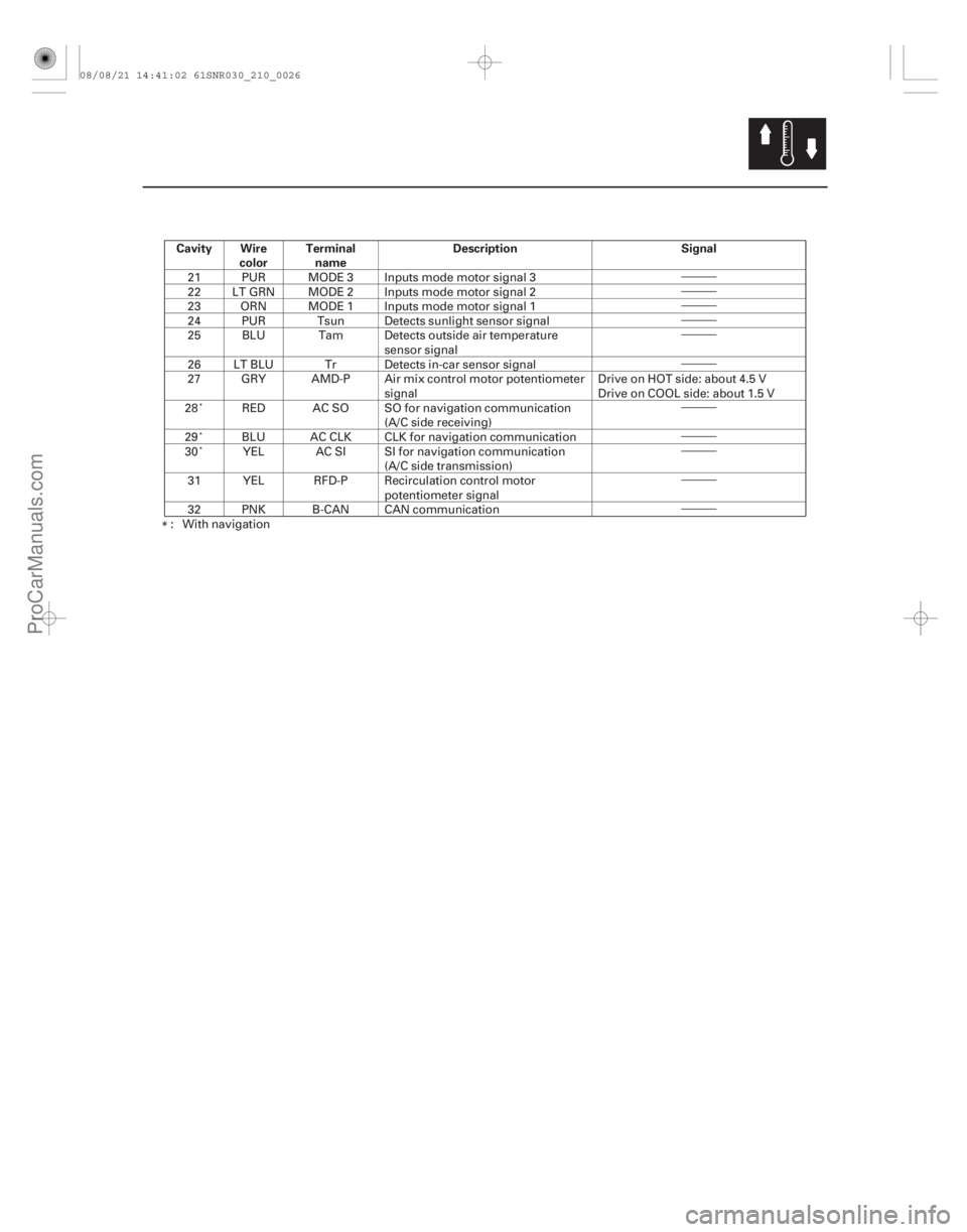
Cavity Wirecolor Terminal
name Description Signal
21-25
21 PUR MODE 3 Inputs mode motor signal 3
22 LT GRN MODE 2 Inputs mode motor signal 2
23 ORN MODE 1 Inputs mode motor signal 1
24 PUR Tsun Detects sunlight sensor signal
25 BLU Tam Detects outside air temperature
sensor signal
26 LT BLU Tr Detects in-car sensor signal
27 GRY AMD-P Air mix control motor potentiometer signal Drive on HOT side: about 4.5 V
Drive on COOL side: about 1.5 V
28 RED AC SO SO for navigation communication (A/C side receiving)
29 BLU AC CLK CLK for navigation communication
30 YEL AC SI SI for navigation communication (A/C side transmission)
31 YEL RFD-P Recirculation control motor potentiometer signal
32 PNK B-CAN CAN communication
: With navigation
08/08/21 14:41:02 61SNR030_210_0026
ProCarManuals.com
DYNOMITE -2009-
Page 1906 of 2893
����
21-27
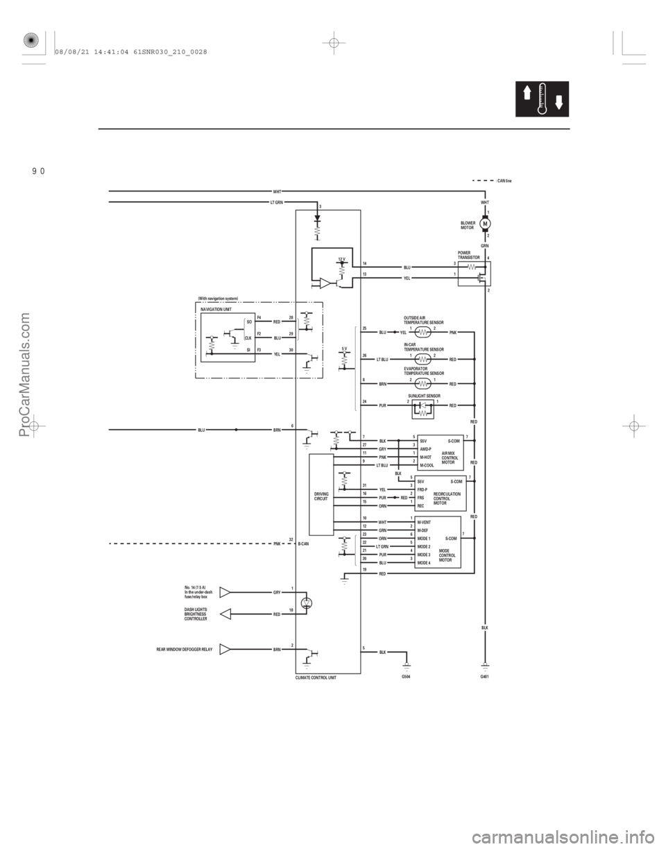
RED
(With navigation system)
30 29 28
F3 F2 F4
NAVIGATION UNIT
CLKSO
BLU
RED
YEL 12 V
PURBLU
LT GRN
BRN
BRN
BLU
REAR WINDOW DEFOGGER RELAY DASH LIGHTS
BRIGHTNESS
CONTROLLER
GRY
1
RED 18
2
32 6
PNK 5
3
19 20 21
22 23
12 10 15 16
31 9 11 27 7 24 8 26 25 13 14
G5041
1 2 2
2
YEL
RED REDPNK
LT BLU
RED RED
WHT BLU
LT GRN
PUR
ORN GRN RED
YEL
ORN GRY
PNK
LT BLU YEL
BLU
4
2
1
S-COM
REC
FRS FRD-P S5V
S-COM
M-DEF
M-VENT
MODE 4 MODE 2
MODE 3 MODE 1
2 2 1
BRN
PUR BLK
RED BLK
5V
1
3 5
4 6 1 2
3 5 BLK
CLIMATE CONTROL UNIT 1
2 1
RED
G401GRN
3
WHT
5
3
1
2
BLK
S5V
AMD-P
M-HOT
M-COOLS-COM WHT
7 7
7
DRIVING
CIRCUIT BLOWER
MOTOR
POWER
TRANSISTOR
OUTSIDE AIR
TEMPERATURE SENSOR
AIR MIX
CONTROL
MOTOR
RECIRCULATION
CONTROL
MOTOR
MODE
CONTROL
MOTOR
IN-CAR
TEMPERATURE SENSOR
EVAPORATOR
TEMPERATURE SENSOR
SUNLIGHT SENSOR
No. 14 (7.5 A)
In the under-dash
fuse/relay box SI
: CAN line
B-CAN
08/08/21 14:41:04 61SNR030_210_0028
ProCarManuals.com
DYNOMITE -2009-
Page 1933 of 2893
����
�µ
�µ
�µ
�µ
�µ
�µ �µ
�µ
YES
NO
YES
NO
YES
NO
YES
NO
21-54Climate Control
Navigation Communication Line Circuit Troubleshooting")
����
�����
�(�#�'�����#�
���
�����������
���������������)����
�µ
�µ
�µ
�µ
�µ
�µ �µ
�µ
YES
NO
YES
NO
YES
NO
YES
NO
21-54Climate Control
Navigation Communication Line Circuit Troubleshooting
NAVIGATION UNIT CONNECTOR F (5P)
CLIMATE CONTROL UNIT 32P CONNECTOR
REDBLU YEL
YEL
BLU
RED
CLIMATE CONTROL UNIT 32P CONNECTOR
NAVIGATION UNIT CONNECTOR D (12P) BLU
YEL
BLU
YEL
RED
RED
1. Operate the climate control system in severalmodes.
Go to step 2.
Do the self-diagnostic with the HDS (see page
21-10) or climate control unit (see page 21-11).
2. Do the Navi system link (see page 23-135).
’06-08models:Gotostep3.
’09 model: Go to step 7. Go to step 13.
3. Turn the ignition switch to LOCK (0).
4. Disconnect navigation unit connector F (5P).
5. Disconnect climate control unit 32P connector.
6. Check for continuity between the following terminals of climate control unit 32P connector and
navigation unit connector F (5P).
32P: 5P:
No. 28 No. 4
No. 29 No. 2
No. 30 No. 3
Go to step 11.
Repair open in the wire(s) between the
climate control unit and the navigation unit. 7. Turn the ignition switch to LOCK (0).
8. Disconnect navigation unit connector D (12P).
9. Disconnect climate control unit 32P connector.
10. Check for continuity between the following terminals of climate control unit 32P connector and
navigation unit connector D (12P).
32P: 12P:
No. 28 No. 6
No. 29 No. 12
No. 30 No. 5
Go to step 11.
Repair open in the wire(s) between the
climate control unit and the navigation unit.
Wire side of female terminals Wire side of female terminals
Wire side of female terminals
Wire side of female terminals
I s t he cl i mat e cont r ol sy st em OK ? Is the Air-Con icon red?
Is there continuity? Is there continuity?
08/08/21 14:42:24 61SNR030_210_0055
ProCarManuals.com
DYNOMITE -2009-
Page 1934 of 2893

����������
�µ
�µ �µ
�µ
YES
NO
YES
NO
21-55
CLIMATE CONTROL UNIT 32P CONNECTOR
REDYEL
BLU CLIMATE CONTROL UNIT 32P CONNECTOR
REDBLUYEL
JUMPER WIRE
11. Check for continuity between body ground and climate control unit 32P connector terminals No. 28,
29, and No. 30 individually.
Repair short to body ground in the wire(s)
between the climate control unit and the navigation
unit.
Go to step 12.
12. Reconnect climate control unit 32P connector.
13. ’06-08 models: Disconnect navigation unit connector F (5P).
’09 model: Disconnect navigation unit connector D
(12P). 14. Connect climate control unit 32P connector
terminals No. 28, 29, and No. 30 with a jumper wire.
15. Turn the ignition switch to ON (II).
16. Press the RECIRCULATION and OFF buttons. Troubleshoot the navigation system: ’06-08
models (see page 23-130), ’09 model (see page
23-346).
Substitute a known-good climate control unit,
and recheck. If the symptom goes away, replace
the original climate control unit.
Wire side of female terminals Wire side of female terminals
Is there continuity?
Does the RECIRCULAT ION indicator turn on?
08/08/21 14:42:25 61SNR030_210_0056
ProCarManuals.com
DYNOMITE -2009-
Page 1947 of 2893
���� ���
�(�#������������
�������������������
� �����)����
�µ
21-6721-67
In-car Temperature Sensor Test In-car Temperature Sensor Replacement
IN-CA")
���
�(�#�'�����������
�������������������
�������)���� ���
�(�#�'�����������
�������������������
� �����)����
�µ
21-6721-67
In-car Temperature Sensor Test In-car Temperature Sensor Replacement
IN-CAR TEMPERATURE SENSOR
10
14 0
32 10
5020
68 30
86
40 °C
104 °F
TEMPERATURE
RESISTANCE
(k )
12
11
10
98
7
6
5
4 3
2
1 A
B
1. Remove the in-car temperature sensor (see page21-67).
2. Test the in-car temperature sensor while holding it in front of the dashboard center vent.
Measure the resistance with the system set to Max Cool.
Measure the resistance with the system set to Max Hot.
3. Compare the resistance reading between terminals No. 1 and No. 2 of the in-car temperature sensor
with the specifications shown in the graph; the
resistance should be within the specifications.
4. If the resistance is not as specified, replace the in-car temperature sensor (see page 21-67). 1. Remove the center panel:
’06-08 models with navigation (see page 23-155)
’06-08 models without navigation (see page23-80)
’09 model with navigation (see page 23-355)
’09 model without navigation (see page 23-256)
2. Remove the self-tapping screw and the in-car temperature sensor (A) from the center panel (B).
3. Install the sensor in the reverse order of removal. Be sure to connect the air hose securely.
08/08/21 14:43:34 61SNR030_210_0068
ProCarManuals.com
DYNOMITE -2009-
Page 1955 of 2893
���� ���
����
�(�#����������������
���������������
� �����)����
21-7521-75
Climate Control Unit Removal/
Installation Dust and Pollen Filter Replace")
���
�(�#�'�����������
�����������
�����
�
� �����)���� ���
����
�(�#�'���������������
���������������
� �����)����
21-7521-75
Climate Control Unit Removal/
Installation Dust and Pollen Filter Replacement
B
A A
A
B
1. Remove the center panel: ’06-08 models with navigation (see page 23-155)
’06-08 models without navigation (see page23-80)
’09 model with navigation (see page 23-355)
’09 model without navigation (see page 23- 256)
2. Remove the dials (A), the self-tapping screws, and the climate control unit (B).
3. Install the control unit in the reverse order of removal. After installation, operate the various
functions to see whether works properly.
4. Run the self-diagnostic function to confirm that there are no problems in the system (see page
21-11). 1. Open the glove box. Remove the glove box stop on
each side, then let the glove box hang down
(see page 20-104).
2. Remove the dust and pollen filter assembly (A) from the evaporator.
3. Remove the filter (A) from the housing (B), and replace the filter.
4. Install the filter in the reverse order of removal. Make sure that there is no air leaking out of the
evaporator.
08/08/21 14:43:39 61SNR030_210_0076
ProCarManuals.com
DYNOMITE -2009-
Page 1999 of 2893
�����
22-9
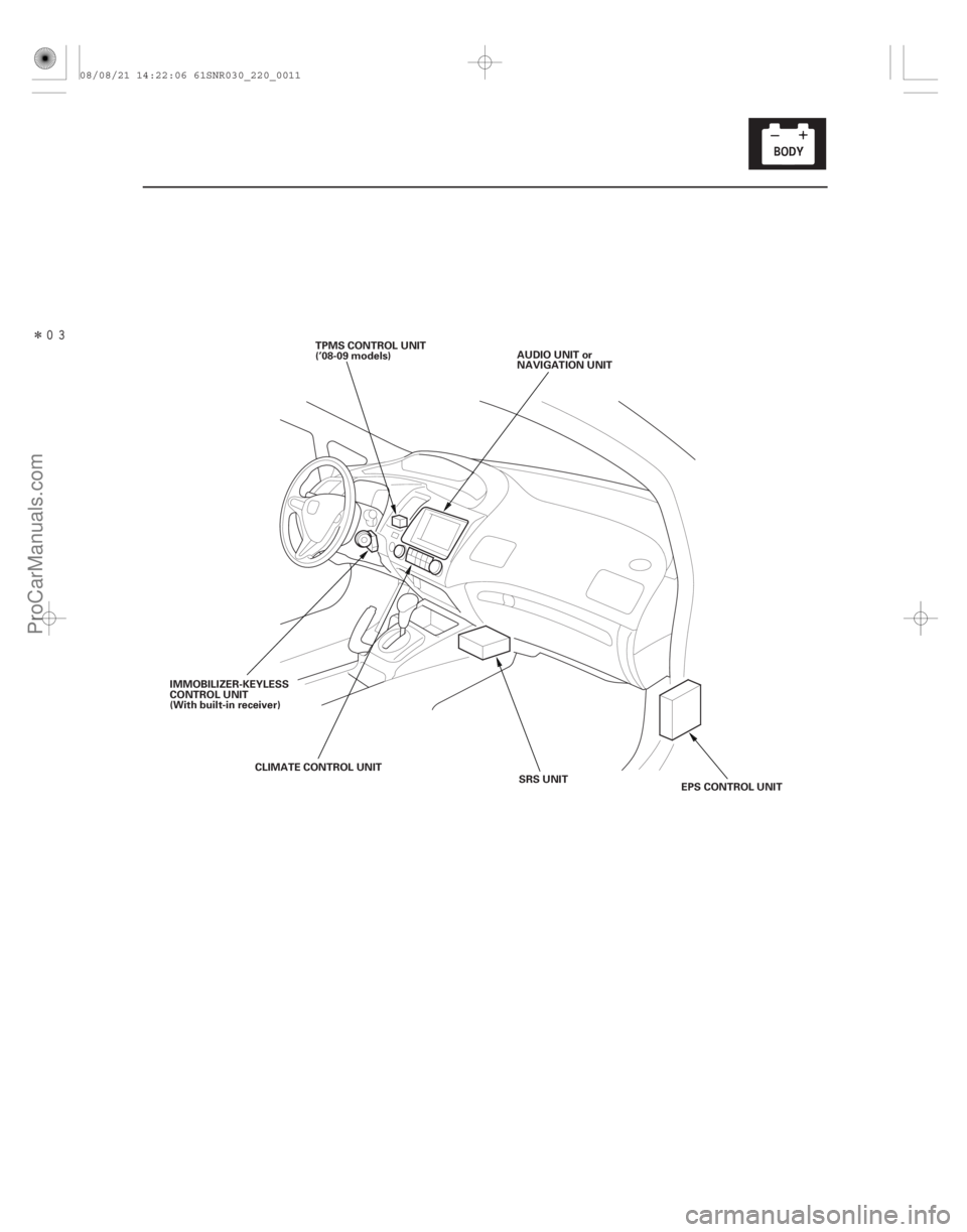
SRS UNIT
CLIMATE CONTROL UNIT
IMMOBILIZER-KEYLESS
CONTROL UNIT
(With built-in receiver)
EPS CONTROL UNIT
AUDIO UNIT or
NAVIGATION UNIT
TPMS CONTROL UNIT
(’08-09 models)
08/08/21 14:22:06 61SNR030_220_0011
ProCarManuals.com
DYNOMITE -2009-
Page 2000 of 2893
������(�#�'���������������������������������������)����
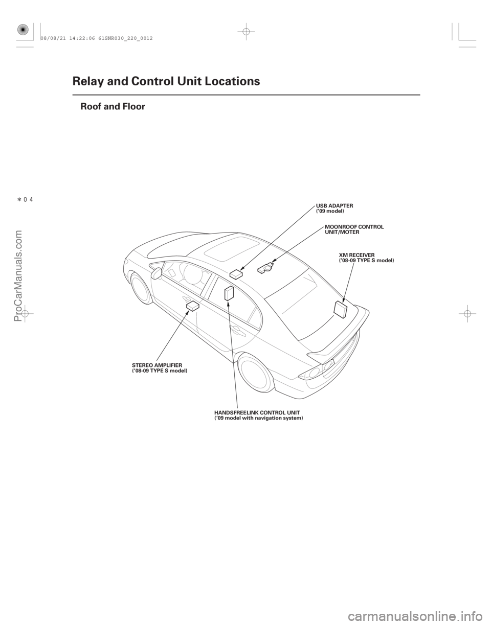
22-10Relay and Control Unit Locations
Roof and Floor
STEREO AMPLIFIER
(’08-09 TYPE S model)
MOONROOF CONTROL
UNIT/MOTER
USB ADAPTER
(’09 model)
XM RECEIVER
(’08-09 TYPE S model)
HANDSFREELINK CONTROL UNIT
(’09 model with navigation system)
08/08/21 14:22:06 61SNR030_220_0012
ProCarManuals.com
DYNOMITE -2009-