Page 2142 of 2893
���� ���
����
�(�#����������������
����������������� �����)���
22-19222-192 Turn Signal/Hazard Warning Lights
Hazard Warning Switch Test/")
���
����
�����(�#�'���������������
���������
�����
�������)���� ���
����
�(�#�'���������������
����������������� �����)���
22-19222-192 Turn Signal/Hazard Warning Lights
Hazard Warning Switch Test/
Replacement
Side Turn Signal Light Replacement
A
A
Terminal
Position 12
4
5
OFF ON A
A
B
1. Remove the center panel. With audio:– ’06-08 models (see page 23-80)
– ’09 model (see page 23-256)
With navigation: – ’06-08 models (see page 23-155)
– ’09 model (see page 23-355)
2. Remove the screws and the hazard warning switch (A).
3. Check for continuity between the terminals in each switch position according to the table.
4. If the continuity is not as specified, replace the bulb (A) or the hazard warning switch.
5. Install the hazard warning switch in the reverse order of removal. 1. Remove the mirror holder (see page 20-34).
2. Remove the four screws and the mirror visor (A).
3. Disconnect the 2P connector (A) from the side turn
signal light (B), then remove the side turn signal
light.
4. Install the side turn signal light in the reverse order of removal.
08/08/21 14:27:45 61SNR030_220_0194
ProCarManuals.com
DYNOMITE -2009-
Page 2146 of 2893
�
�� ����
����
�(�#��������������������������������
�������)�
�
With moonroof Without moonroof
Front Individual Map Light: 8 W x 2 Front")
����
����
�(�#�'�������������������������������
�������)�
�� ����
����
�(�#�'�������������������������������
�������)�
�
With moonroof Without moonroof
Front Individual Map Light: 8 W x 2 Front Individual Map Light: 8 W x 2
22-19622-196Interior Lights
Front Individual Map Light Test/Replacement
A
B
C
Position 13
Terminal
RIGHT LEFT ON
OFF ON
OFF Body
ground A
B
C
Position 1
Terminal
RIGHT LEFT ON
OFF ON
OFF Body
ground
1. Turn the map light switch OFF.
2. Carefully pry the lens (A) off with a small
screwdriver.
3. Remove the screws, then remove the map lights (B) and moonroof switch or navigation microphone (C).
4. Disconnect the 3P connector from the map lights and the 10P connector from the moonroof switch or
navigation microphone.
5. Check for continuity between the terminals in each switch position according to the table.
6. If the continuity is not as specified, check the bulb(s). If the bulb(s) are OK, replace the light
assembly.
7. Install the map light in the reverse order of removal. 1. Turn the map light switch OFF.
2. Carefully pry the lens (A) off with a small
screwdriver.
3. Remove the screws, then remove the map lights (B).
4. Disconnect the 3P connector (C) from the map lights.
5. Check for continuity between the terminals in each switch position according to the table.
6. If the continuity is not as specified, check the bulb(s). If the bulb(s) are OK, replace the light
assembly.
7. Install the map light in the reverse order of removal.
08/08/21 14:27:50 61SNR030_220_0198
ProCarManuals.com
DYNOMITE -2009-
Page 2195 of 2893
�����
�µ
�µ
22-245
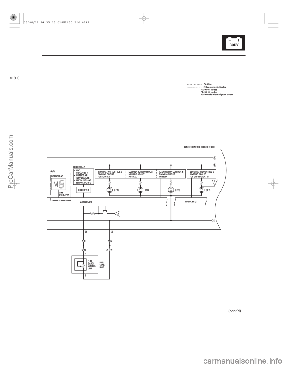
C
(LED)
LCD DISPLAY
LCD DRIVERMAIN CIRCUIT
33
ORN
ORN 32
LT GRN
3 1
PUR (LED)
(LED)
(LED)
C
LCD DISPLAY
B
A
GAUGE CONTROL MODULE (TACH)
ODO,
TRIP A/TRIP B
OUTSIDE AIR
TEMPERATURE
CHECK FUEL CAP
SERVICE OIL LIFE ILLUMINATION CONTROL &
DIMMING CIRCUIT
FOR POINTER
ILLUMINATION CONTROL &
DIMMING CIRCUIT
FOR DIALILLUMINATION CONTROL &
DIMMING CIRCUIT
FOR LCD
FUEL
GAUGE
SENDING
UNIT FUEL
TANK
UNIT ILLUMINATION CONTROL &
DIMMING CIRCUIT
FOR SHIFT INDICATOR
SHIFT
INDICATOR
(A/T)
MAIN CIRCUIT
A :CANline
: Other communication line
*1: ’06 07 models
*2: ’08 09 models
*3: ’09 model with navigation system
(cont’d)
08/08/21 14:35:13 61SNR030_220_0247
ProCarManuals.com
DYNOMITE -2009-
Page 2196 of 2893
 (cont’d)
G504
G503
SHIFT INDICATOR
AUDIO UNIT
NAVIGATION UNIT
HAZARD WARNING SWITCH LIGHT
MOONROOF SWITCH LIGHT
STEERING SWITCHES L")
����
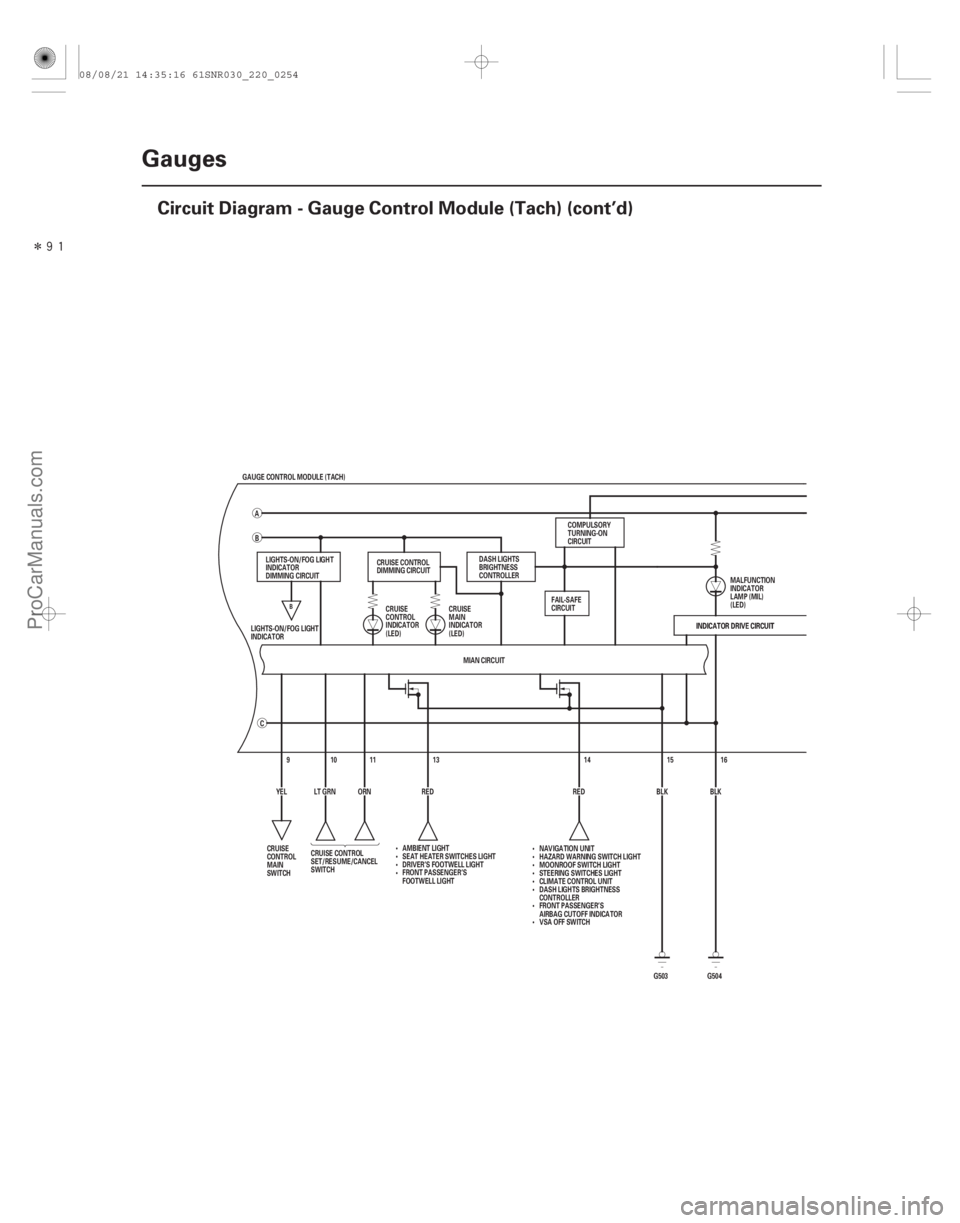
22-246Gauges
Circuit Diagram - Gauge Control Module (Tach) (cont’d)
G504
G503
SHIFT INDICATOR
AUDIO UNIT
NAVIGATION UNIT
HAZARD WARNING SWITCH LIGHT
MOONROOF SWITCH LIGHT
STEERING SWITCHES LIGHT
RED
GAUGE CONTROL MODULE (TACH)
MIAN CIRCUIT INDICATOR DRIVE CIRCUIT
16
15
14
13
91011
C
B
A
INDICATOR DRIVE CIRCUIT
BLK
BLK
RED
YEL LT GRN ORN
LIGHTS-ON/FOG LIGHT
INDICATOR
DIMMING CIRCUIT
CRUISE CONTROL
SET/RESUME/CANCEL
SWITCH CRUISE
CONTROL
INDICATOR
(LED)
DASH LIGHTS
BRIGHTNESS
CONTROLLER
A/T GEAR POSITION
INDICATOR COMPULSORY
TURNING-ON
CIRCUIT
CRUISE
DIMMING
CIRCUIT
LIGHTS-ON/FOG LIGHT
INDICATOR
CRUISE
CONTROL
MAIN
SWITCH FAIL-SAFE
CIRCUIT
COMPULSORY
TURNING-OFF
CIRCUIT
MALFUNCTION
INDICATOR
LAMP (MIL)
(LED)
A/T GEAR POSITION INDICATOR
PANEL LIGHT
AMBIENT LIGHT
SEAT HEATER SWITCHES LIGHT
CLIMATE CONTROL UNIT
DASH LIGHTS BRIGHTNESS
CONTROLLER
FRONT PASSENGER’S
AIRBAG CUTOFF INDICATOR
VSA OFF SWITCH CRUISE
MAIN
INDICATOR
(LED)
C
B
08/08/21 14:35:13 61SNR030_220_0248
ProCarManuals.com
DYNOMITE -2009-
Page 2202 of 2893
����
22-252Gauges
Circuit Diagram - Gauge Control Module (Tach) (cont’d)
RED
GAUGE CONTROL MODULE (TACH)
MIAN CIRCUIT INDICATOR DRIVE CIRCUIT
16
G504
15
14
13
91011
C
B
A
G503INDICATOR DRIVE CIRCUIT
BLK
BLK
RED
YEL LT GRN ORN
LIGHTS-ON/FOG LIGHT
INDICATOR
DIMMING CIRCUIT
CRUISE CONTROL
SET/RESUME/CANCEL
SWITCH CRUISE
CONTROL
INDICATOR
(LED)
DASH LIGHTS
BRIGHTNESS
CONTROLLER
COMPULSORY
TURNING-ON
CIRCUIT
CRUISE CONTROL
DIMMING CIRCUIT
LIGHTS-ON/FOG LIGHT
INDICATOR
CRUISE
CONTROL
MAIN
SWITCH FAIL-SAFE
CIRCUIT
MALFUNCTION
INDICATOR
LAMP (MIL)
(LED)
CRUISE
MAIN
INDICATOR
(LED)
AMBIENT LIGHT
SEAT HEATER SWITCHES LIGHT
DRIVER’S FOOTWELL LIGHT
FRONT PASSENGER’S
FOOTWELL LIGHT NAVIGATION UNIT
HAZARD WARNING SWITCH LIGHT
MOONROOF SWITCH LIGHT
STEERING SWITCHES LIGHT
CLIMATE CONTROL UNIT
DASH LIGHTS BRIGHTNESS
CONTROLLER
FRONT PASSENGER’S
AIRBAG CUTOFF INDICATOR
VSA OFF SWITCH
B
08/08/21 14:35:16 61SNR030_220_0254
ProCarManuals.com
DYNOMITE -2009-
Page 2206 of 2893
����
�µ
�´
�µ
22-256 Gauges
Circuit Diagram - Dash Lights Brightness Controller
RED
GRY
BRN45
YEL 6
BLU 7
PUR
BLK
2176
4
G501 13
RED
14
16
BLK B")
����
�(�#�'���������������������
�����������������)����
�µ
�´
�µ
22-256 Gauges
Circuit Diagram - Dash Lights Brightness Controller
RED
GRY
BRN45
YEL 6
BLU 7
PUR
BLK
2176
4
G501 13
RED
14
16
BLK BLK
G503
13
RED
16
BLK BLK
G504 15
MAIN CIRCUIT
WHT BRN
No. 2 (IG) (50 A)
GAUGE CONTROL MODULE (TACH) 18 17
ORN
IG1
BAT
BLU
WHT
No. 23 (10 A)
BATTERY
IGNITION SWITCH
No. 1 (BAT) (100 A)
(7.5 A) No. 10
UNDER-DASH
FUSE/RELAY
BOX IG1 HOT in ON (II)
and START (III)
DASH LIGHTS BRIGHTNESS CONTROLLER and
ODOMETER SELECT/RESET SWITCH
No. 14 (7.5 A) FUSE
(UNDER-DASH
FUSE/RELAY BOX)
GAUGE CONTROL
MODULE (TACH) km/h
mph
SEL/
RESET
ILLUMI
()
ILLUMI
()
H1
D4 G2D2
UNDER-HOOD FUSE/RELAY BOX
5
3LIGHTS
(LED) Q1 Q9
MICU A/T GEAR POSITION INDICATOR
PANEL LIGHT
AMBIENT LIGHT
SEAT HEATER SWITCHES LIGHT
DRIVER’S FOOTWELL LIGHT*1
FRONT PASSENGER’S
FOOTWELL LIGHT*1
CLIMATE CONTROL UNIT*2
DASH LIGHTS BRIGHTNESS
CONTROLLER*2
FRONT PASSENGER’S
AIRBAG CUTOFF INDICATOR*2
VSA OFF SWITCH*2
AUDIO UNIT
NAVIGATION UNIT
HAZARD WARNING SWITCH LIGHT
MOONROOF SWITCH LIGHT
STEERING SWITCHES LIGHT
CLIMATE CONTROL UNIT*1
DASH LIGHTS BRIGHTNESS
CONTROLLER*1
FRONT PASSENGER’S
AIRBAG CUTOFF INDICATOR*1
VSA OFF SWITCH*1
*1: TYPE S model
*2: Except TYPE S model
08/08/21 14:35:17 61SNR030_220_0258
ProCarManuals.com
DYNOMITE -2009-
Page 2226 of 2893
���
Release Locked odometer mileage to the
original gauge control module.
22-276 Gauges
Rewriting the ODO Data and Transferring the Maintenance")
�µ�µ�µ
�(�#�'���������������
�����������������������)���
Release Locked odometer mileage to the
original gauge control module.
22-276 Gauges
Rewriting the ODO Data and Transferring the Maintenance Minder Data to a
New Gauge Control Module
NOTE:
Obtain a new gauge control module before starting the rewriting process.
Rewriting is not possible on a gauge control module that will not communicate with the HDS.
Make sure that the HDS shows the correct VIN for the car you are working on.
One you have started this procedure, you must complete it before removing the HDS from the DLC.
Connect a battery jump box (not a Battery charger) to insure that correct battery voltage will be maintained.
1. Before replacing the gauge control module, connect the HDS.
2. Select GAUGES from the BODY ELECTRICAL menu display.
3. Select ‘‘Gauge Control M odule Replacement (ODO
rewrite)’’ from the ADJUSTMENT menu, and follow
the instructions on the display to retrieve the ODO
data and the Maintenance Minder information.
4. Replace the gauge control module.
5. Follow the instructions on the display to write the new ODO data and Maintenance Minder data to a
new gauge control module. If the data transfer fails,
refer to the instructions below to release the locked
ODO data. If after you attempt to transfer mileage the odometer
has dashes ( ), garbled, or incorrect value
displayed, do the following start over. The original
gauge control module is going to be unlocked and
restored to its original state.
1. Confirm that you have the latest HDS version of software.
2. Make sure that the HDS shows the correct VIN for the car you are working on.
3. With the ignition switch to LOCK (0), reconnect the original gauge assembly.
4. Completely re-boot the HDS.
5. Clear any stored DTCs.
6. Navigation to Body. Electric/Gauges/Adjustment/Instrument Panel
Replacement.
7. Select ‘‘3. Releasing Locked ODO Data’’.
8. Follow the prompts and the Odometer mileage will be restored.
9. Start over and make sure the screen prompts are followed.
08/08/21 14:35:59 61SNR030_220_0278
ProCarManuals.com
DYNOMITE -2009-
Page 2232 of 2893
����
�µ�µ
�µ
22-282 Reminder Systems
Circuit Diagram
MICU
ORN
(10 A) No. 23
BLK1 2
SRS UNIT
G602
B11
A12
A11 YEL
WHT REDRED")
����
�(�#�'�������������������
�
�����������������)����
�µ�µ
�µ
22-282 Reminder Systems
Circuit Diagram
MICU
ORN
(10 A) No. 23
BLK1 2
SRS UNIT
G602
B11
A12
A11 YEL
WHT REDRED
WHT
ORN28
LT GRN BLK16
G504
INDICATOR DRIVE CIRCUIT
MICU
ECM/PCM MAIN CIRCUIT
21
PNK
124
CAN L
CAN H
CHIME
WHT
BRN
RED 19
1
WHT No. 2 (IG) (50 A)
GAUGE CONTROL MODULE (TACH) 18
17
IG1
BAT
BLU
WHT
UNDER-HOOD FUSE/RELAY BOX
BATTERY IGNITION SWITCH
No. 1 (BAT) (100 A)
(7.5 A) No. 10UNDER-DASH
FUSE/RELAY
BOX
DRIVE
CIRCUIT
PARKING
BRAKE
REMINDER
SEAT
BELT
REMINDER
KEY-IN
REMINDER
F-CAN
TRANSCEIVER B-CAN
TRANSCEIVERLIGHTS-ON
INDICATOR
(LED)
IG1 HOT in ON (II)
and START (III)
ABS MODULATOR-
CONTROL UNIT*1 LIGHTS-ON INDICATOR
DIMMING CIRCUIT
PARKING
BRAKE
SWITCH
(Closed:
Lever pulled)
DRIVER’S
SEAT BELT
BUCKLE
SWITCH
(Closed:
unbuckled) SEAT BELT
REMINDER
INDICATOR
(LED)
BRAKE
SYSTEM
INDICATOR
(LED)COMPULSORY
TURNING-ON
CIRCUIT
LIGHTS-ON
REMINDER
CLIMATE
CONTROL
UNIT
IMMOBILIZER-
KEYLESS
CONTROL UNIT
HANDSFREELINK
CONTROL UNIT*4
H1
D4 D2
Q1 Q9
G2 :CANline
1
VSA MODULATOR-
CONTROL UNIT*2
YAW RATE-LATERAL
ACCELERATION SENSOR*2
DATA LINK CONNECTOR
EPS CONTROL UNIT
TPMS CONTROL UNIT*3 10 V
STABILIZING
CIRCUIT
*1: ’06 07 Touring and Premium models
*2: ’07 TYPE S and ’08 09 models
*3: ’08 09 models
*4: ’09 model with navigation system
MICU
A
B
08/08/21 14:36:02 61SNR030_220_0284
ProCarManuals.com
DYNOMITE -2009-