Page 2291 of 2893
����
�����
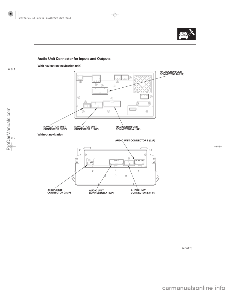
Audio Unit Connector for Inputs and Outputs
With navigation (navigation unit)
Without navigation
23-11
NAVIGATION UNIT
CONNECTOR B (22P)
NAVIGATION UNIT
CONNECTOR A (17P)
NAVIGATION UNIT
CONNECTOR E (14P)
NAVIGATION UNIT
CONNECTOR G (3P)
AUDIO UNIT CONNECTOR B (22P)
AUDIO UNIT
CONNECTOR E (14P)
AUDIO UNIT
CONNECTOR A (17P)
AUDIO UNIT
CONNECTOR G (3P)
(cont’d)
08/08/21 14:03:45 61SNR030_230_0014
ProCarManuals.com
DYNOMITE -2009-
Page 2292 of 2893

Except Type S model
Cavity Wire Color Connect toType S model
C")
�µ�µ
�µ
�µ
�µ �µ
�´ �´
�´
�´
�´ �´
�´ �µ
�µ
�µ�µ
�´
�´
�´�´
�´
�����
NAVIGATION UNIT/AUDIO UNIT CONNECTOR A (17P)
Except Type S model
Cavity Wire Color Connect toType S model
Cavity Wire Color Connect to
23-12Audio System
System Description (cont’d)
A1 RED Dash lights brightness
controller
A2 BRN Left rear speaker ( )
A3 PNK Driver’s door speaker ( ), Left tweeter ( )
A4 GRN Multiplex integrated control unit (MICU) (SCTY RADIO)
A6 LT BLU Multiplex integrated control unit(MICU)(K-LINE)
A7 BRN Front passenger’s door speaker ( ), Right tweeter
()
A8 ORN Right rear speaker ( )
A9 BLK Ground (G 505)
A10 GRY Lights-on signal
A11 YEL Left rear speaker ( )
A12 LT GRN Driver’s door speaker ( ), Left tweeter ( )
A13 BLU ECM/PCM (VSP)
A14 PUR Multiplex integrated control unit(MICU)(ACCRADIO)
A15 GRY Front passenger’s door speaker ( ), Right tweeter
()
A16 BLU Right rear speaker ( )
A17 WHT Multiplex integrated control unit (MICU) ( B BACK UP) A1 RED Dash lights brightness
controller
A2 WHT Stereo amplifier (RL SIG )
A3 ORN Stereo amplifier (FL SIG )
A4 GRN Multiplex integrated control unit (MICU) (SCTY RADIO)
A6 LT BLU Multiplex integrated control unit(MICU)(K-LINE)
A7 PNK Stereo amplifier (FR SIG )
A8 PUR Stereo amplifier (RR SIG )
A9 BLK Ground (G505)
A10 GRY Lights-on signal
A11 BLK Stereo amplifier (RL SIG )
A12 BLU Stereo amplifier (FL SIG )
A13 BLU ECM/PCM (VSP)
A14 PUR Multiplex integrated control unit(MICU)(ACCRADIO)
A15 BLU Stereo amplifier (FR SIG )
A16 LT GRN Stereo amplifier (RR SIG )
A17 WHT Multiplex integrated control unit (MICU) ( B BACK UP)
Wire side of female terminals
08/08/21 14:03:46 61SNR030_230_0015
ProCarManuals.com
DYNOMITE -2009-
Page 2293 of 2893
 (wit
hout
navigation)
Cavity Wire Color Connect to AUDIO UNIT CONNECTOR B (20P) (with navigation)
Cavity Wire Color Connect to
23-13
B1 BRN Auxiliary j")
�������
��
NAVIGATION UNIT CONNECTOR B (22P) (wit
hout
navigation)
Cavity Wire Color Connect to AUDIO UNIT CONNECTOR B (20P) (with navigation)
Cavity Wire Color Connect to
23-13
B1 BRN Auxiliary jack assembly (AUX SGND)
B2 GRY Shield for terminals No. 1, No. 3, No. 11, No. 12, and
No. 13 (AUX SH GND)
B3 BLU Auxiliary jack assembly (AUX GND)
B6 BRN Radio remote switch (AUDIO REMOTE GND)
B7 PNK Radio remote switch (AUDIO REMOTE SW)
B11 YEL Auxiliary jack assembly (AUX L)
B12 GRN Auxiliary jack assembly (AUX R)
B13 WHT Auxiliary jack assembly (AUX DET)
B20 LT BLU Stereo amplifier (AMP ON)
1: The shielded wires have a heat-shrunk tube insulating the outside of the wire. The color of the
insulating tube, typically black or dark gray, may
not match the color of the wire listed on the
schematic.
2: Type S model B3 BRN Auxiliary jack assembly
(AUX SGND)
B4 GRY Shield for terminals No. 3, No. 5, No. 13, No. 14, and
No. 15 (AUX SH GND)
B5 BLU Auxiliary jack assembly (AUX GND)
B6 BRN Radio remote switch (AUDIO REMOTE GND)
B7 PNK Radio remote switch (AUDIO REMOTE SW)
B13 YEL Auxiliary jack assembly (AUX L)
B14 GRN Auxiliary jack assembly (AUX R)
B15 WHT Auxiliary jack assembly (AUX DET)
: The shielded wires have a heat-shrunk tube insulating the outside of the wire. The color of the
insulating tube, typically black or dark gray, may
not match the color of the wire listed on the
schematic.
(cont’d)
1
2
Wire side of female terminals Wire side of female terminals
08/08/21 14:03:46 61SNR030_230_0016
ProCarManuals.com
DYNOMITE -2009-
Page 2294 of 2893
 (with
navigation)
Cavity Wire Color Connect to NAVIGATION UNIT/AUDIO UNIT CONNE")
�´
�´
�´
�´
�µ �µ
�µ
�•�•�•
�•�•�•
�•�•�• �´
�����
�����
NAVIGATION UNIT CONNECTOR E (14P) (with
navigation)
Cavity Wire Color Connect to NAVIGATION UNIT/AUDIO UNIT CONNECTOR G (3P)
Cavity Wire Color Connect to
23-14Audio System
System Description (cont’d)
E2 LT BLU XM receiver
(SAT SYS ACC)
E3 BRN Shield for terminals No. 9 and No. 10
(BUS SH GND)
E4 GRY Shield for terminals No. 5, No. 6, No. 13, and No. 14
(SAT SH GND)
E5 WHT XM receiver (SAT R )
E6 RED XM receiver (SAT L )
E7 BLU XM receiver ( B)
E9 BLU XM receiver (SAT BUS (GA-NET))
E10 PNK XM receiver (SAT BUS (GA-NET))
E11 BLK XM receiver (GND)
E13 BLK XM receiver (SAT R )
E14 GRN XM receiver (SAT L )
: The shielded wires have a heat-shrunk tube insulating the outside of the wire. The color of the
insulating tube, typically black or dark gray, may
not match the color of the wire listed on the
schematic. G1 AM/FM antenna amplifier (RF
IN)
G2 Shield for terminal No.1 (RF SH)
G3 AM/FM antenna amplifier (SWD B)
Wire side of female terminals Terminal side of female terminals
08/08/21 14:03:46 61SNR030_230_0017
ProCarManuals.com
DYNOMITE -2009-
Page 2296 of 2893

Cavity Wire Color Connect to STEREO AMPLIFIER CONNECTOR B (")
�´
�´ �´
�´
�´ �´
�´
�´ �µ
�µ �µ
�µ
�µ �µ
�µ �´
�´
�´�´
�µ
�µ
�µ�µ
��
�� �����
STEREO AMPLIFIER CONNECTOR A (20P)
Cavity Wire Color Connect to STEREO AMPLIFIER CONNECTOR B (14P)
Cavity Wire Color Connect to
23-16Audio System
System Description (cont’d)
A1 PNK Right tweeter ( )
A2 GRY Front passenger’s door
speaker ( )
A3 LT GRN Driver’s door speaker ( )
A4 RED Left tweeter ( )
A5 GRN Subwoofer ( )
A7 BLU Right rear speaker ( )
A8 GRY Left rear speaker ( )
A9 PUR Multiplex integrated control unit(MICU)(ACCRADIO)
A10 LT GRN B (Main stereo power supply)
A11 BLU Right tweeter ( )
A12 BRN Front passenger’s door speaker ( )
A13 PNK Driver’s door speaker ( )
A14 GRN Left tweeter ( )
A15 RED Subwoofer ( )
A17 ORN Right rear speaker ( )
A18 BRN Left rear speaker ( )
A20 BLK Ground (G 505) B1 BLU Navigation unit (FL SIG )
B2 BRN Shield for terminals No. 1 and
No. 8 (FL SH GND)
B3 BLK Navigation unit (RL SIG )
B4 BLU Navigation unit (FR SIG )
B5 GRY Shield for terminals No. 4 and No. 11 (FR SH GND)
B6 LT GRN Navigation unit (RR SIG )
B7 LT BLU Navigation unit (AMP ON)
B8 RED Navigation unit (FL SIG )
B9 GRN Shield for terminals No. 3 and No. 10 (RL SH GND)
B10 WHT Navigation unit (RL SIG )
B11 PNK Navigation unit (FR SIG )
B12 YEL Shield for terminals No. 6 and No. 13 (RR SH GND)
B13 PUR Navigation unit (RR SIG )
: The shielded wires have a heat-shrunk tube insulating the outside of the wire. The color of
the insulating tube, typically black or dark gray,
may not match the color of the wire listed on the
schematic.
Wire side of female terminals Wire side of female terminals
08/08/21 14:03:47 61SNR030_230_0019
ProCarManuals.com
DYNOMITE -2009-
Page 2297 of 2893
�����
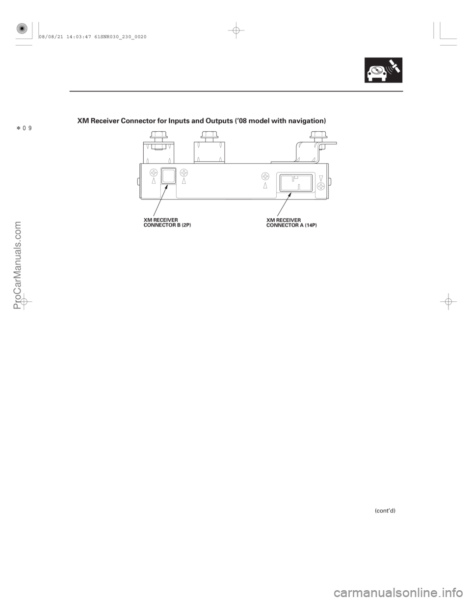
XM Receiver Connector for Inputs and Outputs (’08 model with navigation)
23-17
XM RECEIVER
CONNECTOR B (2P)XM RECEIVER
CONNECTOR A (14P)
(cont’d)
08/08/21 14:03:47 61SNR030_230_0020
ProCarManuals.com
DYNOMITE -2009-
Page 2298 of 2893
�´�´
�´
�´
�µ �µ
�µ�•�•�•
�•�•�•
��
��
��
�
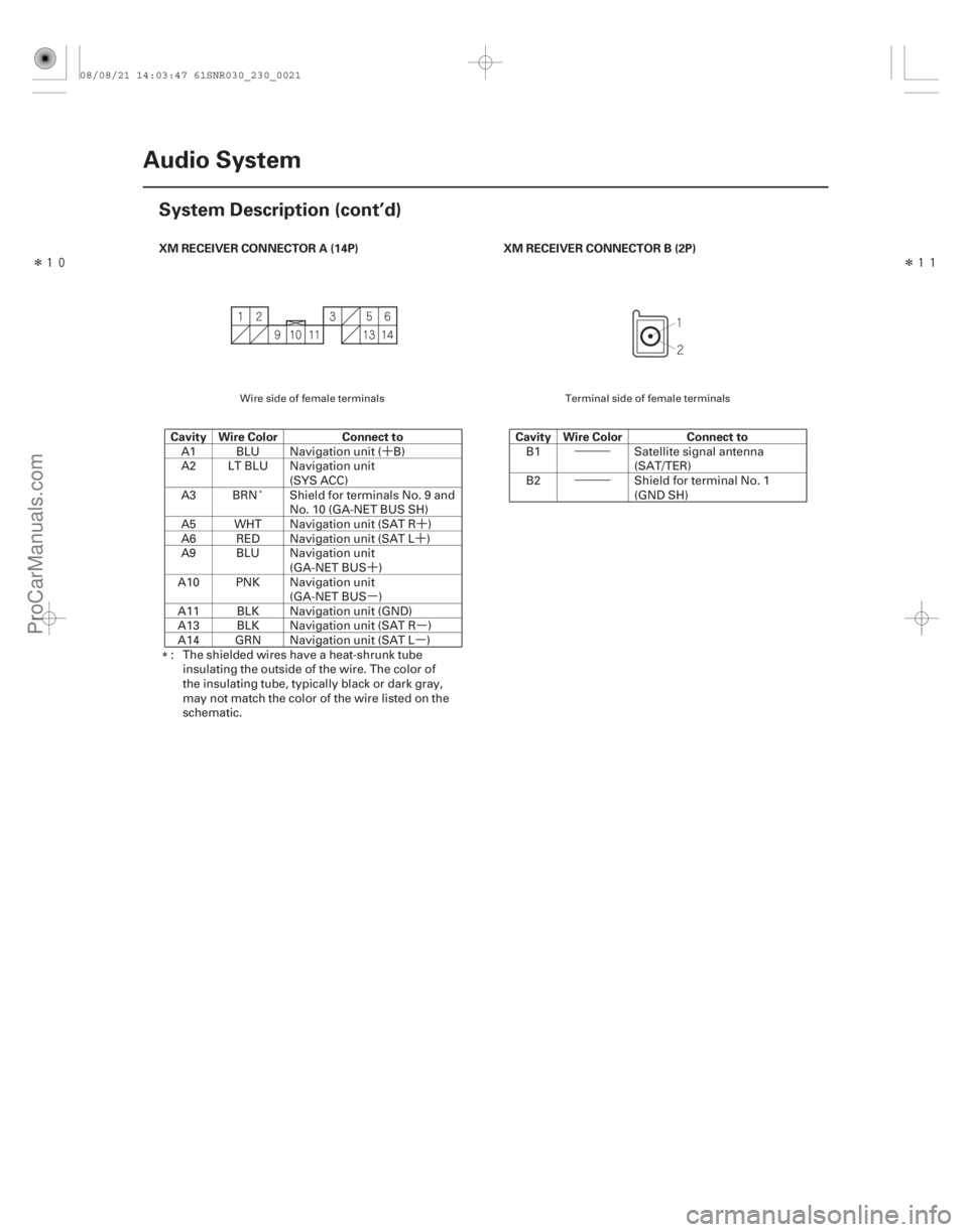
XM RECEIVER CONNECTOR A (14P)
Cavity Wire Color Connect to XM RECEIVER CONNECTOR B (2P)
Cavity Wire Color Connect to
23-18Audio System
System Description (cont’d)
A1 BLU Navigation unit ( B)
A2 LT BLU Navigation unit
(SYS ACC)
A3 BRN Shield for terminals No. 9 and No. 10 (GA-NET BUS SH)
A5 WHT Navigation unit (SAT R )
A6 RED Navigation unit (SAT L )
A9 BLU Navigation unit (GA-NET BUS )
A10 PNK Navigation unit (GA-NET BUS )
A11 BLK Navigation unit (GND)
A13 BLK Navigation unit (SAT R )
A14 GRN Navigation unit (SAT L )
: The shielded wires have a heat-shrunk tube insulating the outside of the wire. The color of
the insulating tube, typically black or dark gray,
may not match the color of the wire listed on the
schematic. B1 Satellite signal antenna
(SAT/TER)
B2 Shield for terminal No. 1 (GND SH)
Wire side of female terminals Terminal side of female terminals
08/08/21 14:03:47 61SNR030_230_0021
ProCarManuals.com
DYNOMITE -2009-
Page 2299 of 2893
��
����
��
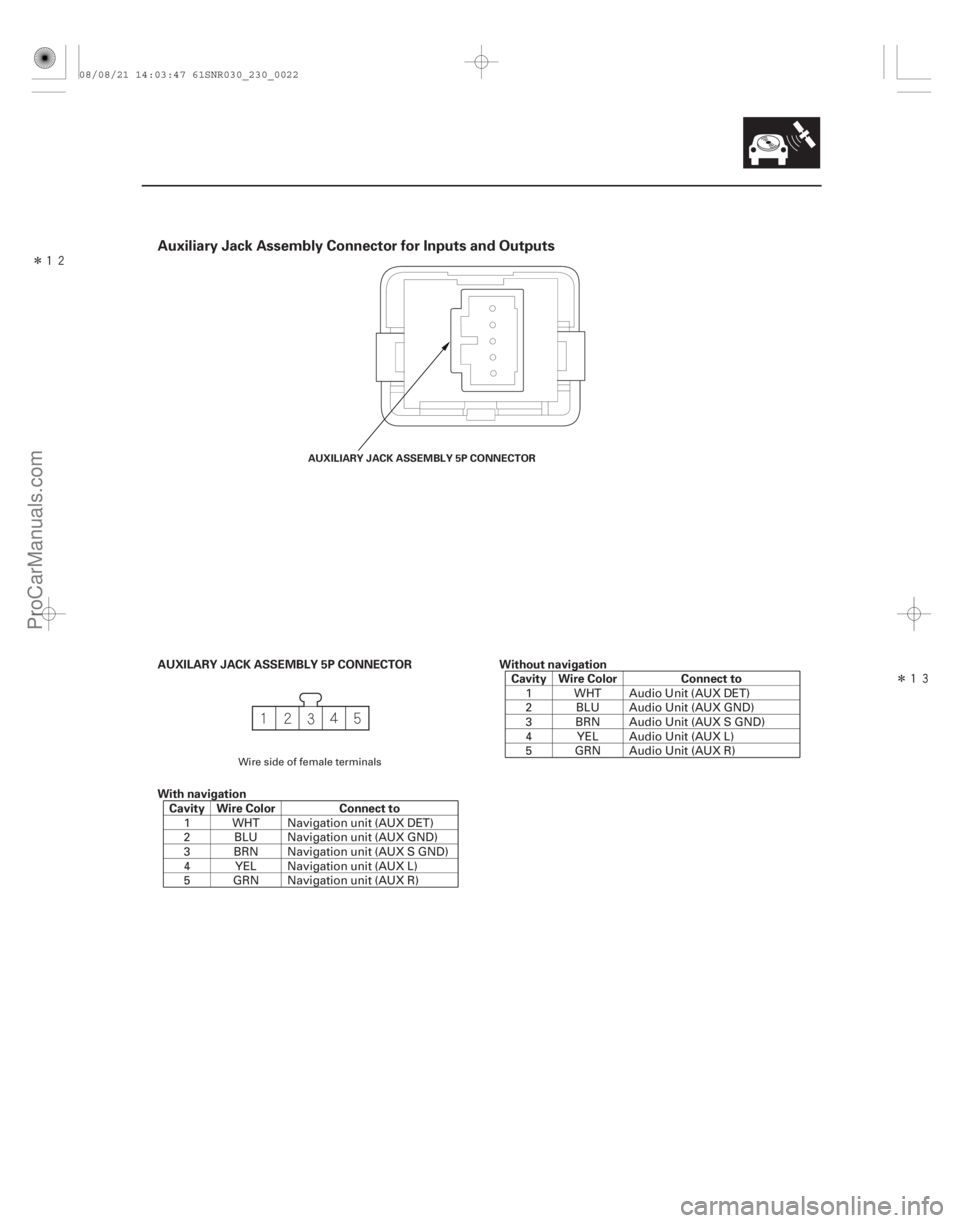
Auxiliary Jack Assembly Connector for Inputs and Outputs
AUXILARY JACK ASSEMBLY 5P CONNECTOR
With navigationCavity Wire Color Connect to Without navigation
Cavity Wire Color Connect to
23-19
AUXILIARY JACK ASSEMBLY 5P CONNECTOR
1 WHT Navigation unit (AUX DET)
2 BLU Navigation unit (AUX GND)
3 BRN Navigation unit (AUX S GND)
4 YEL Navigation unit (AUX L)
5 GRN Navigation unit (AUX R) 1 WHT Audio Unit (AUX DET)
2 BLU Audio Unit (AUX GND)
3 BRN Audio Unit (AUX S GND)
4 YEL Audio Unit (AUX L)
5 GRN Audio Unit (AUX R)
Wire side of female terminals
08/08/21 14:03:47 61SNR030_230_0022
ProCarManuals.com
DYNOMITE -2009-