Page 14 of 5135
01±40
± INTRODUCTIONTERMS
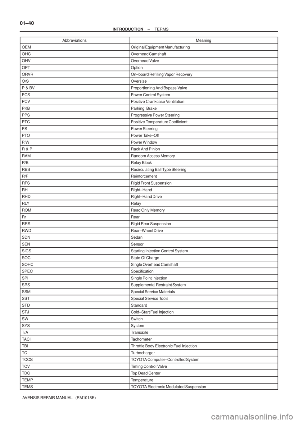
AVENSIS REPAIR MANUAL (RM1018E)Abbreviations Meaning
OEMOriginal Equipment Manufacturing
OHCOverhead Camshaft
OHVOverhead Valve
OPTOption
ORVROn±board Refilling Vapor Recovery
O/SOversize
P & BVProportioning And Bypass Valve
PCSPower Control System
PCVPositive Crankcase Ventilation
PKBParking Brake
PPSProgressive Power Steering
PTCPositive Temperature Coefficient
PSPower Steering
PTOPower Take±Off
P/WPower Window
R & PRack And Pinion
RAMRandom Access Memory
R/BRelay Block
RBSRecirculating Ball Type Steering
R/FReinforcement
RFSRigid Front Suspension
RHRight±Hand
RHDRight±Hand Drive
RLYRelay
ROMRead Only Memory
RrRear
RRSRigid Rear Suspension
RWDRear±Wheel Drive
SDNSedan
SENSensor
SICSStarting Injection Control System
SOCState Of Charge
SOHCSingle Overhead Camshaft
SPECSpecification
SPISingle Point Injection
SRSSupplemental Restraint System
SSMSpecial Service Materials
SSTSpecial Service Tools
STDStandard
STJCold±Start Fuel Injection
SWSwitch
SYSSystem
T/ATransaxle
TACHTachometer
TBIThrottle Body Electronic Fuel Injection
TCTurbocharger
TCCSTOYOTA Computer±Controlled System
TCVTiming Control Valve
TDCTop Dead Center
TEMP.Temperature
TEMSTOYOTA Electronic Modulated Suspension
Page 925 of 5135
![TOYOTA AVENSIS 2005 Service Repair Manual ������������������D25472
SST
SST
± DIAGNOSTICSELECTRONIC CONTROLLED AUTOMATIC
TRANSAXLE [ECT] (U241E(1AZ±FE))05±873
AVENSIS REPAIR MANUAL (RM1018E)
9. HYDRAULIC TEST
(a) Measure the line pressure](/manual-img/14/57441/w960_57441-924.png "TOYOTA AVENSIS 2005 Service Repair Manual ������������������D25472
SST
SST
± DIAGNOSTICSELECTRONIC CONTROLLED AUTOMATIC
TRANSAXLE [ECT] (U241E(1AZ±FE))05±873
AVENSIS REPAIR MANUAL (RM1018E)
9. HYDRAULIC TEST
(a) Measure the line pressure")
������������������D25472
SST
SST
± DIAGNOSTICSELECTRONIC CONTROLLED AUTOMATIC
TRANSAXLE [ECT] (U241E(1AZ±FE))05±873
AVENSIS REPAIR MANUAL (RM1018E)
9. HYDRAULIC TEST
(a) Measure the line pressure.
NOTICE:
�Do the test at normal operation ATF temperature 50 to 80�C (122 to 176�F).
�The line pressure test should always be carried out in pairs. One technician should observe
the conditions of wheels or wheel stopper outside the vehicle while the other is doing the test.
�Be careful to prevent SST's hose from interfering with the exhaust pipe.
(1) Warm up the ATF.
(2) Remove the test plug on the rear side of the trans-
axle case and connect SST.
SST 09992±00095 (09992± 00231, 09992±00271)
(3) Fully apply the parking brake and chock the 4
wheels.
(4) Connect the hand±held tester to DLC3.
(5) Start the engine and check idling speed.
(6) Keep your left foot pressing firmly on the brake ped-
al and shift into D range.
(7) Measure the line pressure when the engine is idling.
(8) Depress the accelerator pedal all the way down.
Quickly read the highest line pressure when engine
speed reaches stall speed.
(9) In the same way, do the test in R range.
Specified line pressure:
ConditionD range kPa (kgf / cm2, psi)R range kPa (kgf / cm2, psi)
Idling372 to 412 (3.8 to 4.2, 54 to 60)672 to 742 (6.9 to 7.6, 98 to 108)
Stall931 to 1,031 (9.5 to 10.5, 135 to 150)1,768 to 1,968 (18.0 to 20.1, 256 to 285)
Evaluation:
ProblemPossible cause
If the measured values at all ranges are higher�Line pressure control solenoid (SLT) defective
�Regulator valve detective
If the measured values at all ranges are lower
�Line pressure control solenoid (SLT) defective
�Regulator valve detective
�Oil pump defective
If pressure is low in the D range only�D range circuit fluid leak
�Forward clutch defective
If pressure is low in the R range only
�R range circuit fluid leak
�Direct clutch defective
�1st & reverse brake defective
Page 949 of 5135
![TOYOTA AVENSIS 2005 Service Repair Manual ������������D25472
SST
SST
05±928± DIAGNOSTICSELECTRONIC CONTROLLED AUTOMATIC
TRANSAXLE [ECT] (U241E(1AZ±FSE))
AVENSIS REPAIR MANUAL (RM1018E)
9. HYDRAULIC TEST
(a) Measure the line pressure.
NOT](/manual-img/14/57441/w960_57441-948.png "TOYOTA AVENSIS 2005 Service Repair Manual ������������D25472
SST
SST
05±928± DIAGNOSTICSELECTRONIC CONTROLLED AUTOMATIC
TRANSAXLE [ECT] (U241E(1AZ±FSE))
AVENSIS REPAIR MANUAL (RM1018E)
9. HYDRAULIC TEST
(a) Measure the line pressure.
NOT")
������������D25472
SST
SST
05±928± DIAGNOSTICSELECTRONIC CONTROLLED AUTOMATIC
TRANSAXLE [ECT] (U241E(1AZ±FSE))
AVENSIS REPAIR MANUAL (RM1018E)
9. HYDRAULIC TEST
(a) Measure the line pressure.
NOTICE:
�Do the test at normal operation ATF temperature 50 to 80�C (122 to 176�F).
�The line pressure test should always be carried out in pairs. One technician should observe
the conditions of wheels or wheel stopper outside the vehicle while the other is doing the test.
�Be careful to prevent SST's hose from interfering with the exhaust pipe.
(1) Warm up the ATF.
(2) Remove the test plug on the rear side of the trans-
axle case and connect SST.
SST 09992±00095 (09992± 00231, 09992±00271)
(3) Fully apply the parking brake and chock the 4
wheels.
(4) Connect the hand±held tester to DLC3.
(5) Start the engine and check idling speed.
(6) Keep your left foot pressing firmly on the brake ped-
al and shift into D range.
(7) Measure the line pressure when the engine is idling.
(8) Depress the accelerator pedal all the way down.
Quickly read the highest line pressure when engine
speed reaches stall speed.
(9) In the same way, do the test in R range.
Specified line pressure:
ConditionD range kPa (kgf / cm2, psi)R range kPa (kgf / cm2, psi)
Idling372 to 412 (3.8 to 4.2, 54 to 60)672 to 742 (6.9 to 7.6, 98 to 108)
Stall931 to 1,031 (9.5 to 10.5, 135 to 150)1,768 to 1,968 (18.0 to 20.1, 256 to 285)
Evaluation:
ProblemPossible cause
If the measured values at all ranges are higher�Shift solenoid valve SLT defective
�Regulator valve detective
If the measured values at all ranges are lower
�Shift solenoid valve SLT defective
�Regulator valve detective
�Oil pump defective
If pressure is low in the D range only�D range circuit fluid leak
�Forward clutch defective
If pressure is low in the R range only
�R range circuit fluid leak
�Direct clutch defective
�1st and reverse brake defective
Page 1563 of 5135
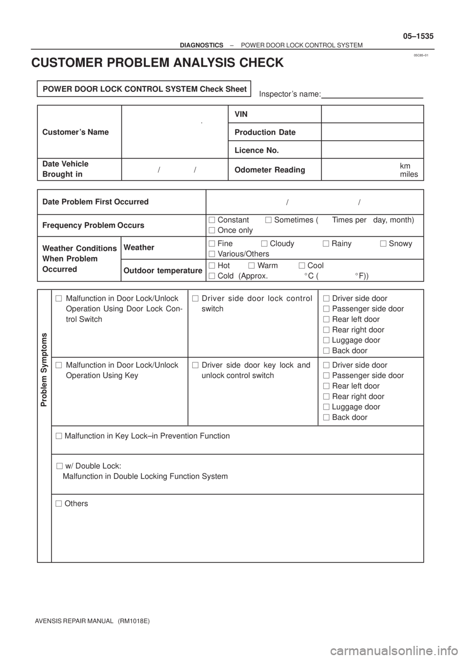
05C85±01
POWER DOOR LOCK CONTROL SYSTEM Check Sheet
Inspector 's name:
Customer 's Name
Date Vehicle
Brought inOdometer Reading / /
Weather Conditions
When Problem
Occurred Frequency Problem OccursWeather
Outdoor temperature
/ /
� Constant � Sometimes ( Times per day, month)
� Once only
Malfunction in Door Lock/Unlock
Operation Using Door Lock Con-
trol SwitchDriver side door lock control
switch
� Others
Date Problem First Occurred
� Fine � Cloudy � Rainy � Snowy
� Various/Others
� Hot � Warm � Cool
� Cold (Approx. �C ( �F))
Problem Symptoms
� Driver side door
� Passenger side door
� Rear left door
� Rear right door
� Luggage door
� Back door
Malfunction in Door Lock/Unlock
Operation Using KeyDriver side door key lock and
unlock control switch� Driver side door
� Passenger side door
� Rear left door
� Rear right door
� Luggage door
� Back door
� Malfunction in Key Lock±in Prevention Function �� �
�
km
miles
� w/ Double Lock:
Malfunction in Double Locking Function System
VIN
Production Date
Licence No.
± DIAGNOSTICSPOWER DOOR LOCK CONTROL SYSTEM
05±1535
AVENSIS REPAIR MANUAL (RM1018E)
CUSTOMER PROBLEM ANALYSIS CHECK
Page 1627 of 5135
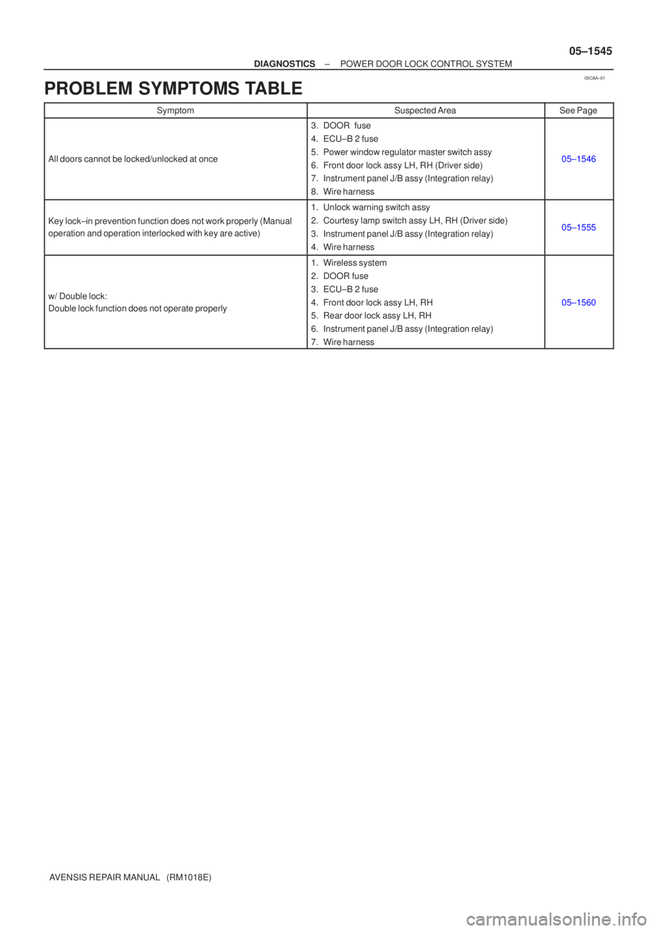
05C8A±01
±
DIAGNOSTICS POWER DOOR LOCK CONTROL SYSTEM
05±1545
AVENSIS REPAIR MANUAL (RM1018E)
PROBLEM SYMPTOMS TABLE
SymptomSuspected AreaSee Page
All doors cannot be locked/unlocked at once
3. DOOR fuse
4. ECU±B 2 fuse
5. Power window regulator master switch assy
6. Front door lock assy LH, RH (Driver side)
7. Instrument panel J/B assy (Integration relay)
8. Wire harness
05±1546
Key lock±in prevention function does not work properly (Manual
operation and operation interlocked with key are active)
1. Unlock warning switch assy
2. Courtesy lamp switch assy LH, RH (Driver side)
3. Instrument panel J/B assy (Integration relay)
4. Wire harness
05±1555
w/ Double lock:
Double lock function does not operate properly
1. Wireless system
2. DOOR fuse
3. ECU±B 2 fuse
4. Front door lock assy LH, RH
5. Rear door lock assy LH, RH
6. Instrument panel J/B assy (Integration relay)
7. Wire harness
05±1560
Page 1957 of 5135
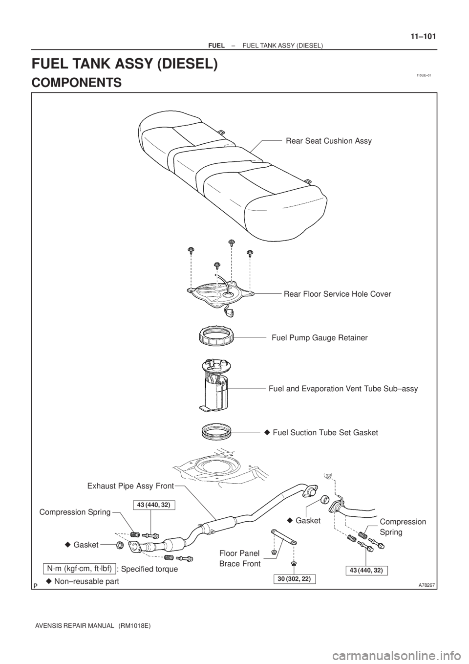
110UE±01
A78267
Rear Seat Cushion Assy
Rear Floor Service Hole Cover
Fuel Pump Gauge Retainer
Fuel and Evaporation Vent Tube Sub±assy
N´m (kgf´cm, ft´lbf)
: Specified torque
� Non±reusable part� Fuel Suction Tube Set Gasket
� Gasket� Gasket Exhaust Pipe Assy Front
Compression Spring
Floor Panel
Brace FrontCompression
Spring43 (440, 32)
30 (302, 22)
43 (440, 32)
± FUELFUEL TANK ASSY (DIESEL)
11±101
AVENSIS REPAIR MANUAL (RM1018E)
FUEL TANK ASSY (DIESEL)
COMPONENTS
Page 2401 of 5135
A57099
A56702
17±26
± LUBRICATIONOIL PUMP ASSY (1CD±FTV)
AVENSIS REPAIR MANUAL (RM1018E)
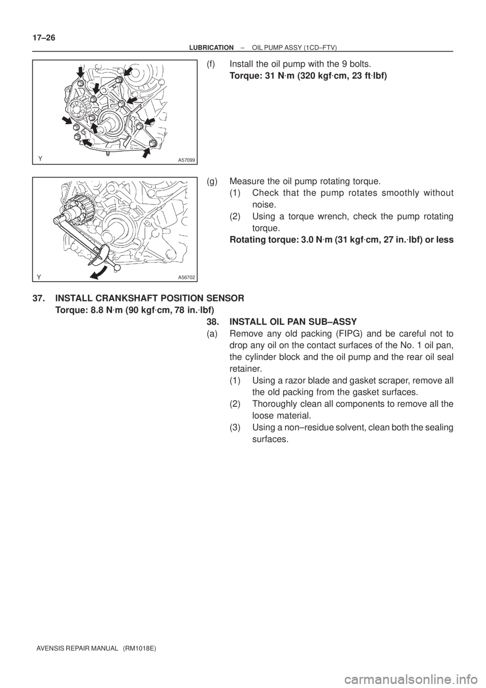
(f) Install the oil pump with the 9 bolts.
Torque: 31 N�m (320 kgf�cm, 23 ft�lbf)
(g) Measure the oil pump rotating torque.
(1) Check that the pump rotates smoothly without
noise.
(2) Using a torque wrench, check the pump rotating
torque.
Rotating torque: 3.0 N�m (31 kgf�cm, 27 in.�lbf) or less
37. INSTALL CRANKSHAFT POSITION SENSOR
Torque: 8.8 N�m (90 kgf�cm, 78 in.�lbf)
38. INSTALL OIL PAN SUB±ASSY
(a) Remove any old packing (FIPG) and be careful not to
drop any oil on the contact surfaces of the No. 1 oil pan,
the cylinder block and the oil pump and the rear oil seal
retainer.
(1) Using a razor blade and gasket scraper, remove all
the old packing from the gasket surfaces.
(2) Thoroughly clean all components to remove all the
loose material.
(3) Using a non±residue solvent, clean both the sealing
surfaces.
Page 2809 of 5135
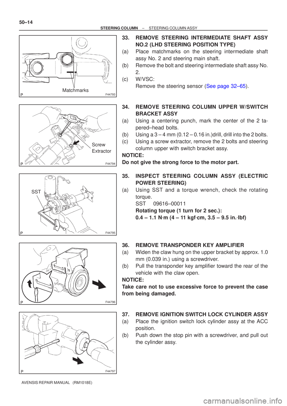
F44793Matchmarks
F44794
Screw
Extractor
F44795
SST
F44796
F44797
50±14
±
STEERING COLUMN STEERING COLUMN ASSY
AVENSIS REPAIR MANUAL (RM1018E)
33. REMOVE STEERING INTERMEDIATE SHAFT ASSY NO.2 (LHD STEERING POSITION TYPE)
(a) Place matchmarks on the steering intermediate shaft
assy No. 2 and steering main shaft.
(b) Remove the bolt and steering intermediate shaft assy No. 2.
(c) W/VSC:
Remove the steering sensor (See page 32±65).
34. REMOVE STEERING COLUMN UPPER W/SWITCH BRACKET ASSY
(a) Using a centering punch, mark the center of the 2 ta- pered±head bolts.
(b) Using a 3 ± 4 mm (0.12 ± 0.16 in.)drill, drill into the 2 bolts.
(c) Using a screw extractor, remove the 2 bolts and steering column upper with switch bracket assy.
NOTICE:
Do not give the strong force to the motor part.
35. INSPECT STEERING COLUMN ASSY (ELECTRIC POWER STEERING)
(a) Using SST and a torque wrench, check the rotating torque.
SST 09616±00011
Rotating torque (1 turn for 2 sec.):
0.4 ± 1.1 N �m (4 ± 11 kgf �cm, 3.5 ± 9.5 in. �lbf)
36. REMOVE TRANSPONDER KEY AMPLIFIER
(a) Widen the claw hung on the upper bracket by approx. 1.0 mm (0.039 in.) using a screwdriver.
(b) Pull the transponder key amplifier toward the rear of the
vehicle with the claw open.
NOTICE:
Take care not to use excessive force to prevent the case
from being damaged.
37. REMOVE IGNITION SWITCH LOCK CYLINDER ASSY
(a) Place the ignition switch lock cylinder assy at the ACC position.
(b) Push down the stop pin with a screwdriver, and pull out the cylinder assy.